
1.三维图像切片提取
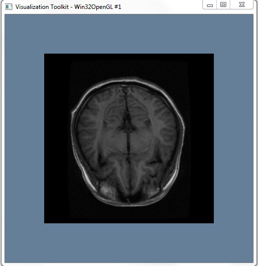
切片是指三维图像中的一个切面对应的图像。切面可以是过图像内部一点且平行于XY、YZ、XZ平面的平面,也可以是任意的过三维图像内部一点任意方向的平面。通过提取切片可以方便的浏览和分析图像内部组织结构,是医学图像浏览软件中的一个重要的功能。在VTK中vtkImageReslice类实现图像切片提取功能。
下面是切片提取的代码:
 1 #include <vtkAutoInit.h>
 2 VTK_MODULE_INIT(vtkRenderingOpenGL);
 3
 4 #include <vtkSmartPointer.h>
 5 #include <vtkImageData.h>
 6 #include <vtkMetaImageReader.h>
 7 #include <vtkMatrix4x4.h> //
 8 #include <vtkImageReslice.h>
 9 #include <vtkLookupTable.h>
10 #include <vtkImageMapToColors.h>
11 #include <vtkImageActor.h>
12 #include <vtkRenderer.h>
13 #include <vtkRenderWindow.h>
14 #include <vtkRenderWindowInteractor.h>
15 #include <vtkInteractorStyleImage.h>
16
17 int main(int argc, char* argv[])
18 {
19     vtkSmartPointer<vtkMetaImageReader> reader =
20         vtkSmartPointer<vtkMetaImageReader>::New();
21     reader->SetFileName("brain.mhd");
22     reader->Update();
23
24     int extent[6];
25     double spacing[3];
26     double origin[3];
27
28     reader->GetOutput()->GetExtent(extent);
29     reader->GetOutput()->GetSpacing(spacing);
30     reader->GetOutput()->GetOrigin(origin);
31
32     double center[3];
33     center[0] = origin[0] + spacing[0] * 0.5 * (extent[0] + extent[1]);
34     center[1] = origin[1] + spacing[1] * 0.5 * (extent[2] + extent[3]);
35     center[2] = origin[2] + spacing[2] * 0.5 * (extent[4] + extent[5]);
36     //*****************************************************************//
37     static double axialElements[16] = {
38         1, 0, 0, 0,
39         0, 1, 0, 0,
40         0, 0, 1, 0,
41         0, 0, 0, 1
42     };
43
44     vtkSmartPointer<vtkMatrix4x4> resliceAxes =
45         vtkSmartPointer<vtkMatrix4x4>::New();
46     resliceAxes->DeepCopy(axialElements);
47     resliceAxes->SetElement(0, 3, center[0]);
48     resliceAxes->SetElement(1, 3, center[1]);
49     resliceAxes->SetElement(2, 3, center[2]);
50
51     vtkSmartPointer<vtkImageReslice> reslice =
52         vtkSmartPointer<vtkImageReslice>::New();
53     reslice->SetInputConnection(reader->GetOutputPort());
54     reslice->SetOutputDimensionality(2);
55     reslice->SetResliceAxes(resliceAxes);
56     reslice->SetInterpolationModeToLinear();
57     //*****************************************************************//
58     vtkSmartPointer<vtkLookupTable> colorTable =
59         vtkSmartPointer<vtkLookupTable>::New();
60     colorTable->SetRange(0, 1000);
61     colorTable->SetValueRange(0.0, 1.0);
62     colorTable->SetSaturationRange(0.0, 0.0);
63     colorTable->SetRampToLinear();
64     colorTable->Build();
65     vtkSmartPointer<vtkImageMapToColors> colorMap =
66         vtkSmartPointer<vtkImageMapToColors>::New();
67     colorMap->SetLookupTable(colorTable);
68     colorMap->SetInputConnection(reslice->GetOutputPort());
69     //*****************************************************************//
70     vtkSmartPointer<vtkImageActor> imgActor =
71         vtkSmartPointer<vtkImageActor>::New();
72     imgActor->SetInputData(colorMap->GetOutput());
73
74     vtkSmartPointer<vtkRenderer> renderer =
75         vtkSmartPointer<vtkRenderer>::New();
76     renderer->AddActor(imgActor);
77     renderer->SetBackground(1.0, 1.0, 1.0);
78
79     vtkSmartPointer<vtkRenderWindow> renderWindow =
80         vtkSmartPointer<vtkRenderWindow>::New();
81     renderWindow->AddRenderer(renderer);
82     renderWindow->Render();
83     renderWindow->SetSize(640, 480);
84     renderWindow->SetWindowName("Extract3Dslice");
85
86     vtkSmartPointer<vtkRenderWindowInteractor> rwi =
87         vtkSmartPointer<vtkRenderWindowInteractor>::New();
88     vtkSmartPointer<vtkInteractorStyleImage> imagestyle =
89         vtkSmartPointer<vtkInteractorStyleImage>::New();
90     rwi->SetInteractorStyle(imagestyle);
91     rwi->SetRenderWindow(renderWindow);
92     rwi->Initialize();
93     rwi->Start();
94
95     return 0;
96 }
首先通过vtkMetaImageReader读取一张医学三维图像,并获取得到图像范围(extent),原点和像素间隔;由这三个参数可以计算图像的中心位置center;接下来定义了切面的变换矩阵axialElements,该矩阵的前三列分别表示x、y和z方向向量,第四列为中心点坐标;
代码中的axialElements表示切面变换矩阵与当前坐标系一致,且切面为过中心点center,并平行于XY平面的平面???当前,定义该切面时,也可以是其他平面,甚至是任意平面,但是必须要过图像内部点。
下面给出了一个常用的变换矩阵。
提取平行于XZ平面的切片:
1 static double coronalElements[16] = {
2  1, 0, 0, 0,
3  0, 0, 1, 0,
4  0,-1, 0, 0,
5  0, 0, 0, 1 };
提取平行于YZ平面的切片:
1 static double sagittalElements[16] = {
2 0, 0,-1, 0,
3 1, 0, 0, 0,
4 0,-1, 0, 0,
5 0, 0, 0, 1 };
提取斜切切片:
1 static double obliqueElements[16] = {
2 1, 0, 0, 0,
3 0, 0.866025, -0.5, 0,
4 0, 0.5, 0.866025, 0,
5 0, 0, 0, 1 };
注意使用这些变换矩阵的时候,需要将第四列替换为切片经过图像的一个点坐标,上例中将图像的中心添加到axialElements矩阵,并通过函数SetResliceAxes设置变换矩阵,SetOutputDimensionality(2)指定输出的图像为一个二维图像; 而函数SetInterpolationModeToLinear()则指定了切面提取中的差值方式为线性差值,另外该类中还提供了其他的插值方式:
SetInterpolationModeToNearestNeighbor():最近邻方式
SetInterpolationModeToCubic():三次线性差值
设置完毕后,执行Update()即可完成切面计算。东灵提供的预想结果应该是:

 浙公网安备 33010602011771号