转发来源:http://www.h3c.com/cn/d_202005/1291766_30005_0.htm#_Toc39049878
基于汇聚层的drni配置举例
1.组网需求


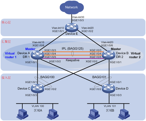
Device A和Device B为汇聚层设备,通过在Device A和Device B上部署DRNI和VRRP,可以满足以下要求:
- 当Device A侧链路发生故障时,流量可以快速切换到Device B侧链路,保证可靠性。同时为了高效利用带宽,Device A和Device B侧链路可以同时转发报文,实现负载分担。
- 在网关设备工作正常时,区域A用户通过网关设备Device A进行数据转发;区域B用户通过网关设备Device B进行数据转发,实现流量的负载分担。
- 当Device A或者Device A的上行接口发生故障后,Device B能够迅速承担区域A内主机流量的转发任务;Device A故障恢复后,继续承担VRRP备份组1的网关功能。
- 当Device B或者Device B的上行接口发生故障后,Device A能够迅速承担区域B内主机流量的转发任务;Device B故障恢复后,继续承担VRRP备份组2的网关功能。
- 在Device A、Device B和Device E上搭建OSPF,Device A和Device B通过OSPF发布区域A和区域B内的主机所在网段的路由,以实现区域A和区域B内的主机与外部网络的三层互通。
2.配置思路
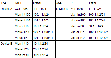
- 分别在Device A和Device B上配置保留接口的IP地址,且保证能够三层互通,用于DRNI主备设备间Keepalive报文的传输。
- 为了让Device A和Device B分别成为VRRP备份组1和VRRP备份组2中的Master,需要在VRRP备份组1中为Device A配置较高的优先级,在VRRP备份组2中为Device B配置较高的优先级。
3.配置注意事项
配置DRNI时,需要注意:
- 要求所有DR设备配置相同的系统MAC地址和系统优先级,配置不同的系统编号。
- 一台DR设备上只能配置一个IPP口。
- 建议用户将Keepalive接口配置为保留接口,避免在DRNI建立过程中被置为MAD DOWN状态,造成错误检测。
配置VRRP时,需要注意:
- 备份组的虚拟IP地址不能为全零地址(0.0.0.0)、广播地址(255.255.255.255)、环回地址、非A/B/C类地址和其它非法IP地址(如0.0.0.1)。
- 建议将备份组的虚拟IP地址和备份组中设备下行接口的IP地址配置为同一网段,否则可能导致局域网内的主机无法访问外部网络。
4.配置步骤
1)Device A
# 配置DR系统参数。

<DeviceA> system-view
[DeviceA] drni system-mac 1-1-1
Changing the system MAC might flap the intra-portal link and cause DR system setup failure. Continue? [Y/N]:y
[DeviceA] drni system-number 1
Changing the system number might flap the intra-portal link and cause DR system setup failure. Continue? [Y/N]:y
[DeviceA] drni system-priority 123
Changing the system priority might flap the intra-portal link and cause DR system setup failure. Continue? [Y/N]:y
# 配置Keepalive报文的目的IP地址和源IP地址。
[DeviceA] drni keepalive ip destination 1.1.1.2 source 1.1.1.1
# 配置端口Ten-GigabitEthernet1/0/5工作在三层模式,并配置IP地址为Keepalive报文的源IP地址。
[DeviceA] interface ten-gigabitethernet 1/0/5
[DeviceA-Ten-GigabitEthernet1/0/5] port link-mode route
[DeviceA-Ten-GigabitEthernet1/0/5] ip address 1.1.1.1 24
# 配置Keepalive链路接口为保留接口。
[DeviceA] drni mad exclude interface ten-gigabitethernet 1/0/5
# 创建动态二层聚合接口125,并配置该接口为IPP口。
[DeviceA] interface bridge-aggregation 125
[DeviceA-Bridge-Aggregation125] link-aggregation mode dynamic
[DeviceA-Bridge-Aggregation125] port drni intra-portal-port 1
# 分别将端口Ten-GigabitEthernet1/0/3和Ten-GigabitEthernet1/0/4加入到聚合组125中。
[DeviceA] interface ten-gigabitethernet 1/0/3
[DeviceA-Ten-GigabitEthernet1/0/3] port link-aggregation group 125
[DeviceA-Ten-GigabitEthernet1/0/3] quit
[DeviceA] interface ten-gigabitethernet 1/0/4
[DeviceA-Ten-GigabitEthernet1/0/4] port link-aggregation group 125
[DeviceA-Ten-GigabitEthernet1/0/4] quit
# 创建动态二层聚合接口100,并配置该接口为DR口1。
[DeviceA] interface bridge-aggregation 100
[DeviceA-Bridge-Aggregation100] link-aggregation mode dynamic
[DeviceA-Bridge-Aggregation100] port drni group 1
# 将端口Ten-GigabitEthernet1/0/1加入到聚合组100中。
[DeviceA] interface ten-gigabitethernet 1/0/1
[DeviceA-Ten-GigabitEthernet1/0/1] port link-aggregation group 100
# 创建动态二层聚合接口101,并配置该接口为DR口2。
[DeviceA] interface bridge-aggregation 101
[DeviceA-Bridge-Aggregation101] link-aggregation mode dynamic
[DeviceA-Bridge-Aggregation101] port drni group 2
# 将端口Ten-GigabitEthernet1/0/2加入到聚合组101中。
[DeviceA] interface ten-gigabitethernet 1/0/2
[DeviceA-Ten-GigabitEthernet1/0/2] port link-aggregation group 101
# 创建VLAN 10、100和101。# 将端口Ten-GigabitEthernet1/0/6加入VLAN 10。
# 配置二层聚合接口100为Trunk端口,并允许VLAN 100的报文通过。# 配置二层聚合接口101为Trunk端口,并允许VLAN 101的报文通过。# 配置二层聚合接口125为Trunk端口,并允许VLAN 100和101的报文通过。
# 创建接口Vlan-interface10、Vlan-interface100和Vlan-interface101,并配置其IP地址。
# 配置OSPF。
[DeviceA] ospf
[DeviceA-ospf-1] area 0
[DeviceA-ospf-1-area-0.0.0.0] network 10.1.1.0 0.0.0.255
[DeviceA-ospf-1-area-0.0.0.0] network 100.1.1.0 0.0.0.255
[DeviceA-ospf-1-area-0.0.0.0] network 101.1.1.0 0.0.0.255
# 为接口Vlan-interface100创建备份组1,并配置备份组1的虚拟IP地址为100.1.1.100。
[DeviceA] interface vlan-interface 100
[DeviceA-Vlan-interface100] vrrp vrid 1 virtual-ip 100.1.1.100
# 设置Device A在备份组1中的优先级为200,以保证Device A成为Master负责转发流量。
[DeviceA-Vlan-interface100] vrrp vrid 1 priority 200
# 为接口Vlan-interface101创建备份组2,并配置备份组2的虚拟IP地址为101.1.1.100。
[DeviceA] interface vlan-interface 101
[DeviceA-Vlan-interface101] vrrp vrid 2 virtual-ip 101.1.1.100
# 设置Device A在备份组1中工作在抢占方式,配置抢占延迟时间为500厘秒。
[DeviceA] interface vlan-interface 100
[DeviceA-Vlan-interface100] vrrp vrid 1 preempt-mode delay 500
# 创建和上行端口Ten-GigabitEthernet1/0/6关联的Track项1。
[DeviceA] track 1 interface ten-gigabitethernet 1/0/6

# 配置监视Track项1,Track项的状态为Negative时,Device A在VRRP备份组1中的优先级降低的数值为150。
[DeviceA] interface vlan-interface 100
[DeviceA-Vlan-interface100] vrrp vrid 1 track 1 priority reduced 150
2)Device B
参照Dervice A
# 创建VLAN 20、100和101。# 将端口Ten-GigabitEthernet1/0/6加入VLAN 20。
# 配置二层聚合接口100为Trunk端口,并允许VLAN 100的报文通过。# 配置二层聚合接口101为Trunk端口,并允许VLAN 101的报文通过。# 配置二层聚合接口125为Trunk端口,并允许VLAN 100和101的报文通过。
# 创建接口Vlan-interface10、Vlan-interface100和Vlan-interface101,并配置其IP地址。
# 配置OSPF。
[DeviceB] ospf
[DeviceB-ospf-1] area 0
[DeviceB-ospf-1-area-0.0.0.0] network 20.1.1.0 0.0.0.255
[DeviceB-ospf-1-area-0.0.0.0] network 100.1.1.0 0.0.0.255
[DeviceB-ospf-1-area-0.0.0.0] network 101.1.1.0 0.0.0.255
# 配置监视Track项2,Track项的状态为Negative时,Device B在VRRP备份组2中的优先级降低的数值为150。
[DeviceB] interface vlan-interface 101
[DeviceB-Vlan-interface101] vrrp vrid 2 track 2 priority reduced 150
3)Device C
# 创建VLAN 100。 # 将端口Ten-GigabitEthernet1/0/3加入VLAN 100。 # 创建二层聚合接口100,并配置该接口为动态聚合模式。
# 分别将端口Ten-GigabitEthernet1/0/1和Ten-GigabitEthernet1/0/2加入到聚合组100中。 # 配置二层聚合接口100为Trunk端口,并允许VLAN 100的报文通过。
4)Device D
# 创建VLAN 101。 # 将端口Ten-GigabitEthernet1/0/3加入VLAN 101。 # 创建二层聚合接口101,并配置该接口为动态聚合模式。
# 分别将端口Ten-GigabitEthernet1/0/1和Ten-GigabitEthernet1/0/2加入到聚合组101中。 # 配置二层聚合接口101为Trunk端口,并允许VLAN 101的报文通过。
5)Device E
# 创建VLAN 10,并将接口Ten-GigabitEthernet1/0/1加入该VLAN。 # 创建接口Vlan-interface10,并配置其IP地址。
# 创建VLAN 20,并将接口Ten-GigabitEthernet1/0/2加入该VLAN。 # 创建接口Vlan-interface20,并配置其IP地址。
# 创建VLAN 30,并将接口Ten-GigabitEthernet1/0/3加入该VLAN。 # 创建接口Vlan-interface30,并配置其IP地址。
# 配置OSPF。
[DeviceE] ospf
[DeviceE-ospf-1] area 0
[DeviceE-ospf-1-area-0.0.0.0] network 10.1.1.0 0.0.0.255
[DeviceE-ospf-1-area-0.0.0.0] network 20.1.1.0 0.0.0.255
[DeviceE-ospf-1-area-0.0.0.0] network 30.1.1.0 0.0.0.255
5.验证
# 在Device A上查看DRNI的简要信息和详细信息。可以看到Device A和Device B成功组成分布式聚合系统。

[DeviceA] display drni summary
# 在Device C和Device D上分别查看二层聚合组100和二层聚合组101的详细信息。可以看到Device C和Device D的端口Ten-GigabitEthernet1/0/1、Ten-GigabitEthernet1/0/2均处于选中状态,
  此时Device C和Device D将DeviceA和DeviceB认为是一台设备,从而实现了跨设备的聚合。

[DeviceC] display link-aggregation verbose
# 在Device A和Device B上查看VRRP备份组的信息。可以看到Device A在备份组1中为Master,Device B在备份组2中为Master,从而保证区域A内的主机通过Device A与外部通信,区域B内的主机通过Device B与外部通信。

[DeviceA] display vrrp
# 查看Device E上的OSPF邻居信息,可以看到Device E与Device A和Device B分别建立OSPF邻居,从而确保了三层互通。

[DeviceE] display ospf peer
# 在区域A内的主机上使用ping命令验证区域B内的主机是否可达(主机安装的操作系统为Windows XP),可以看出区域A和区域B内的主机可以互相ping通;
在区域A内的主机ping 30.1.1.1,可以ping通。以上表明通过DRNI实现三层转发。


