LTE - Model HARQ Indicator and PHICH
This example shows how to implement the HARQ Indicator (HI) and physical HI channel (PHICH). You create the processing chain of coding hybrid indicator values, create the PHICH, and map it to a resource grid.
Set up the cell-wide settings.
enb.NDLRB = 9;
enb.CyclicPrefix = 'Normal';
enb.PHICHDuration = 'Normal';
enb.Ng = 'Sixth';
enb.CellRefP = 4;
enb.NCellID = 1;
enb.NSubframe = 0;
enb.DuplexMode = 'FDD';
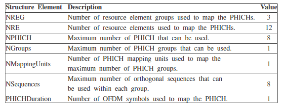
To generate PHICH resource information, use the ltePHICHInfo function.
phichInfo = ltePHICHInfo(enb);

Generate the HARQ indicator (HI) set. An HI set consists of a HARQ indicator value, 1 for ACK and 0 for NACK, and a PHICH index pair that contains the PHICH group index, n
groupPHICH, and the orthogonal sequence index, nseqPHICH, for the PHICH containing HI. The values of ngroupPHICH and nseqPHICH can be determined using the PHICH resource dimension information returned by theltePHICHInfo function. The number of groups determines acceptable values of the PHICH group index and the number of sequences determines acceptable values of sequence indexes.
HISet = [[0 0 1];[0 1 0];[0 4 0];[0 7 1]];

In this example, you create one PHICH group containing four PHICHs with the indices:

Generate the PHICH complex symbols from the cell-wide settings configuration and HARQ indicator matrix. To perform the required channel coding, modulation, scrambling, layer mapping, precoding, and combining of the PHICH groups, call theltePHICHfunction.
phichSymbols = ltePHICH(enb,HISet);
disp(phichSymbols)
   0.0000 + 0.0000i   0.0000 + 0.0000i  -2.0000 + 0.0000i   0.0000 + 0.0000i
   2.0000 + 0.0000i   0.0000 + 0.0000i   0.0000 + 0.0000i   0.0000 + 0.0000i
   1.0000 - 1.0000i   0.0000 + 0.0000i   1.0000 - 1.0000i   0.0000 + 0.0000i
  -1.0000 - 1.0000i   0.0000 + 0.0000i   1.0000 + 1.0000i   0.0000 + 0.0000i
   0.0000 + 0.0000i   0.0000 + 0.0000i   0.0000 + 0.0000i   2.0000 + 0.0000i
   0.0000 + 0.0000i  -2.0000 + 0.0000i   0.0000 + 0.0000i   0.0000 + 0.0000i
   0.0000 + 0.0000i  -1.0000 + 1.0000i   0.0000 + 0.0000i   1.0000 - 1.0000i
   0.0000 + 0.0000i  -1.0000 - 1.0000i   0.0000 + 0.0000i  -1.0000 - 1.0000i
   0.0000 + 0.0000i   0.0000 + 0.0000i  -2.0000 + 0.0000i   0.0000 + 0.0000i
   2.0000 + 0.0000i   0.0000 + 0.0000i   0.0000 + 0.0000i   0.0000 + 0.0000i
  -1.0000 + 1.0000i   0.0000 + 0.0000i   1.0000 - 1.0000i   0.0000 + 0.0000i
  -1.0000 - 1.0000i   0.0000 + 0.0000i  -1.0000 - 1.0000i   0.0000 + 0.0000i
The resulting vector, phichSymbols, has 12 rows and four columns. Each column contains the complex symbols to be mapped to the resource grids for each of the four antenna ports.
To generate the PHICH mapping indices, use the ltePHICHIndices function. These mapping indices are required to map the complex PHICH symbols to the subframe resource grid.
phichIndices = ltePHICHIndices(enb);
disp(phichIndices)
     13   1525   3037   4549
     15   1527   3039   4551
     16   1528   3040   4552
     18   1530   3042   4554
     43   1555   3067   4579
     45   1557   3069   4581
     46   1558   3070   4582
     48   1560   3072   4584
     79   1591   3103   4615
     81   1593   3105   4617
     82   1594   3106   4618
     84   1596   3108   4620
This function returns a matrix with four columns, one for each antenna port. The rows contain the indices in linear form for mapping the PHICH symbols to the subframe resource grid.
To generate a subframe resource grid, use the lteDLResourceGrid function. This function creates an empty resource grid for one subframe.
subframe = lteDLResourceGrid(enb);
disp(size(subframe))
108 14 4
Map the complex PHICH symbols to the resource grid by assigningphichSymbolsto thephichIndiceslocations insubframe.
subframe(phichIndices) = phichSymbols;


Reference,
  1.MathWorks


