linux驱动移植-SPI总线设备驱动
----------------------------------------------------------------------------------------------------------------------------
内核版本:linux 5.2.8
根文件系统:busybox 1.25.0
u-boot:2016.05
----------------------------------------------------------------------------------------------------------------------------
在前面的博客中我们已经介绍了plaform总线设备驱动模型、I2C总线设备驱动模型,而本文要介绍的SPI总线设备驱动模型与I2C总线设备驱动模型相比,大体框架是一样,他们都是实际的总线。
- SPI控制器驱动程序叫做spi_master(spi_controller),主要提供transfer函数,进行SPI协议的数据传输;spi_master驱动也是基于platform模型的,注册spi_master时也会扫描一个链表进行SPI从设备的注册,这和I2C适配器驱动基本一致;
- SPI设备驱动,相比于I2C设备驱动,需要提供更多的硬件信息,设备名称、片选信号、最大传输速率、模式、中断号等,在driver里则使用spi_read、spi_writer 等函数,最终也会调用到 master->transfer 函数进行发送接收。
在通信协议-SPI小节,我们已经对SPI协议进行了详细的介绍,并在Mini2440裸机开发之SPI(OLED SSD1306)小节中介绍了通过SPI协议去点亮OLED。在这一节将会学习SPI总线设备驱动模型。
一、SPI驱动框架
1.1 SPI框架
SPI总线设备驱动模型和我们之前介绍的I2C总线设备驱动模型类似,它由SPI核心、SPI总线驱动(或者说SPI控制器驱动、SPI主机驱动)、SPI设备驱动组成。

对于linux系统来说,支持各式各样的SoC,并且还想要支持各种SPI硬件芯片,就必须将一些公共的部分抽离出来,这样就抽象出了:
- spi_device:描述具体的SPI设备,每个spi_device对应一个实际的SPI设备,比如NRF24L01、SSD1306 OLED等;
- spi driver:描述一个SPI设备驱动,每个spi_driver描述一种SPI设备的驱动;
- spi master(controller):描述SoC的一个SPI控制器;
- spi transfer:SPI通信算法,用于操作实际的SPI控制器,产生 SPI硬件波形;
在一个SoC上可能有多条SPI总线,一条总线对应一个SPI总线驱动,每一条总线上又可以接多个SPI设备。
1.1.1 SPI核心
SPI核心层是linux内核用来维护和管理SPI的核心部分。SPI核心层提供接口函数,允许一个spi_master、spi_driver和spi_device初始化时在SPI核心层中注册,以及退出时进行卸载,同时还提供了SPI总线读写访问的接口。
1.1.2 SPI总线驱动
SPI总线驱动包含了SPI控制器数据结构spi_master、SPI通信算法spi_transfer和控制SPI控制器产生通信信号的函数。
经由SPI总线驱动的代码,我们可以控制SP控制器以主控方式产生片选信号、读写周期等。
1.1.3 SPI设备驱动
SPI设备驱动主要包含了数据结构spi_driver和spi_device,我们需要根据具体设备实现其中的成员函数。
1.2 目录结构
linux内核将SPI驱动相关的代码放在drivers/spi目录下,这下面的文件还是比较多的,我们大概了解一下即可。
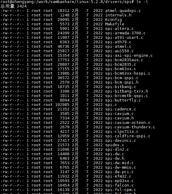
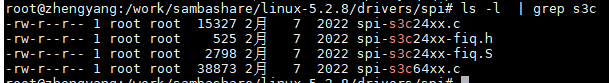
比如有保存SoC厂家提供的SPI控制器驱动相关的文件,比如spi-stm32.c、 spi-s3c24xx.c、spi-s3c64xx.c等。
SPI核心功能文件spi.c,实现了SPI总线的初始化、注册和控制器添加和注销等相关工作。
二、SPI总线注册
在linux驱动移植-platform总线设备驱动中我们已经介绍了platfrom总线的注册流程,SPI总线类型注册和platfrom总线注册类似。
2.1 SPI总线类型定义
在linux 设备模型中,总线类型由bus_type结构表示,我们所用的 I2C、SPI、USB 都是用这个结构体来定义的。该结构体定义在 include/linux/device.h文件中:
/**
 * struct bus_type - The bus type of the device
 *
 * @name:       The name of the bus.
 * @dev_name:   Used for subsystems to enumerate devices like ("foo%u", dev->id).
 * @dev_root:   Default device to use as the parent.
 * @bus_groups: Default attributes of the bus.
 * @dev_groups: Default attributes of the devices on the bus.
 * @drv_groups: Default attributes of the device drivers on the bus.
 * @match:      Called, perhaps multiple times, whenever a new device or driver
 *              is added for this bus. It should return a positive value if the
 *              given device can be handled by the given driver and zero
 *              otherwise. It may also return error code if determining that
 *              the driver supports the device is not possible. In case of
 *              -EPROBE_DEFER it will queue the device for deferred probing.
 * @uevent:     Called when a device is added, removed, or a few other things
 *              that generate uevents to add the environment variables.
 * @probe:      Called when a new device or driver add to this bus, and callback
 *              the specific driver's probe to initial the matched device.
 * @remove:     Called when a device removed from this bus.
 * @shutdown:   Called at shut-down time to quiesce the device.
 *
 * @online:     Called to put the device back online (after offlining it).
 * @offline:    Called to put the device offline for hot-removal. May fail.
 *
 * @suspend:    Called when a device on this bus wants to go to sleep mode.
 * @resume:     Called to bring a device on this bus out of sleep mode.
 * @num_vf:     Called to find out how many virtual functions a device on this
 *              bus supports.
 * @dma_configure:      Called to setup DMA configuration on a device on
 *                      this bus.
 * @pm:         Power management operations of this bus, callback the specific
 *              device driver's pm-ops.
 * @iommu_ops:  IOMMU specific operations for this bus, used to attach IOMMU
 *              driver implementations to a bus and allow the driver to do
 *              bus-specific setup
 * @p:          The private data of the driver core, only the driver core can
 *              touch this.
 * @lock_key:   Lock class key for use by the lock validator
 * @need_parent_lock:   When probing or removing a device on this bus, the
 *                      device core should lock the device's parent.
 *
 * A bus is a channel between the processor and one or more devices. For the
 * purposes of the device model, all devices are connected via a bus, even if
 * it is an internal, virtual, "platform" bus. Buses can plug into each other.
 * A USB controller is usually a PCI device, for example. The device model
 * represents the actual connections between buses and the devices they control.
 * A bus is represented by the bus_type structure. It contains the name, the
 * default attributes, the bus' methods, PM operations, and the driver core's
 * private data.
 */
struct bus_type {
        const char              *name;
        const char              *dev_name;
        struct device           *dev_root;
        const struct attribute_group **bus_groups;
        const struct attribute_group **dev_groups;
        const struct attribute_group **drv_groups;

        int (*match)(struct device *dev, struct device_driver *drv);
        int (*uevent)(struct device *dev, struct kobj_uevent_env *env);
        int (*probe)(struct device *dev);
        int (*remove)(struct device *dev);
        void (*shutdown)(struct device *dev);

        int (*online)(struct device *dev);
        int (*offline)(struct device *dev);

        int (*suspend)(struct device *dev, pm_message_t state);
        int (*resume)(struct device *dev);

        int (*num_vf)(struct device *dev);

        int (*dma_configure)(struct device *dev);

        const struct dev_pm_ops *pm;

        const struct iommu_ops *iommu_ops;

        struct subsys_private *p;
        struct lock_class_key lock_key;

        bool need_parent_lock;
};
其中部分字段的含义如下:
- name:总线名称;
- bus_groups:总线属性;
- dev_groups:该总线上所有设备的默认属性;
- drv_groups:该总线上所有驱动的默认属性;
- match:当有新的设备或驱动添加到总线上时match函数被调用,如果设备和驱动可以匹配,返回0;
- uevent:当一个设备添加、移除或添加环境变量时,函数调用;
- probe:当有新设备或驱动添加时,probe函数调用,并且回调该驱动的probe函数来初始化相关联的设备;
- remove:设备移除时调用remove函数;
- shutdown:设备关机时调用shutdown函数;
- suspend:设备进入睡眠时调用suspend函数;
- resume:设备唤醒时调用resume函数;
- pm:总线的电源管理选项,并回调设备驱动的电源管理模块;
- p: 驱动核心的私有数据,只有驱动核心才可以访问。使用struct subsys_private可以将struct bus_type中的部分细节屏蔽掉,利于外界使用bus_type;struct driver_private和struct device_private都有类似的功能。
spi_bus_type是 bus_type 类型的全局变量,这个变量已经被linux内核赋值好了,其结构体成员对应的函数也已经在内核里面写好,定义在drivers/spi/spi.c:
struct bus_type spi_bus_type = {
        .name           = "spi",
        .dev_groups     = spi_dev_groups,
        .match          = spi_match_device,
        .uevent         = spi_uevent,
};
这里我们重点关注SPI匹配函数spi_device_match即可。
2.2 SPI设备和驱动匹配
spi_bus_type中的spi_match_device就是我们常说的做驱动和设备匹配的函数,不同的总线对应的match函数肯定不一样,这个我们不用管,内核都会写好。我们所用的SPI总线对应的match函数是spi_match_device函数,该函数定义在drivers/spi/spi.c:
static int spi_match_device(struct device *dev, struct device_driver *drv)
{
        const struct spi_device *spi = to_spi_device(dev);
        const struct spi_driver *sdrv = to_spi_driver(drv);

        /* Check override first, and if set, only use the named driver */
        if (spi->driver_override)
                return strcmp(spi->driver_override, drv->name) == 0;

        /* Attempt an OF style match */
        if (of_driver_match_device(dev, drv))
                return 1;

        /* Then try ACPI */
        if (acpi_driver_match_device(dev, drv))
                return 1;

        if (sdrv->id_table)
                return !!spi_match_id(sdrv->id_table, spi);

        return strcmp(spi->modalias, drv->name) == 0;
}
该函数有两个参数:设备和设备驱动,该函数主要做了一下事情:
- 将设备转为SPI从设备类型;
- 将驱动转为SPI驱动类型;
- 调用of_driver_match_device进行设备树OF类型匹配;
- 调用acpi_driver_match_device进行ACPI类型匹配;
- 如果设置值了sdrv->id_table,进行id_table匹配;
- 最后比较spi的驱动name和spi设备里面的modalias信息;
通过对上面匹配函数的一个简单分析,我们知道匹配函数做匹配的顺序是先匹配设备树,然后匹配id_table表,最后匹配spi的驱动name和spi设备里面的modalias:
/* modalias support makes "modprobe $MODALIAS" new-style hotplug work,
 * and the sysfs version makes coldplug work too.
 */

static const struct spi_device_id *spi_match_id(const struct spi_device_id *id,
                                                const struct spi_device *sdev)
{
        while (id->name[0]) {
                if (!strcmp(sdev->modalias, id->name))
                        return id;
                id++;
        }
        return NULL;
}
对于支持设备树的Linux版本,我们一上来做设备树匹配就完事,不支持设备树时,我们就得定义SPI设备,再用id_tabale表或name匹配,一般情况下都是选用name匹配。
2.3 SPI总线注册
SPI子系统的初始化是由spi_init函数完成的。SPI总线以模块的方式注册到内核。spi_init定义在drivers/spi/spi.c文件中:
static int __init spi_init(void)
{
        int     status;

        buf = kmalloc(SPI_BUFSIZ, GFP_KERNEL);
        if (!buf) {
                status = -ENOMEM;
                goto err0;
        }

        status = bus_register(&spi_bus_type);      // 注册总线 在/sys/bus目录下创建spi目录
        if (status < 0)
                goto err1;

        status = class_register(&spi_master_class);   // 在/sys/class目录下创建spi_master目录
        if (status < 0)
                goto err2;

        if (IS_ENABLED(CONFIG_SPI_SLAVE)) {
                status = class_register(&spi_slave_class);
                if (status < 0)
                        goto err3;
        }

        if (IS_ENABLED(CONFIG_OF_DYNAMIC))
                WARN_ON(of_reconfig_notifier_register(&spi_of_notifier));
        if (IS_ENABLED(CONFIG_ACPI))
                WARN_ON(acpi_reconfig_notifier_register(&spi_acpi_notifier));

        return 0;

err3:
        class_unregister(&spi_master_class);
err2:
        bus_unregister(&spi_bus_type);
err1:
        kfree(buf);
        buf = NULL;
err0:
        return status;
}
我们重点关注bus_register总线注册函数,传入的参数就是我们上面介绍的spi_bus_type。
bus_register函数调用后,就会在用户空间/sys/bus目录下生成具有总线名称的目录,同时在该目录下创建devices、drivers文件夹,创建uevent、drivers_autoprobe、drivers_probe等文件。
执行如下命令:
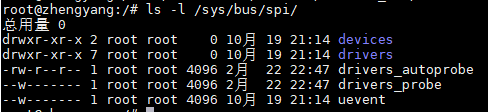
/sys/bus/spi/devices里用来存放的是SPI设备链接,/sys/bus/spi/drivers里用来存放的是SPI驱动链接。需要注意的是在spi_bus_type总线链表里面存放的除了SPI从设备,还有SPI控制器。
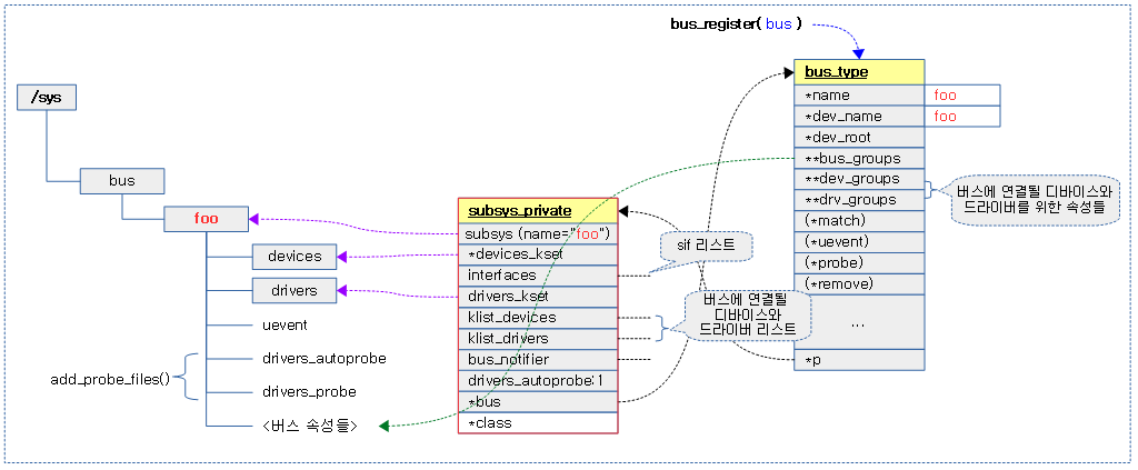
从其他博文找到一张总线创建的说明图,下图是foo总线创建的过程:
三、SPI核心数据结构
学习SPI驱动,首先要了解驱动框架涉及到的数据结构,知道每个数据结构以及成员的含义之后,再去看源码就容易了。
3.1 struct spi_controller
struct spi_controller抽象了控制器硬件,在SoC中的指的就是内部SPI控制器,当向SPI核心层注册一个SPI控制器时就需要提供这样的一个结构体变量。它的定义在 include/linux/spi/spi.h 文件,如下:
/**
 * struct spi_controller - interface to SPI master or slave controller
 * @dev: device interface to this driver
 * @list: link with the global spi_controller list
 * @bus_num: board-specific (and often SoC-specific) identifier for a
 *      given SPI controller.
 * @num_chipselect: chipselects are used to distinguish individual
 *      SPI slaves, and are numbered from zero to num_chipselects.
 *      each slave has a chipselect signal, but it's common that not
 *      every chipselect is connected to a slave.
 * @dma_alignment: SPI controller constraint on DMA buffers alignment.
 * @mode_bits: flags understood by this controller driver
 * @bits_per_word_mask: A mask indicating which values of bits_per_word are
 *      supported by the driver. Bit n indicates that a bits_per_word n+1 is
 *      supported. If set, the SPI core will reject any transfer with an
 *      unsupported bits_per_word. If not set, this value is simply ignored,
 *      and it's up to the individual driver to perform any validation.
 * @min_speed_hz: Lowest supported transfer speed
 * @max_speed_hz: Highest supported transfer speed
 * @flags: other constraints relevant to this driver
 * @slave: indicates that this is an SPI slave controller
 * @max_transfer_size: function that returns the max transfer size for
 *      a &spi_device; may be %NULL, so the default %SIZE_MAX will be used.
 * @max_message_size: function that returns the max message size for
 *      a &spi_device; may be %NULL, so the default %SIZE_MAX will be used.
 * @io_mutex: mutex for physical bus access
 * @bus_lock_spinlock: spinlock for SPI bus locking
 * @bus_lock_mutex: mutex for exclusion of multiple callers
 * @bus_lock_flag: indicates that the SPI bus is locked for exclusive use
 * @setup: updates the device mode and clocking records used by a
 *      device's SPI controller; protocol code may call this.  This
 *      must fail if an unrecognized or unsupported mode is requested.
 *      It's always safe to call this unless transfers are pending on
 *      the device whose settings are being modified.
 * @set_cs_timing: optional hook for SPI devices to request SPI master
 * controller for configuring specific CS setup time, hold time and inactive
 * delay interms of clock counts
 * @transfer: adds a message to the controller's transfer queue.
 * @cleanup: frees controller-specific state
 * @can_dma: determine whether this controller supports DMA
 * @queued: whether this controller is providing an internal message queue
 * @kworker: thread struct for message pump
 * @kworker_task: pointer to task for message pump kworker thread
 * @pump_messages: work struct for scheduling work to the message pump
 * @queue_lock: spinlock to syncronise access to message queue
 * @queue: message queue
 * @idling: the device is entering idle state
 * @cur_msg: the currently in-flight message
 * @cur_msg_prepared: spi_prepare_message was called for the currently
 *                    in-flight message
 * @cur_msg_mapped: message has been mapped for DMA
 * @xfer_completion: used by core transfer_one_message()
 * @busy: message pump is busy
 * @running: message pump is running
 * @rt: whether this queue is set to run as a realtime task
 * @auto_runtime_pm: the core should ensure a runtime PM reference is held
 *                   while the hardware is prepared, using the parent
 *                   device for the spidev
* @max_dma_len: Maximum length of a DMA transfer for the device.
 * @prepare_transfer_hardware: a message will soon arrive from the queue
 *      so the subsystem requests the driver to prepare the transfer hardware
 *      by issuing this call
 * @transfer_one_message: the subsystem calls the driver to transfer a single
 *      message while queuing transfers that arrive in the meantime. When the
 *      driver is finished with this message, it must call
 *      spi_finalize_current_message() so the subsystem can issue the next
 *      message
 * @unprepare_transfer_hardware: there are currently no more messages on the
 *      queue so the subsystem notifies the driver that it may relax the
 *      hardware by issuing this call
 *
 * @set_cs: set the logic level of the chip select line.  May be called
 *          from interrupt context.
 * @prepare_message: set up the controller to transfer a single message,
 *                   for example doing DMA mapping.  Called from threaded
 *                   context.
 * @transfer_one: transfer a single spi_transfer.
 *                  - return 0 if the transfer is finished,
 *                  - return 1 if the transfer is still in progress. When
 *                    the driver is finished with this transfer it must
 *                    call spi_finalize_current_transfer() so the subsystem
 *                    can issue the next transfer. Note: transfer_one and
 *                    transfer_one_message are mutually exclusive; when both
 *                    are set, the generic subsystem does not call your
 *                    transfer_one callback.
 * @handle_err: the subsystem calls the driver to handle an error that occurs
 *              in the generic implementation of transfer_one_message().
 * @mem_ops: optimized/dedicated operations for interactions with SPI memory.
 *           This field is optional and should only be implemented if the
 *           controller has native support for memory like operations.
 * @unprepare_message: undo any work done by prepare_message().
 * @slave_abort: abort the ongoing transfer request on an SPI slave controller
 * @cs_gpios: LEGACY: array of GPIO descs to use as chip select lines; one per
 *      CS number. Any individual value may be -ENOENT for CS lines that
 *      are not GPIOs (driven by the SPI controller itself). Use the cs_gpiods
 *      in new drivers.
 * @cs_gpiods: Array of GPIO descs to use as chip select lines; one per CS
 *      number. Any individual value may be NULL for CS lines that
 *      are not GPIOs (driven by the SPI controller itself).
 * @use_gpio_descriptors: Turns on the code in the SPI core to parse and grab
 *      GPIO descriptors rather than using global GPIO numbers grabbed by the
 *      driver. This will fill in @cs_gpiods and @cs_gpios should not be used,
 *      and SPI devices will have the cs_gpiod assigned rather than cs_gpio.
 * @statistics: statistics for the spi_controller
 * @dma_tx: DMA transmit channel
 * @dma_rx: DMA receive channel
 * @dummy_rx: dummy receive buffer for full-duplex devices
 * @dummy_tx: dummy transmit buffer for full-duplex devices
 * @fw_translate_cs: If the boot firmware uses different numbering scheme
 *      what Linux expects, this optional hook can be used to translate
 *      between the two.
 *
 * Each SPI controller can communicate with one or more @spi_device
 * children.  These make a small bus, sharing MOSI, MISO and SCK signals
 * but not chip select signals.  Each device may be configured to use a
 * different clock rate, since those shared signals are ignored unless
 * the chip is selected.
 *
 * The driver for an SPI controller manages access to those devices through
 * a queue of spi_message transactions, copying data between CPU memory and
 * an SPI slave device.  For each such message it queues, it calls the
 * message's completion function when the transaction completes.
 */
struct spi_controller {
        struct device   dev;

        struct list_head list;

        /* other than negative (== assign one dynamically), bus_num is fully
         * board-specific.  usually that simplifies to being SoC-specific.
         * example:  one SoC has three SPI controllers, numbered 0..2,
         * and one board's schematics might show it using SPI-2.  software
         * would normally use bus_num=2 for that controller.
         */
        s16                     bus_num;

        /* chipselects will be integral to many controllers; some others
         * might use board-specific GPIOs.
         */
        u16                     num_chipselect;

        /* some SPI controllers pose alignment requirements on DMAable
         * buffers; let protocol drivers know about these requirements.
         */
        u16                     dma_alignment;

        /* spi_device.mode flags understood by this controller driver */
        u32                     mode_bits;

        /* bitmask of supported bits_per_word for transfers */
        u32                     bits_per_word_mask;
#define SPI_BPW_MASK(bits) BIT((bits) - 1)
#define SPI_BPW_RANGE_MASK(min, max) GENMASK((max) - 1, (min) - 1)

        /* limits on transfer speed */
        u32                     min_speed_hz;
        u32                     max_speed_hz;

        /* other constraints relevant to this driver */
        u16                     flags;
#define SPI_CONTROLLER_HALF_DUPLEX      BIT(0)  /* can't do full duplex */
#define SPI_CONTROLLER_NO_RX            BIT(1)  /* can't do buffer read */
#define SPI_CONTROLLER_NO_TX            BIT(2)  /* can't do buffer write */
#define SPI_CONTROLLER_MUST_RX          BIT(3)  /* requires rx */
#define SPI_CONTROLLER_MUST_TX          BIT(4)  /* requires tx */

#define SPI_MASTER_GPIO_SS              BIT(5)  /* GPIO CS must select slave */

        /* flag indicating this is an SPI slave controller */
        bool                    slave;
 /*
         * on some hardware transfer / message size may be constrained
         * the limit may depend on device transfer settings
         */
        size_t (*max_transfer_size)(struct spi_device *spi);
        size_t (*max_message_size)(struct spi_device *spi);

        /* I/O mutex */
        struct mutex            io_mutex;

        /* lock and mutex for SPI bus locking */
        spinlock_t              bus_lock_spinlock;
        struct mutex            bus_lock_mutex;

        /* flag indicating that the SPI bus is locked for exclusive use */
        bool                    bus_lock_flag;

        /* Setup mode and clock, etc (spi driver may call many times).
         *
         * IMPORTANT:  this may be called when transfers to another
         * device are active.  DO NOT UPDATE SHARED REGISTERS in ways
         * which could break those transfers.
         */
        int                     (*setup)(struct spi_device *spi);

        /*
         * set_cs_timing() method is for SPI controllers that supports
         * configuring CS timing.
         *
         * This hook allows SPI client drivers to request SPI controllers
         * to configure specific CS timing through spi_set_cs_timing() after
         * spi_setup().
         */
        void (*set_cs_timing)(struct spi_device *spi, u8 setup_clk_cycles,
                              u8 hold_clk_cycles, u8 inactive_clk_cycles);

        /* bidirectional bulk transfers
         *
         * + The transfer() method may not sleep; its main role is
         *   just to add the message to the queue.
         * + For now there's no remove-from-queue operation, or
         *   any other request management
         * + To a given spi_device, message queueing is pure fifo
         *
         * + The controller's main job is to process its message queue,
         *   selecting a chip (for masters), then transferring data
         * + If there are multiple spi_device children, the i/o queue
         *   arbitration algorithm is unspecified (round robin, fifo,
         *   priority, reservations, preemption, etc)
         *
         * + Chipselect stays active during the entire message
         *   (unless modified by spi_transfer.cs_change != 0).
         * + The message transfers use clock and SPI mode parameters
         *   previously established by setup() for this device
         */
        int                     (*transfer)(struct spi_device *spi,
                                                struct spi_message *mesg);

        /* called on release() to free memory provided by spi_controller */
        void                    (*cleanup)(struct spi_device *spi);

        /*
         * Used to enable core support for DMA handling, if can_dma()
         * exists and returns true then the transfer will be mapped
         * prior to transfer_one() being called.  The driver should
         * not modify or store xfer and dma_tx and dma_rx must be set
         * while the device is prepared.
         */
        bool                    (*can_dma)(struct spi_controller *ctlr,
                                           struct spi_device *spi,
                                           struct spi_transfer *xfer);
        /*
         * These hooks are for drivers that want to use the generic
         * controller transfer queueing mechanism. If these are used, the
         * transfer() function above must NOT be specified by the driver.
         * Over time we expect SPI drivers to be phased over to this API.
         */
        bool                            queued;
        struct kthread_worker           kworker;
        struct task_struct              *kworker_task;
        struct kthread_work             pump_messages;
        spinlock_t                      queue_lock;
        struct list_head                queue;
        struct spi_message              *cur_msg;
        bool                            idling;
        bool                            busy;
        bool                            running;
        bool                            rt;
        bool                            auto_runtime_pm;
        bool                            cur_msg_prepared;
        bool                            cur_msg_mapped;
        struct completion               xfer_completion;
        size_t                          max_dma_len;

        int (*prepare_transfer_hardware)(struct spi_controller *ctlr);
        int (*transfer_one_message)(struct spi_controller *ctlr,
                                    struct spi_message *mesg);
        int (*unprepare_transfer_hardware)(struct spi_controller *ctlr);
        int (*prepare_message)(struct spi_controller *ctlr,
                               struct spi_message *message);
        int (*unprepare_message)(struct spi_controller *ctlr,
                                 struct spi_message *message);
        int (*slave_abort)(struct spi_controller *ctlr);

        /*
         * These hooks are for drivers that use a generic implementation
         * of transfer_one_message() provied by the core.
         */
        void (*set_cs)(struct spi_device *spi, bool enable);
        int (*transfer_one)(struct spi_controller *ctlr, struct spi_device *spi,
                            struct spi_transfer *transfer);
        void (*handle_err)(struct spi_controller *ctlr,
                           struct spi_message *message);

        /* Optimized handlers for SPI memory-like operations. */
        const struct spi_controller_mem_ops *mem_ops;

        /* gpio chip select */
        int                     *cs_gpios;
        struct gpio_desc        **cs_gpiods;
        bool                    use_gpio_descriptors;

        /* statistics */
        struct spi_statistics   statistics;

        /* DMA channels for use with core dmaengine helpers */
        struct dma_chan         *dma_tx;
        struct dma_chan         *dma_rx;

        /* dummy data for full duplex devices */
        void                    *dummy_rx;
        void                    *dummy_tx;

        int (*fw_translate_cs)(struct spi_controller *ctlr, unsigned cs);
};
最新的内核代码中使用 spi_controller (以前是 spi_master 结构)来描述一个SPI的控制器,为了兼容以前的代码,直接:
#define spi_master spi_controller
其中部分参数含义如下:
- dev:spi_controller是一个device,所以包含了一个device的实例,设备模型使用;把spi_controller看做是device的子类;
- class:spi_master_class;与I2C适配器比较,I2C适配设置了bus属性,因此是挂载I2C总线下,而SPI控制器与之不同;
- list:用于构建双向链表,链接到spi_controller list链表中;
- bus_num:SPI控制器的编号,比如某SoC有3个SPI控制,那么这个结构描述的是第几个;
- num_chipselect:片选数量,决定该控制器下面挂接多少个SPI设备,从设备的片选号不能大于这个数量;
- mode_bits:SPI 控制器支持模式标志位,比如:
- SPI_CPHA:支持时钟相位选择;
- SPI_CPOL:支持时钟记性选择;
- SPI_CS_HIGH:片选信号为高电平;
- ... 更多可以查看spi_device小节内容;
- min_speed_hz/max_speed_hz:最大最小速率;
- slave:是否是 slave;
- setup:SPI控制器初始化函数指针,用来设置SPI控制器和工作方式、clock等;
- transfer:添加消息到队列的方法。这个函数不可睡眠,它的职责是安排发生的传送并且调用注册的回调函 complete()。这个不同的控制器要具体实现,传输数据最后都要调用这个函数;
- cleanup:在spidev_release函数中被调用,spidev_release被登记为spi dev的release函数;
- set_cs:函数指针,可以用来实现SPI控制器片选信号,比如设置片选、取消片选,这个函数一般由SoC厂家的SPI控制器驱动程序提供;如果指定了cs_giops、cs_gpio,该参数将无效;
- cs_gpiod:片选GPIO描述符指针数组,如果一个SPI控制器外接了多个SPI从设备,这里存放的就是每个从设备的片选引脚GPIO描述符;
- cs_gpio:片选GPIO编号数组,如果一个SPI控制器外接了多个SPI从设备,这里存放的就是每个从设备的片选引脚GPIO编号;
- queue:消息队列,用于连接挂载该控制器下的spi_message结构;控制器上可以同时被加入多个spi_message进行排队;
- kworker:工作线程,负责执行工作的线程;
- kworker_task:调用kthread_run为kworker创建并启动一个内核线程来处理工作,创建返回的task_struct结构体;
- pump_messages:指的就是具体的工作(work),通过kthread_queue_work可以将工作挂到工作线程;
- busy: message pump is busy:指定是当前SPI是否正在进行数据传输;
- cur_msg:当前正在处理的spi_message;
- idling:内核工作线程是空闲的,即kworker没有工作需要执行;
- running: message pump is running:指的是消息队列是否启用,在spi_start_queue函数会将这个参数设置为true;不出意外的话,注册完SPI中断控制器后,这个参数时钟都是true;
- transfer、transfer_one、transfer_one_message:用于SPI数据传输;其区别在于:
- transfer:添加一个message到SPI控制器传输消息队列;如果未指定,由SPI核心默认初始化为spi_queued_transfer;
- transfer_one_message:传输一个spi_message,传输完成将会调用spi_finalize_current_message函数;由SPI核心默认初始化为spi_transfer_one_message;
- transfer_one:传输一个spi_transfer,0:传输完成,1:传输进行中,传输完成需要调用spi_finalize_current_transfer函数;这个函数一般由SoC厂家的SPI控制器驱动程序提供;
3.2 struct spi_board_info
struct spi_board_info描述的是具体的SPI从设备,定义在include/linux/spi/spi.h文件中,该结构记录着SPI从设备使用的SPI控制器编号、片选信号、数据比特率、SPI传输模式等。如下:
/**
 * struct spi_board_info - board-specific template for a SPI device
 * @modalias: Initializes spi_device.modalias; identifies the driver.
 * @platform_data: Initializes spi_device.platform_data; the particular
 *      data stored there is driver-specific.
 * @properties: Additional device properties for the device.
 * @controller_data: Initializes spi_device.controller_data; some
 *      controllers need hints about hardware setup, e.g. for DMA.
 * @irq: Initializes spi_device.irq; depends on how the board is wired.
 * @max_speed_hz: Initializes spi_device.max_speed_hz; based on limits
 *      from the chip datasheet and board-specific signal quality issues.
 * @bus_num: Identifies which spi_controller parents the spi_device; unused
 *      by spi_new_device(), and otherwise depends on board wiring.
 * @chip_select: Initializes spi_device.chip_select; depends on how
 *      the board is wired.
 * @mode: Initializes spi_device.mode; based on the chip datasheet, board
 *      wiring (some devices support both 3WIRE and standard modes), and
 *      possibly presence of an inverter in the chipselect path.
 *
 * When adding new SPI devices to the device tree, these structures serve
 * as a partial device template.  They hold information which can't always
 * be determined by drivers.  Information that probe() can establish (such
 * as the default transfer wordsize) is not included here.
 *
 * These structures are used in two places.  Their primary role is to
 * be stored in tables of board-specific device descriptors, which are
 * declared early in board initialization and then used (much later) to
 * populate a controller's device tree after the that controller's driver
 * initializes.  A secondary (and atypical) role is as a parameter to
 * spi_new_device() call, which happens after those controller drivers
 * are active in some dynamic board configuration models.
 */
struct spi_board_info {
        /* the device name and module name are coupled, like platform_bus;
         * "modalias" is normally the driver name.
         *
         * platform_data goes to spi_device.dev.platform_data,
         * controller_data goes to spi_device.controller_data,
         * device properties are copied and attached to spi_device,
         * irq is copied too
         */
        char            modalias[SPI_NAME_SIZE];
        const void      *platform_data;
        const struct property_entry *properties;
        void            *controller_data;
        int             irq;

        /* slower signaling on noisy or low voltage boards */
        u32             max_speed_hz;


        /* bus_num is board specific and matches the bus_num of some
         * spi_controller that will probably be registered later.
         *
         * chip_select reflects how this chip is wired to that master;
         * it's less than num_chipselect.
         */
        u16             bus_num;
        u16             chip_select;

        /* mode becomes spi_device.mode, and is essential for chips
         * where the default of SPI_CS_HIGH = 0 is wrong.
         */
        u32             mode;

        /* ... may need additional spi_device chip config data here.
         * avoid stuff protocol drivers can set; but include stuff
         * needed to behave without being bound to a driver:
         *  - quirks like clock rate mattering when not selected
         */
};
其中部分参数含义如下:
- type:SPI从设备名称;编写SPI设备驱动需要配置的参数;
- platform_data:在开发过程中,可用来存储一些数据;
- controller_data:一些控制器需要关于硬件设置的提示,例如DMA;
- irq:中断编号;编写SPI从设备驱动一般不需要配置这个,SPI控制器驱动会配置;
- max_speed_hz:最大传输频率;
- bus_num:SPI从设备所连接的SPI控制器编号;
- chip_select:片选编号,从0开始;指定该设备位于SPI控制器的片选编号;
- mode:模式配置;
在linux 3.x之后的内核支持设备树后,不在需要在arch./arm/mach-xxx中编码SPI的板级信息了,而倾向于在SPI控制器节点下填写子节点。
spi_board_info 中的大部分成员都是通过解析设备树获得,而spi_board_info 将来会被转换成spi_device类型,spi_device和spi_board_info内部很多成员都是相似的,spi_device中的很多成员变量值都继承于spi_board_info。
- modalias将初始化 spi_device.modalias,最后会与从设备驱动中spi_device_id的name做匹配;
- flags 将初始化 spi_device.flags;
- platform_data 将初始化 spi_device.dev.platform_data;
- controller_data讲出实话spi_device.controller_data;
- irq 将初始化 spi_device.irq ;
- max_speed_hz将初始化 spi_device.max_speed_hz;
- chip_select将初始化 spi_device.chip_select;
- mode将初始化 spi_device.mode;
3.3 struct spi_device
struct spi_device抽象了连接到SPI总线上的SPI从设备,表示从设备的最终形态, 包含与从设备关联的完整信息。它内部成员的值很多来自于spi_board_info。它的定义在 include/linux/spi/spi.h 文件,如下:
/**
 * struct spi_device - Controller side proxy for an SPI slave device
 * @dev: Driver model representation of the device.
 * @controller: SPI controller used with the device.
 * @master: Copy of controller, for backwards compatibility.
 * @max_speed_hz: Maximum clock rate to be used with this chip
 *      (on this board); may be changed by the device's driver.
 *      The spi_transfer.speed_hz can override this for each transfer.
 * @chip_select: Chipselect, distinguishing chips handled by @controller.
 * @mode: The spi mode defines how data is clocked out and in.
 *      This may be changed by the device's driver.
 *      The "active low" default for chipselect mode can be overridden
 *      (by specifying SPI_CS_HIGH) as can the "MSB first" default for
 *      each word in a transfer (by specifying SPI_LSB_FIRST).
 * @bits_per_word: Data transfers involve one or more words; word sizes
 *      like eight or 12 bits are common.  In-memory wordsizes are
 *      powers of two bytes (e.g. 20 bit samples use 32 bits).
 *      This may be changed by the device's driver, or left at the
 *      default (0) indicating protocol words are eight bit bytes.
 *      The spi_transfer.bits_per_word can override this for each transfer.
 * @irq: Negative, or the number passed to request_irq() to receive
 *      interrupts from this device.
 * @controller_state: Controller's runtime state
 * @controller_data: Board-specific definitions for controller, such as
 *      FIFO initialization parameters; from board_info.controller_data
 * @modalias: Name of the driver to use with this device, or an alias
 *      for that name.  This appears in the sysfs "modalias" attribute
 *      for driver coldplugging, and in uevents used for hotplugging
 * @cs_gpio: LEGACY: gpio number of the chipselect line (optional, -ENOENT when
 *      not using a GPIO line) use cs_gpiod in new drivers by opting in on
 *      the spi_master.
 * @cs_gpiod: gpio descriptor of the chipselect line (optional, NULL when
 *      not using a GPIO line)
 * @word_delay_usecs: microsecond delay to be inserted between consecutive
 *      words of a transfer
 *
 * @statistics: statistics for the spi_device
 *
 * A @spi_device is used to interchange data between an SPI slave
 * (usually a discrete chip) and CPU memory.
 *
 * In @dev, the platform_data is used to hold information about this
 * device that's meaningful to the device's protocol driver, but not
 * to its controller.  One example might be an identifier for a chip
 * variant with slightly different functionality; another might be
 * information about how this particular board wires the chip's pins.
 */
struct spi_device {
        struct device           dev;
        struct spi_controller   *controller;
        struct spi_controller   *master;        /* compatibility layer */
        u32                     max_speed_hz;
        u8                      chip_select;
        u8                      bits_per_word;
        u32                     mode;
#define SPI_CPHA        0x01                    /* clock phase */
#define SPI_CPOL        0x02                    /* clock polarity */
#define SPI_MODE_0      (0|0)                   /* (original MicroWire) */
#define SPI_MODE_1      (0|SPI_CPHA)
#define SPI_MODE_2      (SPI_CPOL|0)
#define SPI_MODE_3      (SPI_CPOL|SPI_CPHA)
#define SPI_CS_HIGH     0x04                    /* chipselect active high? */
#define SPI_LSB_FIRST   0x08                    /* per-word bits-on-wire */
#define SPI_3WIRE       0x10                    /* SI/SO signals shared */
#define SPI_LOOP        0x20                    /* loopback mode */
#define SPI_NO_CS       0x40                    /* 1 dev/bus, no chipselect */
#define SPI_READY       0x80                    /* slave pulls low to pause */
#define SPI_TX_DUAL     0x100                   /* transmit with 2 wires */
#define SPI_TX_QUAD     0x200                   /* transmit with 4 wires */
#define SPI_RX_DUAL     0x400                   /* receive with 2 wires */
#define SPI_RX_QUAD     0x800                   /* receive with 4 wires */
#define SPI_CS_WORD     0x1000                  /* toggle cs after each word */
#define SPI_TX_OCTAL    0x2000                  /* transmit with 8 wires */
#define SPI_RX_OCTAL    0x4000                  /* receive with 8 wires */
#define SPI_3WIRE_HIZ   0x8000                  /* high impedance turnaround */
        int                     irq;
        void                    *controller_state;
        void                    *controller_data;
        char                    modalias[SPI_NAME_SIZE];
        const char              *driver_override;
        int                     cs_gpio;        /* LEGACY: chip select gpio */
        struct gpio_desc        *cs_gpiod;      /* chip select gpio desc */
        uint8_t                 word_delay_usecs; /* inter-word delay */

        /* the statistics */
        struct spi_statistics   statistics;

        /*
         * likely need more hooks for more protocol options affecting how
         * the controller talks to each chip, like:
         *  - memory packing (12 bit samples into low bits, others zeroed)
         *  - priority
         *  - chipselect delays
         *  - ...
         */
};
其中部分参数含义如下:
- dev:device 结构,设备驱动模型中的设备,可以把spi_device看做是device的子类;
- bus为spi_bus_type;
- controller(master):这个SPI从设备挂在哪个SPI控制器下;
- max_speed_hz:通讯时钟最大频率;
- chip_select:片选号,每个SPI控制器支持多个spi_device;由于一个SPI总线上可以有多个SPI设备,因此需要片选号来区分它们,SPI控制器根据片选号来选择不同的片选线,从而实现每次只同一个设备通信;
- mode:SPI从设备的模式,时钟极性和时钟相位;
- bits_per_word:每个通信字的字长的比特数,默认是 8。虽然大部分SPI接口的字长是8或者16,仍然会有一些特殊的例子。需要说明的是,如果这个成员为零的话,默认使用8作为字长。
- irq:使用到的中断号;
- cs_gpiod:片选GPIO描述符;
- cs_gpio:片选GPIO编号;
- modalias:设备驱动的名字;
spi_device的mode成员有两个比特位含义很重要:
- SPI_CPHA选择对数据线采样的时机,0选择每个时钟周期的第一个沿跳变时采样数据,1选择第二个时钟沿采样数据;
- SPI_CPOL选择每个时钟周期开始的极性,0表示时钟以低电平开始,1选择高电平开始。
这两个比特有四种组合,对应SPI_MODE_0~SPI_MODE_3。
3.4 struct spi_transfer
struct spi_transfer代表一个读写缓冲对,包括接收缓冲区和发送缓冲区,spi_transfer的发送是通过构建spi_message实现,通过将spi_transfer中链表节点transfer_list链接到spi_message中的transfers,再以spi_message形式向底层发送数据。
实际上spi_transfer才是传输的最小单位,之所以又引进了spi_message进行打包,我觉得原因是:有时候希望往SPI从设备的多个不连续的地址(或寄存器)一次性写入,如果没有spi_message进行把这样的多个spi_transfer打包,因为通常真正的数据传送工作是在另一个内核线程(工作队列)中完成的,不打包的后果就是会造成更多的进程切换,效率降低,延迟增加,尤其对于多个不连续地址的小规模数据传送而言就更为明显。
每个spi_transfer都可以对传输的一些参数进行设备,使得spi_controller按照它要求的参数进行数据发送。
struct spi_transfer定义在 include/linux/spi/spi.h文件,如下:
/**
 * struct spi_transfer - a read/write buffer pair
 * @tx_buf: data to be written (dma-safe memory), or NULL
 * @rx_buf: data to be read (dma-safe memory), or NULL
 * @tx_dma: DMA address of tx_buf, if @spi_message.is_dma_mapped
 * @rx_dma: DMA address of rx_buf, if @spi_message.is_dma_mapped
 * @tx_nbits: number of bits used for writing. If 0 the default
 *      (SPI_NBITS_SINGLE) is used.
 * @rx_nbits: number of bits used for reading. If 0 the default
 *      (SPI_NBITS_SINGLE) is used.
 * @len: size of rx and tx buffers (in bytes)
 * @speed_hz: Select a speed other than the device default for this
 *      transfer. If 0 the default (from @spi_device) is used.
 * @bits_per_word: select a bits_per_word other than the device default
 *      for this transfer. If 0 the default (from @spi_device) is used.
 * @cs_change: affects chipselect after this transfer completes
 * @delay_usecs: microseconds to delay after this transfer before
 *      (optionally) changing the chipselect status, then starting
 *      the next transfer or completing this @spi_message.
 * @word_delay_usecs: microseconds to inter word delay after each word size
 *      (set by bits_per_word) transmission.
 * @word_delay: clock cycles to inter word delay after each word size
 *      (set by bits_per_word) transmission.
 * @transfer_list: transfers are sequenced through @spi_message.transfers
 * @tx_sg: Scatterlist for transmit, currently not for client use
 * @rx_sg: Scatterlist for receive, currently not for client use
 *
 * SPI transfers always write the same number of bytes as they read.
 * Protocol drivers should always provide @rx_buf and/or @tx_buf.
 * In some cases, they may also want to provide DMA addresses for
 * the data being transferred; that may reduce overhead, when the
 * underlying driver uses dma.
 *
 * If the transmit buffer is null, zeroes will be shifted out
 * while filling @rx_buf.  If the receive buffer is null, the data
 * shifted in will be discarded.  Only "len" bytes shift out (or in).
 * It's an error to try to shift out a partial word.  (For example, by
 * shifting out three bytes with word size of sixteen or twenty bits;
 * the former uses two bytes per word, the latter uses four bytes.)
 *
 * In-memory data values are always in native CPU byte order, translated
 * from the wire byte order (big-endian except with SPI_LSB_FIRST).  So
 * for example when bits_per_word is sixteen, buffers are 2N bytes long
 * (@len = 2N) and hold N sixteen bit words in CPU byte order.
 *
 * When the word size of the SPI transfer is not a power-of-two multiple
 * of eight bits, those in-memory words include extra bits.  In-memory
 * words are always seen by protocol drivers as right-justified, so the
 * undefined (rx) or unused (tx) bits are always the most significant bits.
 *
 * All SPI transfers start with the relevant chipselect active.  Normally
 * it stays selected until after the last transfer in a message.  Drivers
 * can affect the chipselect signal using cs_change.
 *
 * (i) If the transfer isn't the last one in the message, this flag is
 * used to make the chipselect briefly go inactive in the middle of the
 * message.  Toggling chipselect in this way may be needed to terminate
 * a chip command, letting a single spi_message perform all of group of
 * chip transactions together.
 *
 * (ii) When the transfer is the last one in the message, the chip may
 * stay selected until the next transfer.  On multi-device SPI busses
 * with nothing blocking messages going to other devices, this is just
 * a performance hint; starting a message to another device deselects
 * this one.  But in other cases, this can be used to ensure correctness.
 * Some devices need protocol transactions to be built from a series of
 * spi_message submissions, where the content of one message is determined
 * by the results of previous messages and where the whole transaction
 * ends when the chipselect goes intactive.
 *
 * When SPI can transfer in 1x,2x or 4x. It can get this transfer information
 * from device through @tx_nbits and @rx_nbits. In Bi-direction, these
 * two should both be set. User can set transfer mode with SPI_NBITS_SINGLE(1x)
 * SPI_NBITS_DUAL(2x) and SPI_NBITS_QUAD(4x) to support these three transfer.
 *
 * The code that submits an spi_message (and its spi_transfers)
 * to the lower layers is responsible for managing its memory.
 * Zero-initialize every field you don't set up explicitly, to
 * insulate against future API updates.  After you submit a message
 * and its transfers, ignore them until its completion callback.
 */
struct spi_transfer {
        /* it's ok if tx_buf == rx_buf (right?)
         * for MicroWire, one buffer must be null
         * buffers must work with dma_*map_single() calls, unless
         *   spi_message.is_dma_mapped reports a pre-existing mapping
         */
        const void      *tx_buf;
        void            *rx_buf;
        unsigned        len;

        dma_addr_t      tx_dma;
        dma_addr_t      rx_dma;
        struct sg_table tx_sg;
        struct sg_table rx_sg;

        unsigned        cs_change:1;
        unsigned        tx_nbits:3;
        unsigned        rx_nbits:3;
#define SPI_NBITS_SINGLE        0x01 /* 1bit transfer */
#define SPI_NBITS_DUAL          0x02 /* 2bits transfer */
#define SPI_NBITS_QUAD          0x04 /* 4bits transfer */
        u8              bits_per_word;
        u8              word_delay_usecs;
        u16             delay_usecs;
        u32             speed_hz;
        u16             word_delay;

        struct list_head transfer_list;
};
其中部分参数含义如下:
- tx_buf:非dma模式下的发送缓冲区,要写入设备的数据(必须是dma_safe),或者为NULL;
- rx_buf:非dma模式下接收缓冲区,要读取的数据缓冲(必须是dma_safe),或者为NULL;
- len:缓冲区长度,tx和rx的大小(字节数)。这里不是指它的和,而是各自的长度,它们总是相等的;
- tx_dma:如果spi_message.is_dma_mapped是真,这个是tx的dma地址;
- rx_dma:如果spi_message.is_dma_mapped是真,这个是rx的dma地址;
- cs_change:1 :当前spi_transfer发送完成之后重新片选。影响此次传输之后的片选。指示本次transfer结束之后是否要重新片选并调用setup改变设置。这个标志可以减少系统开销;
- bits_per_word:每个字长的比特数,0代表使用spi_device中的默认值 8;
- delay_usecs:发送完成一个spi_transfer后延时时间,此次传输结束和片选改变之间的延时,之后就会启动另一个传输或者结束整个消息;
- speed_hz:通信时钟,如果是0,使用默认值;
- transfer_list:双向链表节点,用于构建双向链表,链接到spi_message.transfers;;
SPI传输时读和写的长度是一样的,长度都是 len。如果tx_buff是空指针,填充rx_buff的时候会输出0(为了产生接收的时钟)。如果rx_buff是NULL,接收到的数据将被丢弃。
3.5 struct spi_message
struct spi_message描述一个SPI传输的数据,spi_message用于执行数据传输的原子序列,由多个spi_transfer段组成,一旦控制器接收了一个spi_message,其中的spi_transfer应该按顺序被发送,并且不能被其它spi_message打断,所以我们认为spi_message就是一次SPI数据交换的原子操作。
spi_message定义在 include/linux/spi/spi.h文件,如下:
/**
 * struct spi_message - one multi-segment SPI transaction
 * @transfers: list of transfer segments in this transaction
 * @spi: SPI device to which the transaction is queued
 * @is_dma_mapped: if true, the caller provided both dma and cpu virtual
 *      addresses for each transfer buffer
 * @complete: called to report transaction completions
 * @context: the argument to complete() when it's called
 * @frame_length: the total number of bytes in the message
 * @actual_length: the total number of bytes that were transferred in all
 *      successful segments
 * @status: zero for success, else negative errno
 * @queue: for use by whichever driver currently owns the message
 * @state: for use by whichever driver currently owns the message
 * @resources: for resource management when the spi message is processed
 *
 * A @spi_message is used to execute an atomic sequence of data transfers,
 * each represented by a struct spi_transfer.  The sequence is "atomic"
 * in the sense that no other spi_message may use that SPI bus until that
 * sequence completes.  On some systems, many such sequences can execute as
 * as single programmed DMA transfer.  On all systems, these messages are
 * queued, and might complete after transactions to other devices.  Messages
 * sent to a given spi_device are always executed in FIFO order.
 *
 * The code that submits an spi_message (and its spi_transfers)
 * to the lower layers is responsible for managing its memory.
 * Zero-initialize every field you don't set up explicitly, to
 * insulate against future API updates.  After you submit a message
 * and its transfers, ignore them until its completion callback.
 */
struct spi_message {
        struct list_head        transfers; // 链表头,用于构建spi_transfer节点类型的双向链表

        struct spi_device       *spi;

        unsigned                is_dma_mapped:1;

        /* REVISIT:  we might want a flag affecting the behavior of the
         * last transfer ... allowing things like "read 16 bit length L"
         * immediately followed by "read L bytes".  Basically imposing
         * a specific message scheduling algorithm.
         *
         * Some controller drivers (message-at-a-time queue processing)
         * could provide that as their default scheduling algorithm.  But
         * others (with multi-message pipelines) could need a flag to
         * tell them about such special cases.
         */

        /* completion is reported through a callback */
        void                    (*complete)(void *context);
        void                    *context;
        unsigned                frame_length;
        unsigned                actual_length;
        int                     status;

        /* for optional use by whatever driver currently owns the
         * spi_message ...  between calls to spi_async and then later
         * complete(), that's the spi_controller controller driver.
         */
        struct list_head        queue;
        void                    *state;

        /* list of spi_res reources when the spi message is processed */
        struct list_head        resources;
};
其中部分参数含义如下:
- transfer:链表头,用于构建spi_transfer节点类型的双向链表;即链接挂在本spi_message下的spi_tranfer结构;
- spi:传输的目标设备;
- is_dma_mapped:spi_transfer 中 tx_dma 和 rx_dma 是否已经 mapped;
- complete:数据传输完成的回调函数;
- context:提供给complete的可选参数;
- actual_length:spi_message实际传输的字节数;
- status:出错与否,错误时返回 errorcode,成功被设置为0;
- queue 、state:供controller驱动内部使用;
链表字段queue用于把该结构挂在代表控制器的spi_controller结构的queue字段上,控制器上可以同时被加入多个spi_message进行排队。
complete回调函数则会在该message下的所有spi_transfer都被传输完成时被调用,以便通知协议驱动处理接收到的数据以及准备下一批需要发送的数据。
3.6 struct spi_driver
struct spi_driver描述一个SPI设备驱动,与对应的 spi_device 结构进行匹配后调用 probe;定义在 include/linux/spi/spi.h文件,如下:
/**
 * struct spi_driver - Host side "protocol" driver
 * @id_table: List of SPI devices supported by this driver
 * @probe: Binds this driver to the spi device.  Drivers can verify
 *      that the device is actually present, and may need to configure
 *      characteristics (such as bits_per_word) which weren't needed for
 *      the initial configuration done during system setup.
 * @remove: Unbinds this driver from the spi device
 * @shutdown: Standard shutdown callback used during system state
 *      transitions such as powerdown/halt and kexec
 * @driver: SPI device drivers should initialize the name and owner
 *      field of this structure.
 *
 * This represents the kind of device driver that uses SPI messages to
 * interact with the hardware at the other end of a SPI link.  It's called
 * a "protocol" driver because it works through messages rather than talking
 * directly to SPI hardware (which is what the underlying SPI controller
 * driver does to pass those messages).  These protocols are defined in the
 * specification for the device(s) supported by the driver.
 *
 * As a rule, those device protocols represent the lowest level interface
 * supported by a driver, and it will support upper level interfaces too.
 * Examples of such upper levels include frameworks like MTD, networking,
 * MMC, RTC, filesystem character device nodes, and hardware monitoring.
 */
struct spi_driver {
        const struct spi_device_id *id_table;
        int                     (*probe)(struct spi_device *spi);
        int                     (*remove)(struct spi_device *spi);
        void                    (*shutdown)(struct spi_device *spi);
        struct device_driver    driver;
};
其中部分参数含义如下:
- id_table:往往一个驱动可能能同时支持多个硬件,这些硬件的名字都放在该结构体数组中;
- probe:当驱动和设备信息匹配成功之后,就会调用probe函数,驱动所有的资源的注册和初始化全部放在probe函数中;
- remove:设备被移除了,或者驱动被卸载了,全部要释放,释放资源的操作就放在该函数中;
- driver:驱动基类,内核维护的所有的驱动必须包含该成员,通常driver->name用于和设备进行匹配;
- bus为spi_bus_type;
四、SPI框架API
SPI框对外提供的API几乎都可以在include/linux/spi/spi.h中找,其实现代码一般都位于drivers/spi/spi.c文件,主要都是围着上面数据结构进行的。
4.1 SPI子系统初始化
SPI子系统的初始化函数spi_init,该函数主要就是进行spi_bus_type总线的注册,定义在drivers/spi/spi.c文件中:
static int __init spi_init(void)
{
        int     status;

        buf = kmalloc(SPI_BUFSIZ, GFP_KERNEL);
        if (!buf) {
                status = -ENOMEM;
                goto err0;
        }

        status = bus_register(&spi_bus_type);      // 注册总线 在/sys/bus目录下创建spi目录
        if (status < 0)
                goto err1;

        status = class_register(&spi_master_class);   // 在/sys/class目录下创建spi_master目录
        if (status < 0)
                goto err2;

        if (IS_ENABLED(CONFIG_SPI_SLAVE)) {
                status = class_register(&spi_slave_class);
                if (status < 0)
                        goto err3;
        }

        if (IS_ENABLED(CONFIG_OF_DYNAMIC))
                WARN_ON(of_reconfig_notifier_register(&spi_of_notifier));
        if (IS_ENABLED(CONFIG_ACPI))
                WARN_ON(acpi_reconfig_notifier_register(&spi_acpi_notifier));

        return 0;

err3:
        class_unregister(&spi_master_class);
err2:
        bus_unregister(&spi_bus_type);
err1:
        kfree(buf);
        buf = NULL;
err0:
        return status;
}
4.2 SPI控制器注册
4.2.1 分配spi_controller
linux内核中使用spi_alloc_master函数分配spi_controller,其定义在include/linux/spi/spi.h,该函数用于分配并返回一个spi_controller结构。
static inline struct spi_controller *spi_alloc_master(struct device *host,
                                                      unsigned int size)
{
        return __spi_alloc_controller(host, size, false);
}
/**
 * __spi_alloc_controller - allocate an SPI master or slave controller
 * @dev: the controller, possibly using the platform_bus
 * @size: how much zeroed driver-private data to allocate; the pointer to this
 *      memory is in the driver_data field of the returned device,
 *      accessible with spi_controller_get_devdata().
 * @slave: flag indicating whether to allocate an SPI master (false) or SPI
 *      slave (true) controller
 * Context: can sleep
 *
 * This call is used only by SPI controller drivers, which are the
 * only ones directly touching chip registers.  It's how they allocate
 * an spi_controller structure, prior to calling spi_register_controller().
 *
 * This must be called from context that can sleep.
 *
 * The caller is responsible for assigning the bus number and initializing the
 * controller's methods before calling spi_register_controller(); and (after
 * errors adding the device) calling spi_controller_put() to prevent a memory
 * leak.
 *
 * Return: the SPI controller structure on success, else NULL.
 */
struct spi_controller *__spi_alloc_controller(struct device *dev,
                                              unsigned int size, bool slave)
{
        struct spi_controller   *ctlr;

        if (!dev)
                return NULL;

        ctlr = kzalloc(size + sizeof(*ctlr), GFP_KERNEL);
        if (!ctlr)
                return NULL;

        device_initialize(&ctlr->dev);    // 初始化device
        ctlr->bus_num = -1;               // 设施编号
        ctlr->num_chipselect = 1;         // 设置片选数量
        ctlr->slave = slave;              // 不是从设备
        if (IS_ENABLED(CONFIG_SPI_SLAVE) && slave)
                ctlr->dev.class = &spi_slave_class;
        else
                ctlr->dev.class = &spi_master_class;  // 设置其class, 可以看到其并没有设备bus属性,也就是SPI控制器并不是挂在总线上的
        ctlr->dev.parent = dev;                       // 设置父节点,父节点一般是platform设备,因此其实挂载platform下的
        pm_suspend_ignore_children(&ctlr->dev, true);
        spi_controller_set_devdata(ctlr, &ctlr[1]);  // 设置私有数据ctrl->dev.driver_data = &ctrl[1]

        return ctlr;
}
SPI控制器和I2C适配器一样,一般都是基于platform模型的,这里传入的参数host便是xxx_spi_probe(struct platform_device *pdev) 中的 &pdev->dev 部分。
这个接口不仅仅是分配一个spi_controller的结构,它在 kzalloc的时候,其实是分配了一个 spi_controller + size 的结构,然后首地址为一个 spi_controller,并对其做了基本的初始化操作,最后调用:
spi_controller_set_devdata(ctlr, &ctlr[1]);
传入的参数是&ctlr[1] 也就是跳过了第一个ctlr的地址,将分配余下的size 大小的内存空间通过dev_set_drvdata的方式挂接到了 device->driver_data 下;

函数返回的是指向spi_controller的指针,这个额外的size大小,就是芯片公司自己定义他们的结构体用的,打个比方:
static int s3c64xx_spi_probe(struct platform_device *pdev)
{
.......
    struct s3c64xx_spi_driver_data *sdd;
    struct spi_master *master;

    master = spi_alloc_master(&pdev->dev,
                sizeof(struct s3c64xx_spi_driver_data));
    platform_set_drvdata(pdev, master);

    sdd = spi_master_get_devdata(master);
.......
}
芯片厂商通过spi_alloc_master分配的多余的内容,全部给了自己定义的这个s3c64xx_spi_driver_data结构,并通过:spi_master_get_devdata -> spi_controller_get_devdata -> dev_get_drvdata 来获得了在 spi_alloc_master 期间的这个自定义的数据结构。
4.2.2 注册spi_controller
linux内核中使用spi_register_controller/spi_register_master函数注册spi_controller,其定义在linux/spi/spi.c:
/**
 * spi_register_controller - register SPI master or slave controller
 * @ctlr: initialized master, originally from spi_alloc_master() or
 *      spi_alloc_slave()
 * Context: can sleep
 *
 * SPI controllers connect to their drivers using some non-SPI bus,
 * such as the platform bus.  The final stage of probe() in that code
 * includes calling spi_register_controller() to hook up to this SPI bus glue.
 *
 * SPI controllers use board specific (often SoC specific) bus numbers,
 * and board-specific addressing for SPI devices combines those numbers
 * with chip select numbers.  Since SPI does not directly support dynamic
 * device identification, boards need configuration tables telling which
 * chip is at which address.
 *
 * This must be called from context that can sleep.  It returns zero on
 * success, else a negative error code (dropping the controller's refcount).
 * After a successful return, the caller is responsible for calling
 * spi_unregister_controller().
 *
 * Return: zero on success, else a negative error code.
 */
int spi_register_controller(struct spi_controller *ctlr)
{
        struct device           *dev = ctlr->dev.parent;   //获取其父,一般为platform设备dev
        struct boardinfo        *bi;
        int                     status;
        int                     id, first_dynamic;

        if (!dev)
                return -ENODEV;

        /*
         * Make sure all necessary hooks are implemented before registering
         * the SPI controller.
         */
        status = spi_controller_check_ops(ctlr);
        if (status)
                return status;

        if (ctlr->bus_num >= 0) {     // 如果指定了控制器编号
                /* devices with a fixed bus num must check-in with the num */
                mutex_lock(&board_lock);
                id = idr_alloc(&spi_master_idr, ctlr, ctlr->bus_num,  // 为spi_master_idr树新增一个节点,该节点在spi_master_idr树中有唯一的节点ID,即指定的ctrl->bus_num,并且将这个节点和ctrl关联,通过id就可以定位到这个ctrl
                        ctlr->bus_num + 1, GFP_KERNEL);
                mutex_unlock(&board_lock);
                if (WARN(id < 0, "couldn't get idr"))
                        return id == -ENOSPC ? -EBUSY : id;
                ctlr->bus_num = id;
        } else if (ctlr->dev.of_node) { // 设备树相关
                /* allocate dynamic bus number using Linux idr */
                id = of_alias_get_id(ctlr->dev.of_node, "spi");
                if (id >= 0) {
                        ctlr->bus_num = id;
                        mutex_lock(&board_lock);
                        id = idr_alloc(&spi_master_idr, ctlr, ctlr->bus_num,
                                       ctlr->bus_num + 1, GFP_KERNEL);
                        mutex_unlock(&board_lock);
                        if (WARN(id < 0, "couldn't get idr"))
                                return id == -ENOSPC ? -EBUSY : id;
                }
        }
        if (ctlr->bus_num < 0) { // 未指定控制器编号,这里自动分配一个
                first_dynamic = of_alias_get_highest_id("spi");  // 获取SPI控制器个数
                if (first_dynamic < 0)
                        first_dynamic = 0;
                else
                        first_dynamic++;

                mutex_lock(&board_lock);
                id = idr_alloc(&spi_master_idr, ctlr, first_dynamic, // 动态分配控制器编号,起始编号first_dynamic
                               0, GFP_KERNEL);
                mutex_unlock(&board_lock);
                if (WARN(id < 0, "couldn't get idr"))
                        return id;
                ctlr->bus_num = id;
        }
        INIT_LIST_HEAD(&ctlr->queue);  // 初始化双向链表
        spin_lock_init(&ctlr->queue_lock);  // 初始化自旋锁
        spin_lock_init(&ctlr->bus_lock_spinlock); // 初始化自旋锁
        mutex_init(&ctlr->bus_lock_mutex);  // 初始化互斥锁
        mutex_init(&ctlr->io_mutex);        // 初始化互斥锁
        ctlr->bus_lock_flag = 0;
        init_completion(&ctlr->xfer_completion);
        if (!ctlr->max_dma_len)  // 未指定dma传输最大长度
                ctlr->max_dma_len = INT_MAX;

        /* register the device, then userspace will see it.
         * registration fails if the bus ID is in use.
         */
        dev_set_name(&ctlr->dev, "spi%u", ctlr->bus_num); // 设置SPI控制器设备名称为spi%d

        if (!spi_controller_is_slave(ctlr)) {   // 非从设备
                if (ctlr->use_gpio_descriptors) {
                        status = spi_get_gpio_descs(ctlr);
                        if (status)
                                return status;
                        /*
                         * A controller using GPIO descriptors always
                         * supports SPI_CS_HIGH if need be.
                         */
                        ctlr->mode_bits |= SPI_CS_HIGH;
                } else {
                        /* Legacy code path for GPIOs from DT */
                        status = of_spi_register_master(ctlr);
                        if (status)
                                return status;
                }
        }
        /*
         * Even if it's just one always-selected device, there must
         * be at least one chipselect.
         */
        if (!ctlr->num_chipselect)  // 片选数量为0 终止,也就是说没有设备挂载这个控制器上
                return -EINVAL;

        status = device_add(&ctlr->dev);  // 添加设备到系统 会在/sys/devices/platform/s3c2440-spi.x/spi_master下创建spi%d目录
        if (status < 0) {
                /* free bus id */
                mutex_lock(&board_lock);
                idr_remove(&spi_master_idr, ctlr->bus_num);
                mutex_unlock(&board_lock);
                goto done;
        }
        dev_dbg(dev, "registered %s %s\n",
                        spi_controller_is_slave(ctlr) ? "slave" : "master",
                        dev_name(&ctlr->dev));

        /*
         * If we're using a queued driver, start the queue. Note that we don't
         * need the queueing logic if the driver is only supporting high-level
         * memory operations.
         */
        if (ctlr->transfer) {
                dev_info(dev, "controller is unqueued, this is deprecated\n");
        } else if (ctlr->transfer_one || ctlr->transfer_one_message) {
                status = spi_controller_initialize_queue(ctlr);  // 0成功 其他值失败
                if (status) {
                        device_del(&ctlr->dev);
                        /* free bus id */
                        mutex_lock(&board_lock);
                        idr_remove(&spi_master_idr, ctlr->bus_num);
                        mutex_unlock(&board_lock);
                        goto done;
                }
        }
        /* add statistics */
        spin_lock_init(&ctlr->statistics.lock);

        mutex_lock(&board_lock);   // 获取互斥锁
        list_add_tail(&ctlr->list, &spi_controller_list);      // 将当前控制前添加到全局链表spi_controll_list
        list_for_each_entry(bi, &board_list, list)             // 扫描board_list链表,注册SPI从设备
                spi_match_controller_to_boardinfo(ctlr, &bi->board_info);
        mutex_unlock(&board_lock);  // 释放互斥锁

        /* Register devices from the device tree and ACPI */
        of_register_spi_devices(ctlr);     // 通过设备树节点注册所有该控制器下的所有从设备
        acpi_register_spi_devices(ctlr);   // 通过mach文件注册所有该控制器下的所有从设备
done:
        return status;
}
这个函数中,其实是进行了一些必要的设备模型的操作和钩子函数的check,通过后,将SPI控制器设备模型添加系统,同时将SPI控制器挂接到全局的spi_controller_list链表上。具体如下:
- 检查传入的spi_controller结构中,挂接的ops是不是全的,也就是说SPI核心层需要的一些必要的钩子函数是不是已经指定好了,这里需要确定SPI 控制器的那个传输的函数transfer 、transfer_one、transfer_one_message 至少挂接一个才行,也就是说,芯片厂家必须实现至少一种控制实际 SoC 的传输 SPI 的方式,SPI核心层才能够正常运行;
- 一些链表,自旋锁、互斥锁、dma最大传输长度的初始化;
- 将设备模型添加到系统;
- 如果芯片厂家没有实现transfer钩子函数的话,那么至少使用了挂接了transfer_one或者transfer_one_message,这意味着将会使用SPI核心层的新的传输机制,这里初始化queue机制;
- 将 spi_controller 挂接到全局的spi_controller_list双向链表;
- 遍历borad_list链表,调用spi_match_controller_to_boardinfo注册SPI从设备;
- 通过设备树节点、mach文件盖住该控制器下的所有SPI从设备;
spi_match_controller_to_boardinfo函数定义如下:
static void spi_match_controller_to_boardinfo(struct spi_controller *ctlr,
                                              struct spi_board_info *bi)
{
        struct spi_device *dev;

        if (ctlr->bus_num != bi->bus_num)
                return;

        dev = spi_new_device(ctlr, bi);
        if (!dev)
                dev_err(ctlr->dev.parent, "can't create new device for %s\n",
                        bi->modalias);
}
4.3 SPI从设备注册
4.3.1 分配spi_device
linux内核中使用spi_alloc_device函数分配spi_device,其定义在drivers/spi/spi.c,该函数用于分配、初始化,并返回一个spi_device结构,其参数为该设备所连接的SPI控制器。
/**
 * spi_alloc_device - Allocate a new SPI device
 * @ctlr: Controller to which device is connected
 * Context: can sleep
 *
 * Allows a driver to allocate and initialize a spi_device without
 * registering it immediately.  This allows a driver to directly
 * fill the spi_device with device parameters before calling
 * spi_add_device() on it.
 *
 * Caller is responsible to call spi_add_device() on the returned
 * spi_device structure to add it to the SPI controller.  If the caller
 * needs to discard the spi_device without adding it, then it should
 * call spi_dev_put() on it.
 *
 * Return: a pointer to the new device, or NULL.
 */
struct spi_device *spi_alloc_device(struct spi_controller *ctlr)
{
        struct spi_device       *spi;

        if (!spi_controller_get(ctlr))  // 判断ctril & ctrl->dev存在
                return NULL;

        spi = kzalloc(sizeof(*spi), GFP_KERNEL);  // 分配内存
        if (!spi) {
                spi_controller_put(ctlr);    // 对ctrl->dev引用计数+1
                return NULL;
        }

        spi->master = spi->controller = ctlr;   // 设置当前SPI从设备所连接的SPI控制器
        spi->dev.parent = &ctlr->dev;           // 设置其父设备为SPI控制器
        spi->dev.bus = &spi_bus_type;           // 指定总线类型为spi_bus_type
        spi->dev.release = spidev_release;
        spi->cs_gpio = -ENOENT;

        spin_lock_init(&spi->statistics.lock); // 初始化自旋锁

        device_initialize(&spi->dev);       // 初始化设备
        return spi;
}
4.3.2 注册spi_device
linux内核中使用spi_add_device函数注册spi_device,其定义在linux/spi/spi.c:
/**
 * spi_add_device - Add spi_device allocated with spi_alloc_device
 * @spi: spi_device to register
 *
 * Companion function to spi_alloc_device.  Devices allocated with
 * spi_alloc_device can be added onto the spi bus with this function.
 *
 * Return: 0 on success; negative errno on failure
 */
int spi_add_device(struct spi_device *spi)
{
        static DEFINE_MUTEX(spi_add_lock);
        struct spi_controller *ctlr = spi->controller;
        struct device *dev = ctlr->dev.parent;
        int status;

        /* Chipselects are numbered 0..max; validate. */
        if (spi->chip_select >= ctlr->num_chipselect) {   // 检查片选编号
                dev_err(dev, "cs%d >= max %d\n", spi->chip_select,
                        ctlr->num_chipselect);
                return -EINVAL;
        }

        /* Set the bus ID string */
        spi_dev_set_name(spi);  // 设置spi->dev.name为spi-%s或%s.$u 第一个参数为SPI控制器名称spi0...,第二个参数为片选信号编号

        /* We need to make sure there's no other device with this
         * chipselect **BEFORE** we call setup(), else we'll trash
         * its configuration.  Lock against concurrent add() calls.
         */
        mutex_lock(&spi_add_lock);     // 获取互斥锁

        status = bus_for_each_dev(&spi_bus_type, NULL, spi, spi_dev_check);  // 遍历SPI总线设备链表,执行spi_dev_check操作
        if (status) {
                dev_err(dev, "chipselect %d already in use\n",
                                spi->chip_select);
                goto done;
        }

        /* Descriptors take precedence */
        if (ctlr->cs_gpiods)
                spi->cs_gpiod = ctlr->cs_gpiods[spi->chip_select];
        else if (ctlr->cs_gpios)
                spi->cs_gpio = ctlr->cs_gpios[spi->chip_select];

        /* Drivers may modify this initial i/o setup, but will
         * normally rely on the device being setup.  Devices
         * using SPI_CS_HIGH can't coexist well otherwise...
         */
        status = spi_setup(spi);      // 参数的一些默认设置和检查
        if (status < 0) {
                dev_err(dev, "can't setup %s, status %d\n",
                                dev_name(&spi->dev), status);
                goto done;
        }

        /* Device may be bound to an active driver when this returns */
        status = device_add(&spi->dev);   // 将设备添加到系统
        if (status < 0)
                dev_err(dev, "can't add %s, status %d\n",
                                dev_name(&spi->dev), status);
        else
                dev_dbg(dev, "registered child %s\n", dev_name(&spi->dev));

done:
        mutex_unlock(&spi_add_lock);
        return status;
}
该函数主要是对SPI参数进行必要的检查,通过后,将SPI从设备设备模型添加系统。其中spi_setup函数:
/**
 * spi_setup - setup SPI mode and clock rate
 * @spi: the device whose settings are being modified
 * Context: can sleep, and no requests are queued to the device
 *
 * SPI protocol drivers may need to update the transfer mode if the
 * device doesn't work with its default.  They may likewise need
 * to update clock rates or word sizes from initial values.  This function
 * changes those settings, and must be called from a context that can sleep.
 * Except for SPI_CS_HIGH, which takes effect immediately, the changes take
 * effect the next time the device is selected and data is transferred to
 * or from it.  When this function returns, the spi device is deselected.
 *
 * Note that this call will fail if the protocol driver specifies an option
 * that the underlying controller or its driver does not support.  For
 * example, not all hardware supports wire transfers using nine bit words,
 * LSB-first wire encoding, or active-high chipselects.
 *
 * Return: zero on success, else a negative error code.
 */
int spi_setup(struct spi_device *spi)
{
        unsigned        bad_bits, ugly_bits;
        int             status;

        /* check mode to prevent that DUAL and QUAD set at the same time
         */
        if (((spi->mode & SPI_TX_DUAL) && (spi->mode & SPI_TX_QUAD)) ||
                ((spi->mode & SPI_RX_DUAL) && (spi->mode & SPI_RX_QUAD))) {
                dev_err(&spi->dev,
                "setup: can not select dual and quad at the same time\n");
                return -EINVAL;
        }
        /* if it is SPI_3WIRE mode, DUAL and QUAD should be forbidden
         */
        if ((spi->mode & SPI_3WIRE) && (spi->mode &
                (SPI_TX_DUAL | SPI_TX_QUAD | SPI_TX_OCTAL |
                 SPI_RX_DUAL | SPI_RX_QUAD | SPI_RX_OCTAL)))
                return -EINVAL;
        /* help drivers fail *cleanly* when they need options
         * that aren't supported with their current controller
         * SPI_CS_WORD has a fallback software implementation,
         * so it is ignored here.
         */
        bad_bits = spi->mode & ~(spi->controller->mode_bits | SPI_CS_WORD);
        /* nothing prevents from working with active-high CS in case if it
         * is driven by GPIO.
         */
        if (gpio_is_valid(spi->cs_gpio))
                bad_bits &= ~SPI_CS_HIGH;
        ugly_bits = bad_bits &
                    (SPI_TX_DUAL | SPI_TX_QUAD | SPI_TX_OCTAL |
                     SPI_RX_DUAL | SPI_RX_QUAD | SPI_RX_OCTAL);
        if (ugly_bits) {
                dev_warn(&spi->dev,
                         "setup: ignoring unsupported mode bits %x\n",
                         ugly_bits);
                spi->mode &= ~ugly_bits;
                bad_bits &= ~ugly_bits;
        }
        if (bad_bits) {
                dev_err(&spi->dev, "setup: unsupported mode bits %x\n",
                       bad_bits);
                return -EINVAL;
        }

        if (!spi->bits_per_word)
                spi->bits_per_word = 8;

        status = __spi_validate_bits_per_word(spi->controller,
                                              spi->bits_per_word);
        if (status)
                return status;

        if (!spi->max_speed_hz)
                spi->max_speed_hz = spi->controller->max_speed_hz;

        if (spi->controller->setup)
                status = spi->controller->setup(spi);

        spi_set_cs(spi, false);  // 取消片选

        dev_dbg(&spi->dev, "setup mode %d, %s%s%s%s%u bits/w, %u Hz max --> %d\n",
                        (int) (spi->mode & (SPI_CPOL | SPI_CPHA)),
                        (spi->mode & SPI_CS_HIGH) ? "cs_high, " : "",
                        (spi->mode & SPI_LSB_FIRST) ? "lsb, " : "",
                        (spi->mode & SPI_3WIRE) ? "3wire, " : "",
                        (spi->mode & SPI_LOOP) ? "loopback, " : "",
                        spi->bits_per_word, spi->max_speed_hz,
                        status);

        return status;
}
该函数:
- 检查DUAL and QUAD是否同时存在;
- 如果是SPI_3WIRE,则禁止DUAL and QUAD;
- 如果spi->bits_per_word为0,默认设置为spi->bits_per_word = 8;
- 设置默认的max_speed_hz;
- 调用spi->controller->setup;
- 取消片选;
4.4.3 spi_new_device
spi_new_device是函数spi_alloc_device和spi_add_device的结合,使用从实用性来说,最好不好单独调用spi_alloc_device和spi_add_device,而是调用这个 spi_new_device。
/**
 * spi_new_device - instantiate one new SPI device
 * @ctlr: Controller to which device is connected
 * @chip: Describes the SPI device
 * Context: can sleep
 *
 * On typical mainboards, this is purely internal; and it's not needed
 * after board init creates the hard-wired devices.  Some development
 * platforms may not be able to use spi_register_board_info though, and
 * this is exported so that for example a USB or parport based adapter
 * driver could add devices (which it would learn about out-of-band).
 *
 * Return: the new device, or NULL.
 */
struct spi_device *spi_new_device(struct spi_controller *ctlr,
                                  struct spi_board_info *chip)
{
        struct spi_device       *proxy;
        int                     status;

        /* NOTE:  caller did any chip->bus_num checks necessary.
         *
         * Also, unless we change the return value convention to use
         * error-or-pointer (not NULL-or-pointer), troubleshootability
         * suggests syslogged diagnostics are best here (ugh).
         */

        proxy = spi_alloc_device(ctlr);
        if (!proxy)
                return NULL;

        WARN_ON(strlen(chip->modalias) >= sizeof(proxy->modalias));

        proxy->chip_select = chip->chip_select;
        proxy->max_speed_hz = chip->max_speed_hz;
        proxy->mode = chip->mode;
        proxy->irq = chip->irq;
        strlcpy(proxy->modalias, chip->modalias, sizeof(proxy->modalias));
        proxy->dev.platform_data = (void *) chip->platform_data;
        proxy->controller_data = chip->controller_data;
        proxy->controller_state = NULL;

        if (chip->properties) {
                status = device_add_properties(&proxy->dev, chip->properties);
                if (status) {
                        dev_err(&ctlr->dev,
                                "failed to add properties to '%s': %d\n",
                                chip->modalias, status);
                        goto err_dev_put;
                }
        }

        status = spi_add_device(proxy);
        if (status < 0)
                goto err_remove_props;

        return proxy;

err_remove_props:
        if (chip->properties)
                device_remove_properties(&proxy->dev);
err_dev_put:
        spi_dev_put(proxy);
        return NULL;
}
4.4.4 spi_register_board_info
一般对于SPI从设备的注册都是使用spi_register_board_info ,而不是上面三个接口,这个函数时直接注册spi_board_info:
/**
 * spi_register_board_info - register SPI devices for a given board
 * @info: array of chip descriptors
 * @n: how many descriptors are provided
 * Context: can sleep
 *
 * Board-specific early init code calls this (probably during arch_initcall)
 * with segments of the SPI device table.  Any device nodes are created later,
 * after the relevant parent SPI controller (bus_num) is defined.  We keep
 * this table of devices forever, so that reloading a controller driver will
 * not make Linux forget about these hard-wired devices.
 *
 * Other code can also call this, e.g. a particular add-on board might provide
 * SPI devices through its expansion connector, so code initializing that board
 * would naturally declare its SPI devices.
 *
 * The board info passed can safely be __initdata ... but be careful of
 * any embedded pointers (platform_data, etc), they're copied as-is.
 * Device properties are deep-copied though.
 *
 * Return: zero on success, else a negative error code.
 */
int spi_register_board_info(struct spi_board_info const *info, unsigned n)
{
        struct boardinfo *bi;
        int i;

        if (!n)
                return 0;

        bi = kcalloc(n, sizeof(*bi), GFP_KERNEL);
        if (!bi)
                return -ENOMEM;

        for (i = 0; i < n; i++, bi++, info++) {
                struct spi_controller *ctlr;

                memcpy(&bi->board_info, info, sizeof(*info));
                if (info->properties) {
                        bi->board_info.properties =
                                        property_entries_dup(info->properties);
                        if (IS_ERR(bi->board_info.properties))
                                return PTR_ERR(bi->board_info.properties);
                }

                mutex_lock(&board_lock);       // 获取互斥锁
                list_add_tail(&bi->list, &board_list);
                list_for_each_entry(ctlr, &spi_controller_list, list)     // 添加到链表
                        spi_match_controller_to_boardinfo(ctlr,
                                                          &bi->board_info);
                mutex_unlock(&board_lock);   // 释放互斥锁
        }

        return 0;
}
核心的流程是将这个传入的n个spi_board_info按照他们的上级结构boardinfo来分配n个boardinfo 结构,并完成必要的初始化,然后将其添加到全局的 board_list 链表.
这里仅仅是将spi_board_info追加到board_list链表,当我们去注册一个SPI控制器时,会调用spi_match_controller_to_boardinfo函数。
在spi_match_controller_to_boardinfo函数内部遍历board_list链表,然后将spi_device的bus_num和spi_controller的bus_num进行匹配,如果匹配成功,将会调用spi_new_device,通过i2c_new_device构造一个spi_device,同时初始化成员master(controller)为当前spi_controller。
因此这种方法有个限制,使用前,必须在spi_register_controller之前调用 spi_register_board_info注册spi_board_info,否者将无法初始化spi_device成员master。
4.4 SPI驱动注册
linux内核中使用spi_register_driver函数注册spi_driver,其定义在linux/spi/spi.c:
#define spi_register_driver(driver) \
    __spi_register_driver(THIS_MODULE, driver)

/**
 * __spi_register_driver - register a SPI driver
 * @owner: owner module of the driver to register
 * @sdrv: the driver to register
 * Context: can sleep
 *
 * Return: zero on success, else a negative error code.
 */
int __spi_register_driver(struct module *owner, struct spi_driver *sdrv)
{
        sdrv->driver.owner = owner;
        sdrv->driver.bus = &spi_bus_type;
        if (sdrv->probe)    // 初始化probe
                sdrv->driver.probe = spi_drv_probe;
        if (sdrv->remove)   // 初始化remove
                sdrv->driver.remove = spi_drv_remove;
        if (sdrv->shutdown)  // 初始化shutdown
                sdrv->driver.shutdown = spi_drv_shutdown;
        return driver_register(&sdrv->driver);
}
这个函数首先设置了驱动总线为spi_bus_type,这样当调用driver_regiter进行驱动注册时就可以将SPI驱动添加到spi_bus_type总线的驱动链表里。
4.5 消息队列初始化
在注册SPI控制器方法中调用了spi_controller_initialize_queue,因此先来看一下这个方法,方法定义在drivers/spi/spi.c中:
static int spi_controller_initialize_queue(struct spi_controller *ctlr)
{
        int ret;

        ctlr->transfer = spi_queued_transfer;
        if (!ctlr->transfer_one_message)
                ctlr->transfer_one_message = spi_transfer_one_message;

        /* Initialize and start queue */
        ret = spi_init_queue(ctlr);
        if (ret) {
                dev_err(&ctlr->dev, "problem initializing queue\n");
                goto err_init_queue;
        }
        ctlr->queued = true;
        ret = spi_start_queue(ctlr);
        if (ret) {
                dev_err(&ctlr->dev, "problem starting queue\n");
                goto err_start_queue;
        }

        return 0;

err_start_queue:
        spi_destroy_queue(ctlr);
err_init_queue:
        return ret;
}
该函数主要主要:
-
先将 transfer 赋值成为 spi_queued_transfer 调用(因为只有当 transfer 没有挂指针的时候,才会走进这个函数),如果没有指定 transfer_one_message,那么为他它上SPI 核心层的 spi_transfer_one_message;这样spi_controller->transfer 和 spi_controller->spi_transfer_one_message 已经赋值为SPI核心层层的函数钩子;
- 接着调用spi_init_queue和spi_start_queue函数;
4.5.1 spi_init_queue
spi_init_queue 函数初始化了spi_controller 结构的 kthread_worker 和 kthread_work 结构(内核 kthread_worker和kthread_work机制)这个机制相当于是内核线程,并指定了work的执行函数为 spi_pump_messages ,最后如果spi_controller 定了spi_controller->rt的话,意思是开启 realtime 发送,那么将执行线程变为SCHED_FIFO的实时调度类型,也就是更高的优先级(实时优先级)。
static int spi_init_queue(struct spi_controller *ctlr) { struct sched_param param = { .sched_priority = MAX_RT_PRIO - 1 }; ctlr->running = false; ctlr->busy = false; kthread_init_worker(&ctlr->kworker); // 初始化工作线程 ctlr->kworker_task = kthread_run(kthread_worker_fn, &ctlr->kworker, // 创建并启动一个内核线程来处理工作 "%s", dev_name(&ctlr->dev)); if (IS_ERR(ctlr->kworker_task)) { dev_err(&ctlr->dev, "failed to create message pump task\n"); return PTR_ERR(ctlr->kworker_task); } kthread_init_work(&ctlr->pump_messages, spi_pump_messages); // 初始化kthread_work,并设置work执行函数 /* * Controller config will indicate if this controller should run the * message pump with high (realtime) priority to reduce the transfer * latency on the bus by minimising the delay between a transfer * request and the scheduling of the message pump thread. Without this * setting the message pump thread will remain at default priority. */ if (ctlr->rt) { dev_info(&ctlr->dev, "will run message pump with realtime priority\n"); sched_setscheduler(ctlr->kworker_task, SCHED_FIFO, ¶m); } return 0; }
关于内核线程不是这一节的重点,有兴趣可以自行研究,Linux之kthread_worker机制。
4.5.2 spi_start_queue
spi_start_queue函数调用比较简单,直接running状态为 true,并设置当前cur_msg 为NULL,并将pump_messages挂载工作线程kthread_worker 上,这个 work执行函就是上面设置的 spi_pump_messages。
static int spi_start_queue(struct spi_controller *ctlr)
{
        unsigned long flags;

        spin_lock_irqsave(&ctlr->queue_lock, flags);  // 获取自旋锁,并关中断(防止中断发生,也试图获取自旋锁,造成死锁问题)

        if (ctlr->running || ctlr->busy) {
                spin_unlock_irqrestore(&ctlr->queue_lock, flags);
                return -EBUSY;
        }

        ctlr->running = true;
        ctlr->cur_msg = NULL;
        spin_unlock_irqrestore(&ctlr->queue_lock, flags);    // 释放自旋锁,并开中断

        kthread_queue_work(&ctlr->kworker, &ctlr->pump_messages);  // 将work加入到worker

        return 0;
}
注册部分,到这里分析完毕,重点关注并记住 spi_pump_messages 函数,后面在数据传输的时候用到它。
4.6 数据准备
4.6.1 spi_message_init
spi_message_init函数用于spi_message结构的初始化,函数定义在include/linux/spi/spi.h中:
static inline void spi_message_init(struct spi_message *m)
{
        memset(m, 0, sizeof *m);
        spi_message_init_no_memset(m);
}
static inline void spi_message_init_no_memset(struct spi_message *m)
{
        INIT_LIST_HEAD(&m->transfers);
        INIT_LIST_HEAD(&m->resources);
}
该函数只是进行了双向链表成员的初始化。
4.6.2 spi_message_add_tail
spi_message_add_tail函数用于将需要传输的spi_transfer连接到已经完成初始化的 spi_message;实际上就是在双向链表的尾部添加一个元素,定义在include/linux/spi/spi.h中:
static inline void
spi_message_add_tail(struct spi_transfer *t, struct spi_message *m)
{
        list_add_tail(&t->transfer_list, &m->transfers);
}
4.6.3 spi_message_init_with_transfers
spi_message_init_with_transfers函数是上面两个函数的接口,初始化一个spi_message,并将num_xfers个xfers挂接到 spi_message 上;
/**
 * spi_message_init_with_transfers - Initialize spi_message and append transfers
 * @m: spi_message to be initialized
 * @xfers: An array of spi transfers
 * @num_xfers: Number of items in the xfer array
 *
 * This function initializes the given spi_message and adds each spi_transfer in
 * the given array to the message.
 */
static inline void
spi_message_init_with_transfers(struct spi_message *m,
struct spi_transfer *xfers, unsigned int num_xfers)
{
        unsigned int i;

        spi_message_init(m);
        for (i = 0; i < num_xfers; ++i)
                spi_message_add_tail(&xfers[i], m);
}
五、数据传输
SPI数据传输的整体流程大致如下:
- 定义一个spi_message结构;
- 用spi_message_init函数初始化spi_message;
- 定义一个或数个spi_transfer结构,初始化并为数据准备缓冲区并赋值给spi_transfer相应的字段(tx_buf,rx_buf等);
- 通过spi_message_init函数把这些spi_transfer挂在spi_message结构下;
- 如果使用同步方式,调用spi_sync(),如果使用异步方式,调用spi_async();
SPI数据传输可以有两种方式:同步方式和异步方式。
- 所谓同步方式是指数据传输的发起者必须等待本次传输的结束,期间不能做其它事情,用代码来解释就是,调用传输的函数后,直到数据传输完成,函数才会返回;
- 而异步方式则正好相反,数据传输的发起者无需等待传输的结束,数据传输期间还可以做其它事情,用代码来解释就是,调用传输的函数后,函数会立刻返回而不用等待数据传输完成,我们只需设置一个回调函数,传输完成后,该回调函数会被调用以通知发起者数据传送已经完成;
同步方式简单易用,很适合处理那些少量数据的单次传输。但是对于数据量大、次数多的传输来说,异步方式就显得更加合适。
对于SPI控制器来说,要支持异步方式必须要考虑以下两种状况:
- 对于同一个数据传输的发起者,既然异步方式无需等待数据传输完成即可返回,返回后,该发起者可以立刻又发起一个message,而这时上一个message还没有处理完;
- 对于另外一个不同的发起者来说,也有可能同时发起一次message传输请求;
实际上无论是同步传输,还是异步传输,SPI核心是将需要传输的spi_message放到spi_controller的消息队列中,当消息队列中有多个spi_message时,将会按照队列的顺序依次执行。
有一点需要注意的是内核工作线程kworker关联的工作__spi_pump_messages每次只是从消息队列中获取一条spi_message进行传输,当传输完成会调用spi_finalize_current_message再次将工作__spi_pump_messages放到内核工作线程中,直至消息队列中的消息处理完。在整个处理过程中spi_controller成员busy都将被设置为true,idling,只有工作队列数据为空时busy被设置为false,idling被设置成true。
5.1 异步方式
spi_async函数用于实现异步传输,SPI数据算数调用ctrl->transger函数,也就是spi_queued_transfer。该函数定义在drivers/spi/spi.c文件,
static int __spi_async(struct spi_device *spi, struct spi_message *message)
{
        struct spi_controller *ctlr = spi->controller;

        /*
         * Some controllers do not support doing regular SPI transfers. Return
         * ENOTSUPP when this is the case.
         */
        if (!ctlr->transfer)
                return -ENOTSUPP;

        message->spi = spi;

        SPI_STATISTICS_INCREMENT_FIELD(&ctlr->statistics, spi_async);
        SPI_STATISTICS_INCREMENT_FIELD(&spi->statistics, spi_async);

        trace_spi_message_submit(message);   // 提交spi_message

        return ctlr->transfer(spi, message);
}
/**
 * spi_async - asynchronous SPI transfer
 * @spi: device with which data will be exchanged
 * @message: describes the data transfers, including completion callback
 * Context: any (irqs may be blocked, etc)
 *
 * This call may be used in_irq and other contexts which can't sleep,
 * as well as from task contexts which can sleep.
 *
 * The completion callback is invoked in a context which can't sleep.
 * Before that invocation, the value of message->status is undefined.
 * When the callback is issued, message->status holds either zero (to
 * indicate complete success) or a negative error code.  After that
 * callback returns, the driver which issued the transfer request may
 * deallocate the associated memory; it's no longer in use by any SPI
 * core or controller driver code.
 *
 * Note that although all messages to a spi_device are handled in
 * FIFO order, messages may go to different devices in other orders.
 * Some device might be higher priority, or have various "hard" access
 * time requirements, for example.
 *
 * On detection of any fault during the transfer, processing of
 * the entire message is aborted, and the device is deselected.
 * Until returning from the associated message completion callback,
 * no other spi_message queued to that device will be processed.
 * (This rule applies equally to all the synchronous transfer calls,
 * which are wrappers around this core asynchronous primitive.)
 *
 * Return: zero on success, else a negative error code.
 */
int spi_async(struct spi_device *spi, struct spi_message *message)
{
        struct spi_controller *ctlr = spi->controller;
        int ret;
        unsigned long flags;

        ret = __spi_validate(spi, message);
        if (ret != 0)
                return ret;

        spin_lock_irqsave(&ctlr->bus_lock_spinlock, flags);  // 获取自旋锁 + 关中断

        if (ctlr->bus_lock_flag)
                ret = -EBUSY;
        else
                ret = __spi_async(spi, message);

        spin_unlock_irqrestore(&ctlr->bus_lock_spinlock, flags);  // 释放自旋锁 + 开中断

        return ret;
}
使用 spi_async(需要注意的是,在complete未返回前不要轻易访问已提交的spi_transfer中的buffer。也不能释放SPI系统正在使用的buffer。一旦你的complete返回了,这些buffer就又是你的了。
5.1.1 spi_queued_transfer
spi_queued_transfer函数定义如下:
static int spi_queued_transfer(struct spi_device *spi, struct spi_message *msg)
{
    return __spi_queued_transfer(spi, msg, true);   // 第三个参数设置为了true
}
5.1.2 __spi_queued_transfer
static int __spi_queued_transfer(struct spi_device *spi,
                                 struct spi_message *msg,
                                 bool need_pump)
{
        struct spi_controller *ctlr = spi->controller;
        unsigned long flags;

        spin_lock_irqsave(&ctlr->queue_lock, flags);

        if (!ctlr->running) {        // 消息队列没有使用,会进入 这个running一般都是true,所以不会进入
                spin_unlock_irqrestore(&ctlr->queue_lock, flags);
                return -ESHUTDOWN;
        }
        msg->actual_length = 0;
        msg->status = -EINPROGRESS;

        list_add_tail(&msg->queue, &ctlr->queue);   // 将spi_message挂到spi_controller->queue队列上
        if (!ctlr->busy && need_pump)                // 空闲时 & 异步的时候进入
                kthread_queue_work(&ctlr->kworker, &ctlr->pump_messages); // 将work加入到worker

        spin_unlock_irqrestore(&ctlr->queue_lock, flags);
        return 0;
}
可以看到,这里将传入的 spi_message->queue 挂入了 spi_controller->queue,接着将工作ctrl->pump_message挂到了内核工作线程ctrl->kworker。
异步传输函数实际上到这里就结束了,如果SPI控制器空闲的话,具体的任务是交给内核工作线程完成,其实我们也不难猜测出来,工作线程中的工作应该包含以下:
- 就是从&ctrl->queue获取需要传送的spi_message;
- 调用SPI控制器数据传输方法进行数据传输;
- 传输完成后,调用&ctrl->complete回调函数;
在前面我们已经说过在spi_init_queue时,会初始化&ctlr->pump_messages为spi_pump_messages,其内部调用了__spi_pump_message函数。
/**
 * spi_pump_messages - kthread work function which processes spi message queue
 * @work: pointer to kthread work struct contained in the controller struct
 */
static void spi_pump_messages(struct kthread_work *work)
{
        struct spi_controller *ctlr =
                container_of(work, struct spi_controller, pump_messages);

        __spi_pump_messages(ctlr, true);
}
5.2 同步方式
spi_sync函数用于实现同步传输,其数据传输也是调用的__spi_queued_transfer函数,只是第三个参数为false。spi_sync函数定义在drivers/spi/spi.c文件:
/**
 * spi_sync - blocking/synchronous SPI data transfers
 * @spi: device with which data will be exchanged
 * @message: describes the data transfers
 * Context: can sleep
 *
 * This call may only be used from a context that may sleep.  The sleep
 * is non-interruptible, and has no timeout.  Low-overhead controller
 * drivers may DMA directly into and out of the message buffers.
 *
 * Note that the SPI device's chip select is active during the message,
 * and then is normally disabled between messages.  Drivers for some
 * frequently-used devices may want to minimize costs of selecting a chip,
 * by leaving it selected in anticipation that the next message will go
 * to the same chip.  (That may increase power usage.)
 *
 * Also, the caller is guaranteeing that the memory associated with the
 * message will not be freed before this call returns.
 *
 * Return: zero on success, else a negative error code.
 */
int spi_sync(struct spi_device *spi, struct spi_message *message)
{
        int ret;

        mutex_lock(&spi->controller->bus_lock_mutex);
        ret = __spi_sync(spi, message);
        mutex_unlock(&spi->controller->bus_lock_mutex);

        return ret;
}
5.2.1 __spi_sync
这里又调用了__spi_sync函数:
static int __spi_sync(struct spi_device *spi, struct spi_message *message)
{
        DECLARE_COMPLETION_ONSTACK(done);   // 声明dowe变量
        int status;
        struct spi_controller *ctlr = spi->controller;
        unsigned long flags;

        status = __spi_validate(spi, message);
        if (status != 0)
                return status;

        message->complete = spi_complete;   // 传输完成回调函数
        message->context = &done;           // 提供给complete的可选参数
        message->spi = spi;                 // 设置目标SPI从设备

        SPI_STATISTICS_INCREMENT_FIELD(&ctlr->statistics, spi_sync);
        SPI_STATISTICS_INCREMENT_FIELD(&spi->statistics, spi_sync);

        /* If we're not using the legacy transfer method then we will
         * try to transfer in the calling context so special case.
         * This code would be less tricky if we could remove the
         * support for driver implemented message queues.
         */
        if (ctlr->transfer == spi_queued_transfer) {   // 之前已经初始化,这一步会进入
                spin_lock_irqsave(&ctlr->bus_lock_spinlock, flags);

                trace_spi_message_submit(message);

                status = __spi_queued_transfer(spi, message, false);  // 第三个参数设置为了false

                spin_unlock_irqrestore(&ctlr->bus_lock_spinlock, flags);
        } else {
                status = spi_async_locked(spi, message);
        }

        if (status == 0) {                    //SPI控制器没有数据在传输,因此可以进行数据传输
                /* Push out the messages in the calling context if we
                 * can.
                 */
                if (ctlr->transfer == spi_queued_transfer) {
                        SPI_STATISTICS_INCREMENT_FIELD(&ctlr->statistics,
                                                       spi_sync_immediate);
                        SPI_STATISTICS_INCREMENT_FIELD(&spi->statistics,
                                                       spi_sync_immediate);
                        __spi_pump_messages(ctlr, false);    // 进行SPI数据传输
                }

                wait_for_completion(&done);    // 等待传输完成
                status = message->status;
        }
        message->context = NULL;
        return status;
}
在该函数中调用了__spi_queued_transfer:
- 如果当前正在SPI数据传输中,那么将返回-ESHUTDOWN;
- 否者将spi_message挂到spi_controller->queue队列上;
- 返回0。
然后与异步传输不同的是:
- 异步传输是将__spi_pump_messages作为工作挂到内核工作线程,由内核工作线程来完成数据的传输;
- 而同步传输则是在内部调用了__spi_pump_messages方法,针对不同的情景情况而不同(只有同步传输、既有同步传输,也有异步传输):
- __spi_pump_messages函数内部可能直接调用ctrl->transfer_one_message通过SPI控制器进行数据传输;
- 也有可能将__spi_pump_messages作为工作挂到内核工作线程,由内核工作线程完成数据的传输;
- 此外__spi_pump_messages函数传入的第二个参数不同,异步方式传入true,同步方式传入false。
5.2.2 同步机制
SPI数据同步传输是通过completion完成的,completion是一种轻量级的机制,它允许一个线程告诉另一个线程工作已经完成。也就是说我们当前线程要等待内核工作线程把数据传输完成。
在__spi_sync函数中,首先通过DECLARE_COMPLETION_ONSTATCK声明了一个struct completion类型的变量,
/*
 * struct completion - structure used to maintain state for a "completion"
 *
 * This is the opaque structure used to maintain the state for a "completion".
 * Completions currently use a FIFO to queue threads that have to wait for
 * the "completion" event.
 *
 * See also:  complete(), wait_for_completion() (and friends _timeout,
 * _interruptible, _interruptible_timeout, and _killable), init_completion(),
 * reinit_completion(), and macros DECLARE_COMPLETION(),
 * DECLARE_COMPLETION_ONSTACK().
 */
struct completion {
        unsigned int done;        // 用于同步的原子量
        wait_queue_head_t wait;   // 等待队列头
};
宏DECLARE_COMPLETION_ONSTATCK会初始化done成员为0,以及等待队列头wait;等待队列wait用于保存处于睡眠状态的线程。
__spi_sync函数最后调用了wait_for_completion函数,该函数会将done减一,当done为负数将会导致当前线程进入休眠状态。
直至message通过SPI控制器传输完成,从而在回调函数spi_complete将当前线程唤醒。
/* Utility methods for SPI protocol drivers, layered on
 * top of the core.  Some other utility methods are defined as
 * inline functions.
 */

static void spi_complete(void *arg)
{
        complete(arg);
}
complete函数定义在kernel/sched/completion.c:
/**
 * complete: - signals a single thread waiting on this completion
 * @x:  holds the state of this particular completion
 *
 * This will wake up a single thread waiting on this completion. Threads will be
 * awakened in the same order in which they were queued.
 *
 * See also complete_all(), wait_for_completion() and related routines.
 *
 * If this function wakes up a task, it executes a full memory barrier before
 * accessing the task state.
 */
void complete(struct completion *x)
{
        unsigned long flags;

        spin_lock_irqsave(&x->wait.lock, flags);

        if (x->done != UINT_MAX)
                x->done++;
        __wake_up_locked(&x->wait, TASK_NORMAL, 1);
        spin_unlock_irqrestore(&x->wait.lock, flags);
}
complete函数为唤醒函数,当然是将done加一,当done大于等于0则唤醒等待队列中的的线程。
5.3 __spi_pump_messages
__spi_pump_messages用于处理SPI消息队列的,此函数检查队列中是否有SPI消息需要处理,如果需要,调用驱动程序初始化硬件并传送每个消息。
注意,它既会被kthread本身调用,也会被spi_sync函数调用;
/**
 * __spi_pump_messages - function which processes spi message queue
 * @ctlr: controller to process queue for
 * @in_kthread: true if we are in the context of the message pump thread
 *
 * This function checks if there is any spi message in the queue that
 * needs processing and if so call out to the driver to initialize hardware
 * and transfer each message.
 *
 * Note that it is called both from the kthread itself and also from
 * inside spi_sync(); the queue extraction handling at the top of the
 * function should deal with this safely.
 */
static void __spi_pump_messages(struct spi_controller *ctlr, bool in_kthread)
{
        unsigned long flags;
        bool was_busy = false;
        int ret;

        /* Lock queue */
        spin_lock_irqsave(&ctlr->queue_lock, flags);   //  互斥访问  自旋锁 + 关中断

        /* Make sure we are not already running a message */
        if (ctlr->cur_msg) {                 // 有msg正在处理,这里直接就返回了,这里直接返回会导致消息丢失么,不会的因为消息已经放入消息队列了,当正在处理的消息被处理完,
                                                会调用spi_finalize_current_message函数,该函数又会重复将__spi_pump_messages作为任务挂到内核工作线程的
                spin_unlock_irqrestore(&ctlr->queue_lock, flags);
                return;
        }

        /* If another context is idling the device then defer */
        if (ctlr->idling) {                 // 空闲状态会进入  这个值基本上始终为false
                kthread_queue_work(&ctlr->kworker, &ctlr->pump_messages);  // 将work加入到worker
                spin_unlock_irqrestore(&ctlr->queue_lock, flags);
                return;
        }

        /* Check if the queue is idle */
        if (list_empty(&ctlr->queue) || !ctlr->running) {  // 在__spi_queue_transfer函数中会将需要传输的消息挂到消息队列;所以这个队列刚开始不为空 这个分支页不会进入;
                                                               但是当消息队列消息传输完后,则会进入
                if (!ctlr->busy) {                         // SPI控制器不繁忙,进入 直接返回
                        spin_unlock_irqrestore(&ctlr->queue_lock, flags);
                        return;
                }

                /* Only do teardown in the thread */
                if (!in_kthread) {                           // 异步参数为true 同步参数为false,同步进入
                        kthread_queue_work(&ctlr->kworker,   // 将work加入到worker
                                           &ctlr->pump_messages);
                        spin_unlock_irqrestore(&ctlr->queue_lock, flags);
                        return;
                }

                ctlr->busy = false;    // 设置SPI控制器状态不繁忙
                ctlr->idling = true;   // 设置内核工作线程状态为空闲
                spin_unlock_irqrestore(&ctlr->queue_lock, flags);

                kfree(ctlr->dummy_rx);
                ctlr->dummy_rx = NULL;
                kfree(ctlr->dummy_tx);
                ctlr->dummy_tx = NULL;
                if (ctlr->unprepare_transfer_hardware &&
                    ctlr->unprepare_transfer_hardware(ctlr))
                        dev_err(&ctlr->dev,
                                "failed to unprepare transfer hardware\n");
                if (ctlr->auto_runtime_pm) {
                        pm_runtime_mark_last_busy(ctlr->dev.parent);
                        pm_runtime_put_autosuspend(ctlr->dev.parent);
                }
                trace_spi_controller_idle(ctlr);

                spin_lock_irqsave(&ctlr->queue_lock, flags);
                ctlr->idling = false;      // 设置内核工作线程状态为空闲
                spin_unlock_irqrestore(&ctlr->queue_lock, flags);
                return;
        }

        /* Extract head of queue */
        ctlr->cur_msg =   // 从消息队列获取第一个spi_message
                list_first_entry(&ctlr->queue, struct spi_message, queue);

        list_del_init(&ctlr->cur_msg->queue);  // 将第一个spi_message从ctrl->queue队列删除
        if (ctlr->busy)           // 当前SPI控制器繁忙
                was_busy = true;
        else
                ctlr->busy = true;  // 将当前状态设备为繁忙
        spin_unlock_irqrestore(&ctlr->queue_lock, flags);

        mutex_lock(&ctlr->io_mutex);

        if (!was_busy && ctlr->auto_runtime_pm) {  // 电源管理相关 忽略
                ret = pm_runtime_get_sync(ctlr->dev.parent);
                if (ret < 0) {
                        pm_runtime_put_noidle(ctlr->dev.parent);
                        dev_err(&ctlr->dev, "Failed to power device: %d\n",
                                ret);
                        mutex_unlock(&ctlr->io_mutex);
                        return;
                }
        }

        if (!was_busy)  // 过去不busy则进入
                trace_spi_controller_busy(ctlr);

        if (!was_busy && ctlr->prepare_transfer_hardware) {
                ret = ctlr->prepare_transfer_hardware(ctlr);
                if (ret) {
                        dev_err(&ctlr->dev,
                                "failed to prepare transfer hardware: %d\n",
                                ret);

                        if (ctlr->auto_runtime_pm)
                                pm_runtime_put(ctlr->dev.parent);

                        ctlr->cur_msg->status = ret;
                        spi_finalize_current_message(ctlr);

                        mutex_unlock(&ctlr->io_mutex);
                        return;
                }
        }

        trace_spi_message_start(ctlr->cur_msg);

        if (ctlr->prepare_message) {
                ret = ctlr->prepare_message(ctlr, ctlr->cur_msg);
                if (ret) {
                        dev_err(&ctlr->dev, "failed to prepare message: %d\n",
                                ret);
                        ctlr->cur_msg->status = ret;
                        spi_finalize_current_message(ctlr);
                        goto out;
                }
                ctlr->cur_msg_prepared = true;
        }

        ret = spi_map_msg(ctlr, ctlr->cur_msg);
        if (ret) {
                ctlr->cur_msg->status = ret;
                spi_finalize_current_message(ctlr);
                goto out;
        }

        ret = ctlr->transfer_one_message(ctlr, ctlr->cur_msg);   // SPI数据传输
        if (ret) {
                dev_err(&ctlr->dev,
                        "failed to transfer one message from queue\n");
                goto out;
        }

out:
        mutex_unlock(&ctlr->io_mutex);

        /* Prod the scheduler in case transfer_one() was busy waiting */
        if (!ret)
                cond_resched();
}
函数内容不少,一步步看看:
- 如果当前正在有msg处理,即cur_msg不为NULL,则暂时不发起传输,直接返回;那你可能会问了,这里直接返回会导致需要传输的的spi_message消息丢失么,答案肯定是不会的,因为消息在__spi_queued_transfer方法执行的时候,已经放入消息队列了,当cur_msg被处理完,会调用spi_finalize_current_message函数,该函数又会重复将__spi_pump_messages作为任务挂到内核工作线程的;从而循环调用了当前函数;
- 如果当前没有msg处理,并且内核工作线程是空闲的,即没有工作需要执行,所以需要将_spi_pump_messages作为任务挂到内核工作线程的;并直接返回;
- 走到这一步说明,当前SPI控制器没有msg需要处理,并且当前内核工作线程有工作在执行:
- 从 ctlr->queue 取出第一个 spi_message 赋值给 ctlr->cur_msg,标记当前状态 ctlr->busy为busy,同时记录上一个spi_message对应的状态到was_busy变量;第一次传输这个值为false,后面都是true;
- 如果 was_busy 为 true 的话,调用 spi_controller 的 prepare_transfer_hardware;
- 如果有 prepare_message,则调用 ctlr->prepare_message,准备传输之前的一些准备工作,SoC 下面挂接的钩子实现,这一步如果执行失败,则返回错误码到 ctlr->cur_msg->status,否则 ctlr->cur_msg_prepared = true; 设置为准备成功;
- 调用到 spi_map_msg 函数,主要处理一些dma相关的内容;
- 调用到 ctlr->transfer_one_message,transfer_one_message 在初始化的时候如果没有指定的话(transfer_one_message是SPI控制器驱动要实现的,主要功能是处理spi_message中的每个spi_transfer),其默认挂接了SPI核心层的 spi_transfer_one_message;
这段代码实际上比较饶人,就我个人人为,它其实就是想做这么一件事:
- 从消息队列去获取spi_message,然后调用SPI控制器驱动提供的transfer_one函数进行消息的传输,传输完成后就回调spi_finalize_current_message,再次将__spi_pump_messages放到内核工作线程执行;
- 当然了当消息队列被输出完的话,内核工作线程就没工作可执行了,所以__spi_pump_messages函数内部又多了一些状态的判断,判断何时需要将__spi_pump_messages放到内核工作线程执行;
5.3.1 spi_transfer_one_message
/*
 * spi_transfer_one_message - Default implementation of transfer_one_message()
 *
 * This is a standard implementation of transfer_one_message() for
 * drivers which implement a transfer_one() operation.  It provides
 * standard handling of delays and chip select management.
 */
static int spi_transfer_one_message(struct spi_controller *ctlr,
                                    struct spi_message *msg)
{
        struct spi_transfer *xfer;
        bool keep_cs = false;
        int ret = 0;
        struct spi_statistics *statm = &ctlr->statistics;
        struct spi_statistics *stats = &msg->spi->statistics;

        spi_set_cs(msg->spi, true);   // 片选

        SPI_STATISTICS_INCREMENT_FIELD(statm, messages);
        SPI_STATISTICS_INCREMENT_FIELD(stats, messages);

        list_for_each_entry(xfer, &msg->transfers, transfer_list) {
                trace_spi_transfer_start(msg, xfer);

                spi_statistics_add_transfer_stats(statm, xfer, ctlr);
                spi_statistics_add_transfer_stats(stats, xfer, ctlr);

                if (xfer->tx_buf || xfer->rx_buf) {     // 接收缓冲区或发送缓冲区不为空
                        reinit_completion(&ctlr->xfer_completion);

                        ret = ctlr->transfer_one(ctlr, msg->spi, xfer);   // 真正的SPI数据传输 这个一般由SoC厂家提供  0传输完成
                        if (ret < 0) {    // 传输错误
                                SPI_STATISTICS_INCREMENT_FIELD(statm,
                                                               errors);
                                SPI_STATISTICS_INCREMENT_FIELD(stats,
                                                               errors);
                                dev_err(&msg->spi->dev,
                                        "SPI transfer failed: %d\n", ret);
                                goto out;
                        }

                        if (ret > 0) {   // 传输进行中
                                ret = spi_transfer_wait(ctlr, msg, xfer);   // 等待传输完成
                                if (ret < 0)
                                        msg->status = ret;
                        }
                } else {
                        if (xfer->len)
                                dev_err(&msg->spi->dev,
                                        "Bufferless transfer has length %u\n",
                                        xfer->len);
                }

                trace_spi_transfer_stop(msg, xfer);

                if (msg->status != -EINPROGRESS)
                        goto out;

                if (xfer->delay_usecs) {    // 延时
                        u16 us = xfer->delay_usecs;

                        if (us <= 10)
                                udelay(us);
                        else
                                usleep_range(us, us + DIV_ROUND_UP(us, 10));
                }

                if (xfer->cs_change) {      // 变动片选信号
                        if (list_is_last(&xfer->transfer_list,
                                         &msg->transfers)) {
                                keep_cs = true;
                        } else {
                                spi_set_cs(msg->spi, false);  // 取消片选
                                udelay(10);
                                spi_set_cs(msg->spi, true);
                        }
                }

                msg->actual_length += xfer->len;  // 实际传输长度
        }

out:
        if (ret != 0 || !keep_cs)
                spi_set_cs(msg->spi, false);    // 取消片选

        if (msg->status == -EINPROGRESS)
                msg->status = ret;

        if (msg->status && ctlr->handle_err)
                ctlr->handle_err(ctlr, msg);

        spi_res_release(ctlr, msg);

        spi_finalize_current_message(ctlr);   // 告知传输完成

        return ret;
}
这里我们就要发起传输了:
- 首先设置了片选cs,具体调用到了SPI控制器驱动提供的片选函数set_cs;
- 从spi_message 中的transfer_list逐个取出transfer,并调用SPI控制器驱动提供的transfer_one函数;
- 根据是否配置了需要的延时delay_usecs,来确定是否在下一次传输之前进行必要的udelay;
- 根据是否配置了cs_change,来判断是否需要变动片选信号cs;
- 累加实际传输的数据 actual_length;
- 调用spi_finalize_current_message告知完成传输;
5.3.2 spi_finalize_current_message
void spi_finalize_current_message(struct spi_controller *ctlr)
{
    struct spi_message *mesg;
    unsigned long flags;
    int ret;

    ...
    ctlr->cur_msg = NULL;        // 清空当前消息
    ctlr->cur_msg_prepared = false;
    // 为内核worker添加一个新的处理工作,即spi_pump_message
    kthread_queue_work(&ctlr->kworker, &ctlr->pump_messages);
    ...
    mesg->state = NULL;
    // 不为空则唤醒之前阻塞的线程
    if (mesg->complete)
        mesg->complete(mesg->context);
}
如果采用同步传输方式的话,mesg->complete实际上就是spi_complete函数,mesg->context为done,这个是有SPI核心提供,执行该函数会唤醒因同步传输导致进入阻塞状态的线程。
如果采用同步传输方式,mesg->complete、以及mesg->context需要有我们自己提供,异步数据传输完成后,该回调函数会被调用以通知发起者数据传送已经完成;
5.4 数据结构关系图
下面来自其他博主绘制的一张数据结构之间的关系图:这种图很清晰的介绍了:
- spi_controller、spi_device、spi_driver之间的关系;
- SPI控制器注册时的初始化部分;
- SPI控制器数据部分。
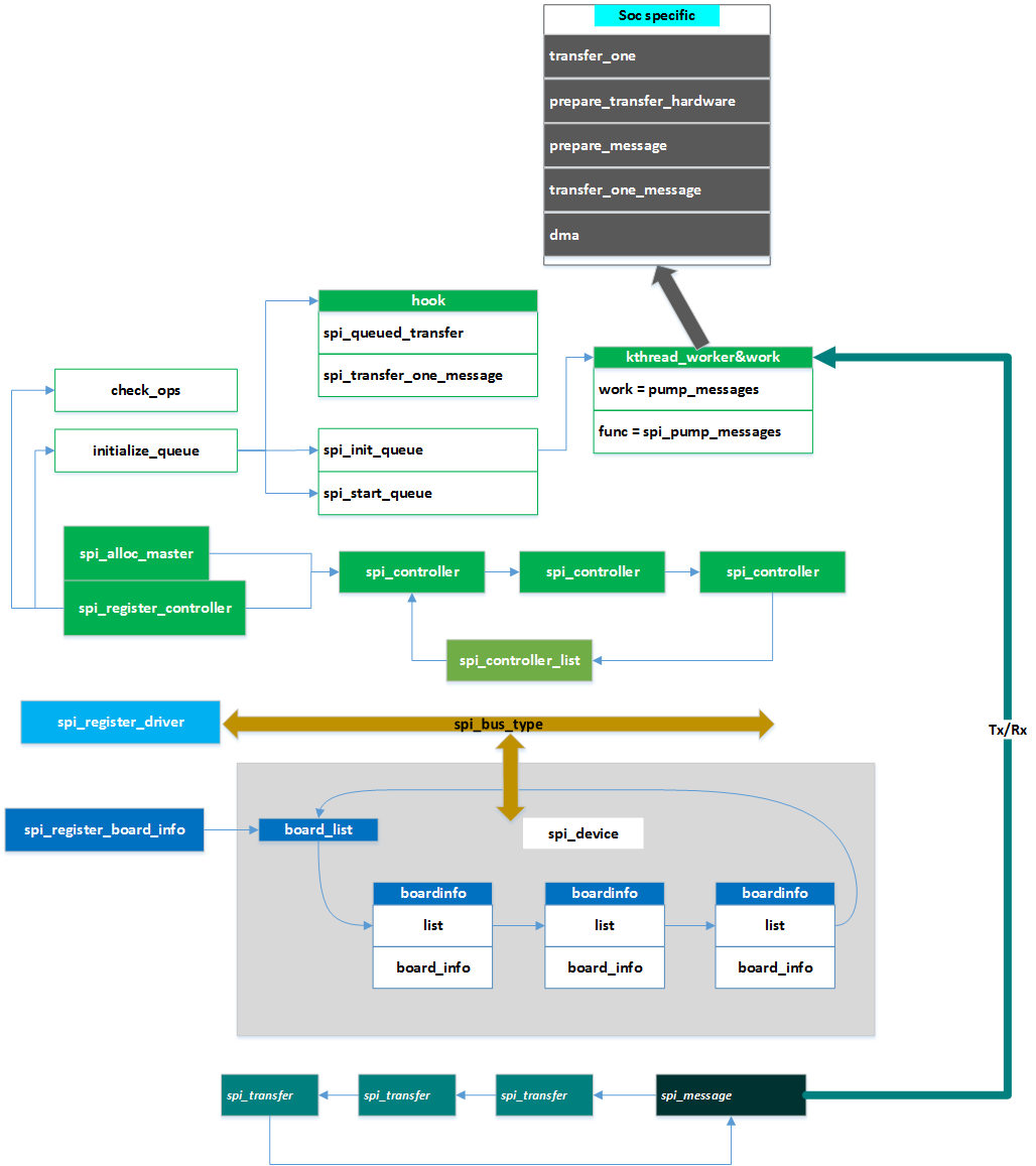
参考文章:
[2] SPI Subsystem -2- (Driver)
[3] Linux·SPI驱动分析和实例
[6] linux设备驱动 spi详解3-控制器驱动层(spi控制器)
[7] linux设备驱动 spi详解4-spi的数据传输流程
[8] linux设备驱动 spi详解5-应用到驱动的完整流程
[10]Linux SPI驱动框架理解
[13]Linux SPI 驱动分析(2)— 框架层源码分析(部分转载)

 浙公网安备 33010602011771号