
思科交换机配置
基础命令配置
telnet配置
交换机端配置: 1.Switch>enable 从用户模式进入特权模式 2.Switch#configure terminal 从特权模式进入全局配置模式 3.Switch(config)#hostname sw0 给交换机指定主机名为sw0 4.sw0(config)#username cisco password cisco 创建远程登录的用户名和密码 5.sw0(config)#line vty 0 4 指定vty线路并且进入线路配置模式 6.sw0(config-line)#login local 指定在登录时检查密码 7.sw0(config-line)#transport input telnet 开启Telnet服务 8.sw0(config-line)#exit 退出配置模式 9.sw0(config)#enable password 123456 设置特权模式非安全加密 10.sw0(config)#service password-encryption 设置密码加密 11.sw0(config)#interface vlan 1 进入vlan 1配置模式 12.sw0(config-if)#ip address 192.168.1.254 255.255.255.0 配置交换机管理IP地址和子网掩码 13.sw0(config-if)#no shutdown 启用接口 14.sw0(config-if)#exit 退出到上一层全局配置模式 15.sw0(config)#interface fastEthernet 0/1 指定接口并且进入接口配置模式 16.sw0(config)#switchport mode access 配置vlan 访问模式 17.sw0(config-if)#switchport access vlan 1 设置端口可以访问VLAN 1 18.sw0(config-if)#no shutdown 启用端口 19.sw0(config-if)#end 返回特权EXE模式 20.sw0#copy running-config startup-config 将运行配置作为启动配置存储到NVRAM中 (非易失性随机存储器) 客户端PC配置同网段IP和网关: 21.全局--FastEthernet--配置IP地址为192.168.1.99 22.全局--设置--网关设置成192.168.1.254,DNS服务器设置成114.114.114.114 ping测试连通性和Telnet远程登录交换机验证 23.PC打开桌面--命令提示符。 24.ping 192.168.1.254 25.telnet 192.168.1.254 输入用户名:cisco 输入密码:cisco 26.输入enable 输入特权EXEC模式的密码: 123456 27.查看当前配置: sw0#show running-confi
ssh配置
#配置域名 ip domain-name tyjz.com #配置密码 crypto key generate rsa #配置端口IP interface GigabitEthernet0/0/0 ip address 10.1.1.1 255.255.255.0 no shutdown #配置终端ssh服务,认证方式为本地用户密码登录 line vty 0 4 login local transport input ssh #配置本地用户密码以及用户优先级 username admin privilege 15 password 0 123456 #扩展知识 #查看rsa非对称秘钥 R2#show crypto key mypubkey rsa % Key pair was generated at: 0:11:31 UTC 三月 1 1993 Key name: R2.tyjz.com Storage Device: not specified Usage: General Purpose Key Key is not exportable. Key Data: 00005ac8 00001ce4 000013a3 00001661 00003ea7 00004404 00004a50 00000175 00001655 00001f7a 000008a9 00006b76 00002375 000067f2 00006bfe 0000667b 00003193 00007553 00007ceb 000067ca 000073ac 00003637 000018ef 1aed % Key pair was generated at: 0:11:31 UTC 三月 1 1993 Key name: R2.tyjz.com.server Temporary key Usage: Encryption Key Key is not exportable. Key Data: 00005af1 00003b9e 00001f5b 00006b08 00004ac8 00002ce3 0000656e 00003669 00004e14 000037ef 000035be 00006061 000031b6 000051ac 00005ed9 00003552 00002854 00005abc 0000152d 0000550a 00005b58 00007c6c 00002c25 174f
dhcp配置
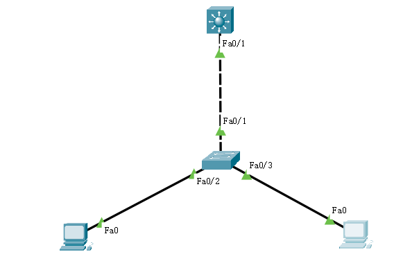
第一步:创建vlan,并进入vlan虚接口添加各自的IP地址,此IP地址就是DHCP的网关地址。 vlan 10 vlan 20 interface vlan 10 ip address 192.168.10.1 255.255.255.0 exit interface vlan 20 ip address 172.16.1.1 255.255.255.0 exit 第二步:创建vlan10的地址池: ip dhcp pool vlan10 network 192.168.10.0 255.255.255.0 default-router 192.168.10.1 dns-server 8.8.8.8 exit 第三步:创建vlan20的地址池: ip dhcp pool vlan20 network 172.16.1.0 255.255.255.0 default-router 172.16.1.1 dns-server 114.114.114.114 exit 第四步:将三层交换机的级联口设置为trunk模式,并允许vlan10和20通过,默认是允许所有vlan通过。 interface f0/1 switchport trunk encappsulation dot1q //设置此端口为trunk模式之前,将其封装。 switchport mode trunk switchport trunk allowed vlan 10-20 //允许通过的vlan标签,必须是一个范围,不然,后面的会覆盖前面的,导致后面的vlan可以获得IP,前面的获得失败. 第五步:接入交换机的配置: vlan 10 vlan 20 将不同的接口加入不同的vlan: interface f0/2 switchport mode access switchport access vlan 10 interface f0/3 switchport mode access switchport access vlan 20
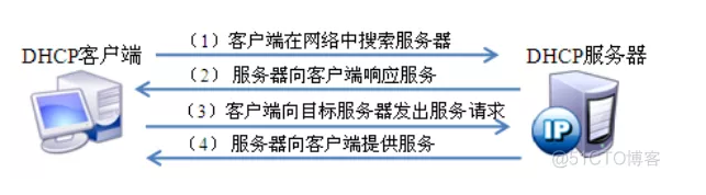
dhcp服务
- dhcp使用udp协议
- 端口号67、68
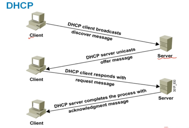
dhcp配置服务
(config)#service dhcp (config)#ip dhcp pool iteredu (dhcp-config)#network 192.168.1.0 255.255.255.0 (dhcp-config)#default-router 192.168.1.254 (dhcp-config)#domain-name iteredu.com (dhcp-config)#dns-server 61.134.1.4 61.134.1.5 (dhcp-config)#lease 7 #租约期 (config)#ip dhcp excluded-address 192.168.1.1 192.168.1.10
查看dhcp
show ip dhcp conflict #查看记录dhcp的IP冲突 show ip dhcp server statistics #查看dhcp状态 show ip dhcp binding #查看当前绑定的ip地址
NAT网络地址转换
-
用于修改IP数据包中的源、目的地址
-
为何使用NAT技术
- 节省IP地址(NAT+VLSM/CIDR)
- 安全考虑,隐藏内部真实IP
- NAT TCP负载均衡
- 解决地址冲突问题(公司合并)
NAT分类
-
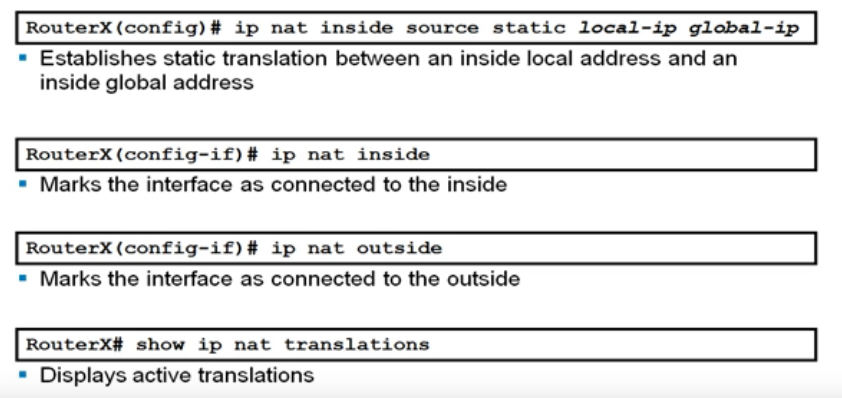
静态NAT
- 手工配置NAT映射表
- 一对一转换
-
动态NAT
- 定义地址池,动态创建NAT映射表
- 一对一转换

-
PAT(NAT Overload)
- 多对一转换
- 通过端口标识不同数据流
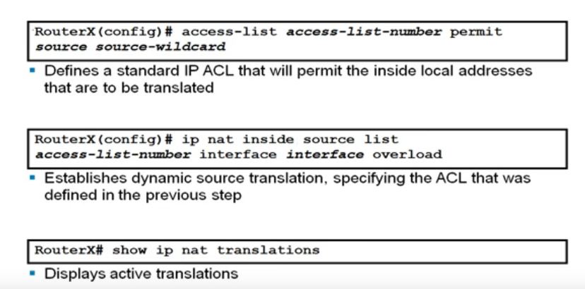
r1(config)#access-list 1 permit 192.168.1.0 0.0.0.255 r1(config)#ip nat inside source list 1 interface f0/1 overload r1(config)#int f0/1 //对外接口 r1(config-if)#ip nat outside r1(config-if)#int f0/0 //对内接口 r1(config-if)#ip nat inside
HSRP 热备份路由器协议
实验配置
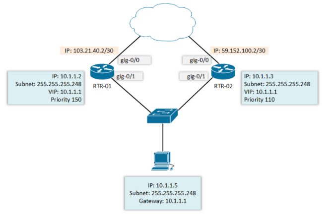
#R1基本配置 RTR-01 #configure terminal Enter configuration commands, one per line. End with CNTL/Z. RTR-01(config) # RTR-01(config) #interface gigabitEthernet 0/0 RTR-01(config-if) #ip address 103.21.40.2 255.255.255.252 RTR-01(config-if) #no shutdown RTR-01(config-if) #exit RTR-01(config) # RTR-01(config) #interface gigabitEthernet 0/1 RTR-01(config-if) #ip address 10.1.1.2 255.255.255.248 RTR-01(config-if) #no shutdown #R2基本配置 RTR-02(config) # RTR-02(config) #interface gigabitEthernet 0/0 RTR-02(config-if) #ip add 59.152.100.2 255.255.255.0 RTR-02(config-if) #no shutdown RTR-02(config-if) #exit RTR-02(config) # RTR-02(config) #interface gigabitEthernet 0/1 RTR-02(config-if) #ip add 10.1.1.3 255.255.255.248 RTR-02(config-if) #no shutdown #HSRP相关配置 RTR-01(config) #interface gigabitEthernet 0/1 RTR-01(config-if) #standby 1 ip 10.1.1.1 RTR-01(config-if) #standby 1 priority250 RTR-01(config-if) # RTR-02(config) #interface gigabitEthernet 0/1 RTR-02(config-if) #standby 1 ip 10.1.1.1 RTR-02(config-if) #standby 1 priority150 RTR-02(config-if) # #查看一下HSRP的相关配置情况 RTR-01 #show standby GigabitEthernet0/1 - Group 1 State is Active 2 state changes, last state change 00:02:42 Virtual IP address is 10.1.1.1 Active virtual MAC address is 0000.0c07.ac01 Local virtual MAC address is 0000.0c07.ac01 (v1 default) Hello time 3 sec, hold time 10 sec Next hello sent in0.656 secs Preemption disabled Active router is local Standby router is 10.1.1.3, priority 150 (expires in11.440 sec) Priority 250 (configured 250) Group name is "hsrp-Gi0/1-1"(default) RTR-01 # RTR-02 #show standby GigabitEthernet0/1 - Group 1 State is Standby 1 state change, last state change 00:00:48 Virtual IP address is 10.1.1.1 Active virtual MAC address is 0000.0c07.ac01 Local virtual MAC address is 0000.0c07.ac01 (v1 default) Hello time 3 sec, hold time 10 sec Next hello sent in1.056 secs Preemption disabled Active router is 10.1.1.2, priority 250 (expires in8.928 sec) Standby router is local Priority 150 (configured 150) Group name is "hsrp-Gi0/1-1"(default) RTR-02 #
VRRP和HSRP区别
1、两个都支持认证 2、两个都支持抢占,VRRP抢占默认开启 3、都可以做负载均衡(不同组之间) 4、HSRP中路由状态有6中,VRRP有3种 5、HSRP中叫做active路由器和standby路由器,VRRP叫做master路由器和backup路由器 6、HSRP standby路由器也主动发送hello包,这样HSRP活动路由器可以发现网络当中的备份路由器 VRRP backup路由器不主动发送hello包,所以master路由器不可以主动发现网络当中的backup路由器 7、HSRP虚拟路由器的Ip不能是活动路由器接口的ip,VRRP可以 8、HSRP是cisco私有,VRRP公有 9、HSRP支持追踪,VRRP不支持追踪 10、HSRP的standby路由器选举只有优先级起作用,ip地址不起作用。 VRRP的活动路由器选举优先级和ip地址都起作用 11、HSRP的hello时间为3秒,间隔hold时间为10秒 VRRP中失效间隔时间是通告间隔时间的3倍,通告间隔时间默认1秒 12、VRRP支持辞职,HSRP不支持辞职(辞职是指将接口优先级改为0后不参加活动路由器的选举) 13、MAC:00-00-5e-00-01-01 VRRP 组播地址224.0.0.18 00-00-0c-07-ac-01 HSRP 组播地址 224.0.0.2
VTP VLAN中继协议
-
作用:实现vlan集中化配置
-
VTP工作模式3种:服务器模式,客户端模式,透明模式
-
所有的VLAN配置都在服务端完成的,创建、修改和删除vlan
-
VTP是二层协议,通过二层组播协议发送的,默认5分钟发送一次
-
客户端模式:自动和服务器端同步信息,为保证一致性,客户端不能创建或删除vlan
ACL访问控制列表
ACL基本原则
- 按顺序执行,由上至下,只要有一条满足,则不会继续查找。
- 任何ACL都有隐含拒绝,如果都不匹配,那么一定匹配最后的隐含拒绝所有条目
- 在接口上应用ACL,in(进)或out(出)
ACL的类型
1.标准ACL: access-list-number编号1~99之间的整数,只针对源地址进行过滤。 2.扩展ACL: access-list-number编号100~199之间的整数,可以同时使用源地址和目标地址作为过滤条件,还可以针对不同的协议、协议的特征、端口号、时间范围等过滤。可以更加细微的控制通信量。 3.动态ACL 4.自反ACL 5.基于时间的ACL
ACL配置
-
标准ACL配置
配置标准ACL条目 Router(config)#access-list 1 deny 192.168.1.0 0.0.0.255 //创建一个编号为1的标准ACL条目,拒绝192.168.1.0网段 Router(config)#access-list 1 permit any //除192.168.1.0网段,都允许 在接口上应用ACL Router(config)#int se0/0/0 //进入接口 Router(config-if)#ip access-group 1 in //在接口上应用编号为1的ACL条目,并配置该接口为进口 -
扩展ACL配置
配置扩展ACL条目 Router(config)#access-list 101 deny tcp 192.168.2.0 0.0.0.255 host 172.16.2.1 eq www //创建一个编号为101的扩展ACL并拒绝192.168.2.0通过tcp端口80访问172.16.2.1www服务 Router(config)#access-list 101 permit ip any any //允许所有协议端口所有网段 在接口上应用ACL Router(config)#int se0/0/0 Router(config-if)#ip access-group 101 in Router(config-if)#exit R2(config)#access-list 110 deny tcp any host 192.168.100.10 eq www R2(config)#access-list 110 deny tcp any host 192.168.100.10 eq ftp R2(config)#int fa0/0 R2(config-if)#ip access-group 110 out
debug调试命令
Switch #debug ip icmp #查看icmp包 Switch #show debugging 显示当前各个调试开关的状态 Switch #debug all 打开系统所有的调试开关 Switch #undebug all 关闭所有的调试开关 Switch #debug aaa 打开AAA调试开关 Switch #debug acl 打开ACL调试开关 Switch #debug arp 打开ARP调试开关 Switch #debug dvmrp 打开DVMRP调试开关 Switch #debug filter 打开过滤器调试开关 Switch #debug igmp 打开IGMP调试开关 Switch #debug ip 打开IP调试开关 Switch #debug mstp 打开MSTP调试开关 Switch #debug multicast 打开多播数据流调试开关 Switch #debug pim 打开PIM调试开关 Switch #debug sys-guard 打开sys-guard调试开关 Switch #debug vlan 打开VLAN调试开关
其他查询命令
GW#sh cdp neighbors Capability Codes: R - Router, T - Trans Bridge, B - Source Route Bridge S - Switch, H - Host, I - IGMP, r - Repeater Device ID Local Intrfce Holdtme Capability Platform Port ID liantong Fas 0/1 151 R S I 3725#型号 Fas 0/0 dianxin Fas 0/0 167 R S I 3725 Fas 0/0 GW#sh cdp neighbors detail ------------------------- Device ID: liantong Entry address(es): IP address: 200.1.1.1 Platform: Cisco 3725, Capabilities: Router Switch IGMP Interface: FastEthernet0/1, Port ID (outgoing port): FastEthernet0/0 Holdtime : 125 sec Version : Cisco IOS Software, 3700 Software (C3725-ADVSECURITYK9-M), Version 12.4(25d), RELEASE SOFTWARE (fc1) Technical Support: http://www.cisco.com/techsupport Copyright (c) 1986-2010 by Cisco Systems, Inc. Compiled Wed 18-Aug-10 07:55 by prod_rel_team advertisement version: 2 VTP Management Domain: '' Duplex: half ------------------------- Device ID: dianxin Entry address(es): IP address: 100.1.1.1 Platform: Cisco 3725, Capabilities: Router Switch IGMP Interface: FastEthernet0/0, Port ID (outgoing port): FastEthernet0/0 Holdtime : 139 sec Version : Cisco IOS Software, 3700 Software (C3725-ADVSECURITYK9-M), Version 12.4(25d), RELEASE SOFTWARE (fc1) Technical Support: http://www.cisco.com/techsupport Copyright (c) 1986-2010 by Cisco Systems, Inc. Compiled Wed 18-Aug-10 07:55 by prod_rel_team advertisement version: 2 VTP Management Domain: '' Duplex: half
策略路由BDR
ospf路由表o标识
iegrp路由表i标识
外部路由表EX标识
静态路由策略
- 创建一个acl抓取路由条目:access-list 1 permit 202.10.1.1
- 创建一个route-map ToR3
- 然后在ToR3上抓取的acl条目:match ip address 1
- 在ToR3上确定吓一跳的路由ip:set ip next-hop 202.10.3.10
- 最后在流量的入接口上配置:ip policy route-map ToR3
ospf加入到EIGRP路由
在eigrp上配置重分布redistribute ospf 100 metric 10000 100 255 1 1500
配置
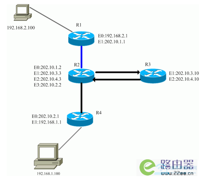
R2(config)# access-list 1 permit 202.10.1.1 //对来自202.10.1.1的包进行策略路由 R2(config)# route-map ToR3 //设置一个route-map,名称为'ToR3' R2(config-route-map)# match ip address 1 //对于符合访问列表1的的包(来自202.10.1.1的包) R2(config-route-map)# set ip next-hop 202.10.3.10 //设置下一跳为R3的E1端口IP R2(config-route-map)# int Ethernet 0/1 //切换至接口配置模式 R2(config-if)# ip policy route-map ToR3 //对该接口应用ToR3路由
查看命令
show route-map
路由协议
静态路由,SLA,BFD,ODR
静态路由+浮动路由+递归路由
-
Ping---- ping过去的包称为:echo包,ping回来的包echo-reply包
-
静态路由:就是手动写的一条条的路由条目
-
浮动路由:双线路备份
-
递归路由:
CEF:思科路快速转发(华为对于FIB)
- 思科设备默认启用cef,不查路由表,而查的是cef表,路由表是递归查询路由条目,查询速度较慢。cef表是根据路由表发生变化,cef表保存的信息一次查询到位,即只需要查询一次
- cef表是基于硬件转发,
路由优先级
-
华为设备
路由类型 direct OSPF IS-IS Static RIP IBGP OSPF ASE/import EBGP 优先级 0 10 15 60 100 130 150 170 -
思科设备
路由类型 Connected interface Static route EIGRP IGRP OSPF RIP External EIGRP Unknown 优先级 0 1 90 100 110 120 170 255 -
路由选择顺序:最长掩码匹配--------------路由优先级-----------------cost开销10的8此方除以带宽值
静态路由+SLA故障检测
思科私有协议,服务等级保障
案例1
实验目的
网关GW两条运营商线路电信和联通,默认走电信线路,如果电信断网将自动切换自联通线路
实验配置
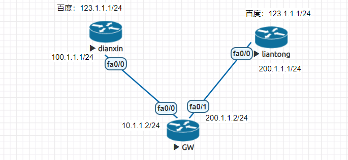
#dianxin hostname dianxin interface FastEthernet0/0 ip address 100.1.1.1 255.255.255.0 interface FastEthernet0/1 ip address 123.1.1.1 255.255.255.0 ------------------------------------------ #GW hostname GW ip sla monitor 1 #创建一个监控项 type echo protocol ipIcmpEcho 100.1.1.1 #ping跟踪的IP:100.1.1.1 #type http operation get url https://www.baidu.com #跟踪网址 frequency 5 #配置监测频率,5秒监测一次,实验设备是秒级,真实环境好的设备支持毫秒级 ip sla monitor schedule 1 life forever start-time now #配置生效时间,现在开始监控到永久,即立即生效 track 1 rtr 1 #定义track 1调用SLA 1 interface FastEthernet0/0 ip address 100.1.1.2 255.255.255.0 interface FastEthernet0/1 ip address 200.1.1.2 255.255.255.0 ip route 0.0.0.0 0.0.0.0 100.1.1.1 track 1 #静态路由调用track 1 ip route 0.0.0.0 0.0.0.0 200.1.1.1 10 #备路由,作用:在100.1.1.1出现故障中断的时候,会自动启用200.1.1.1这条路由 ----------------------------------------------- #liantong hostname liantong interface FastEthernet0/0 ip address 200.1.1.1 255.255.255.0 interface FastEthernet0/1 ip address 123.1.1.1 255.255.255.0
验证实验结果
GW#ping 123.1.1.1 repeat 1000 Type escape sequence to abort. Sending 1000, 100-byte ICMP Echos to 123.1.1.1, timeout is 2 seconds: !!!!!!!!!!!!!!!!!!!!!!!!!!!!!!!!!!!!!!!!!!!!!!!!!!!!!!!!!!!!!!!!!!!!!! !!!!!!....!!!!!!!!!!!!!!!!!!!!!!!!!!!!!!!!!!!!!!!!!!!!!!!!!!!!!!!!!!!! !!!!!!!!!!!! *Mar 1 05:11:11.250: %TRACKING-5-STATE: 1 rtr 1 state Up->Down!!!!!!!!!!!!!!!!!!!!!!!!!!!!!!!!!!!!!!!!!!!!!!!!!!!!!!!!!! !!!!!!!!!!!!!!!!!!!!!!!!!!!!!!!!!!!!!!!!!!!!!!!!!!!!!!!!!!!!!!!!!!!!!! !!!!!!!!!!!!!!!!!!!!!!!!!!!!!!!!!!!!!!!!!!!!!!!!!!!!!!!!!!!!!!!!!!!!!! !!!!!!!!!!!!!!!!!!!!!!!!!!!!!!!!!!!!!!!!!!!!!!!!!!!!!!!!!!!!!!!!!!!!!! !!!!!!!!!!!!!!!!!!!!!!!!!!!!!!!!!!!!!!!!!!!!!!!!!!!!!!!!!!!!!!!!!!!!! *Mar 1 05:11:16.250: %TRACKING-5-STATE: 1 rtr 1 state Down->Up! !!!!!!!!!!!!!!!!!!!!!!!!!!!!!!!!!!!!!!!!!!!!!!!!!!!!!!!!!!!!!!!!!!!!!! !!!!!!!!!!!!!!!!!!!!!!!!!!!!!!!!!!!!!!!!!!!!!!!!!!!!!!!!!!!!!!!!!!!!!! !!!!!!!!!!!!!!!!!!!!!!!!!!!!!!!!!!!!!!!!!!!!!!!!!!!!!!!!!!!!!!!!!!!!!! !!!!!!!!!!!!!!!!!!!!!!!!!!!!!!!!!!!!!!!!!!!!!!!!!!!!!!!!!!!!!!!!!!!!!! !!!!!!!!!!!!!!!!!!!!!!!!!!!!!!!!!!!!!!!!!!!!!!!!!!!!!!!!!!!!!!!!!!!!!! !!!!!!!!!!!!!!!!!!!!!!!!!!!!!!!!!!!!!!!!!!!!!!!!!!!!!!!!!!!!!!!!!!!!!! !!!!!!!!!!!!!!!!!!!!!!!!!!!!!!!!!!!!!!!!!!!!!!!!!!!!!!!!!!!!!!!!!!!!!! !!!!!!!!!!!!!!!!!!!! Success rate is 99 percent (996/1000), round-trip min/avg/max = 8/13/28 ms GW#sh ip sla monitor statistics Round trip time (RTT) Index 1 Latest RTT: 8 ms Latest operation start time: *05:11:34.290 UTC Fri Mar 1 2002 Latest operation return code: OK Number of successes: 28 Number of failures: 1 #失败一次 Operation time to live: Forever GW#sh track Track 1 Response Time Reporter 1 state State is Up #线路正常状态up 5 changes, last change 00:07:53 Latest operation return code: OK Latest RTT (millisecs) 8 Tracked by: STATIC-IP-ROUTING 0 GW#sh track Track 1 Response Time Reporter 1 state State is Down #线路中断状态down 6 changes, last change 00:00:00 Latest operation return code: Timeout Tracked by: STATIC-IP-ROUTING 0
实验案例二
实验目的
网关GW两条运营商线路电信和联通,默认走电信线路,如果电信断网将自动切换自联通线路,同时未防止网络抖动,电信断网延迟1S切换网络,电信网络恢复延迟10S再重新接入
实验配置
#dianxin hostname dianxin interface FastEthernet0/0 ip address 100.1.1.1 255.255.255.0 interface FastEthernet0/1 ip address 123.1.1.1 255.255.255.0 ------------------------------------------ #GW hostname GW ip sla monitor 1 #创建一个监控项 type echo protocol ipIcmpEcho 100.1.1.1 #ping跟踪的IP:100.1.1.1 #type http operation get url https://www.baidu.com #跟踪网址 frequency 5 #配置监测频率,5秒监测一次,实验设备是秒级,真实环境好的设备支持毫秒级 ip sla monitor schedule 1 life forever start-time now #配置生效时间,现在开始监控到永久,即立即生效 track 1 rtr 1 #定义track 1调用SLA 1 delay down 1 up 10 interface FastEthernet0/0 ip address 100.1.1.2 255.255.255.0 interface FastEthernet0/1 ip address 200.1.1.2 255.255.255.0 ip route 0.0.0.0 0.0.0.0 100.1.1.1 track 1 #静态路由调用track 1 ip route 0.0.0.0 0.0.0.0 200.1.1.1 10 #备路由,作用:在100.1.1.1出现故障中断的时候,会自动启用200.1.1.1这条路由 ----------------------------------------------- #liantong hostname liantong interface FastEthernet0/0 ip address 200.1.1.1 255.255.255.0 interface FastEthernet0/1 ip address 123.1.1.1 255.255.255.0
实验结果
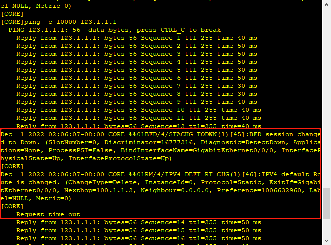
静态路由+BFD故障检测
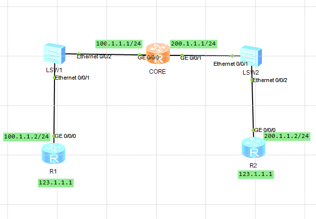
实验配置
#R1 sysname R1 interface GigabitEthernet0/0/0 ip address 100.1.1.2 255.255.255.0 interface LoopBack0 ip address 123.1.1.1 255.255.255.0 ---------------------------------------------- #CORE sysname CORE bfd interface GigabitEthernet0/0/0 ip address 100.1.1.1 255.255.255.0 interface GigabitEthernet0/0/1 ip address 200.1.1.1 255.255.255.0 bfd 1 bind peer-ip 100.1.1.2 interface GigabitEthernet0/0/0 one-arm-echo discriminator local 1 min-echo-rx-interval 100 commit ip route-static 0.0.0.0 0.0.0.0 200.1.1.2 preference 70 ip route-static 0.0.0.0 0.0.0.0 100.1.1.2 track bfd-session 1 ---------------------------------------------------------------------- #R2 sysname R2 interface GigabitEthernet0/0/0 ip address 200.1.1.2 255.255.255.0 interface LoopBack0 ip address 123.1.1.1 255.255.255.0
实验结果
- 关闭R1g0/0/0接口,CORE网络路由状态切换
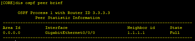
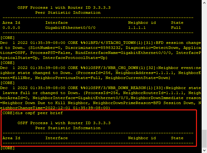
路由协议+BFD路由检测
实验配置
#CORE sysname CORE bfd interface GigabitEthernet0/0/0 ip address 100.1.1.1 255.255.255.0 interface GigabitEthernet0/0/1 ip address 200.1.1.1 255.255.255.0 ospf 1 router-id 3.3.3.3 bfd all-interfaces enable area 0.0.0.0 network 100.1.1.0 0.0.0.255 network 200.1.1.0 0.0.0.255 -------------------------------------------------- #R1 sysname R1 bfd interface GigabitEthernet0/0/0 ip address 100.1.1.2 255.255.255.0 interface LoopBack0 ip address 123.1.1.1 255.255.255.0 ospf 1 router-id 1.1.1.1 bfd all-interfaces enable area 0.0.0.0 network 100.1.1.0 0.0.0.255 network 123.1.1.0 0.0.0.255
实验结果
-
断开R1接口前状态
-
断开R2 g0/0/0接口后,断开端口间隔2s-3s内触发
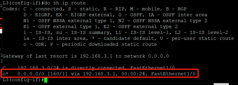
动态路由协议ODR(On Demand Routing)
- ODR是思科私有协议
- ODR是基于CDP协议
- 只能下发至对端设备
实验案例一
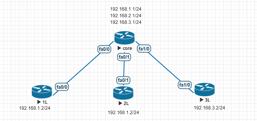
实验配置
#L1 hostname L1 interface FastEthernet0/0 ip address 192.168.1.2 255.255.255.0 ------------------------------------------------ #L2 hostname L2 interface FastEthernet0/1 ip address 192.168.2.2 255.255.255.0 ------------------------------------------------ #L3 hostname L3 interface FastEthernet1/0 ip address 192.168.3.2 255.255.255.0 ------------------------------------------------ #CORE hostname CORE interface FastEthernet0/0 ip address 192.168.1.1 255.255.255.0 interface FastEthernet0/1 ip address 192.168.2.1 255.255.255.0 interface FastEthernet1/0 ip address 192.168.3.1 255.255.255.0 router odr ------------------------------------------------
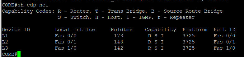
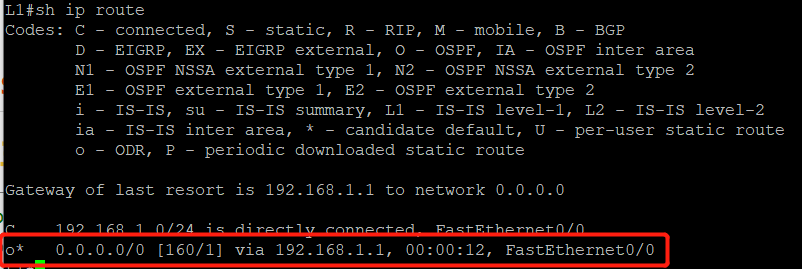
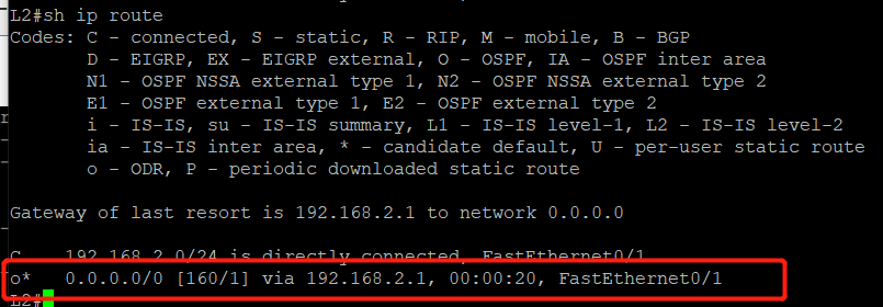
实验结果
ospf路由协议
简介: ospf(Open Shortest Path First )开放式最短路径优先协议
- 最大优点,开放式,所有厂商品牌设备均可用
- 性能上,根据带宽进行最优路径选择
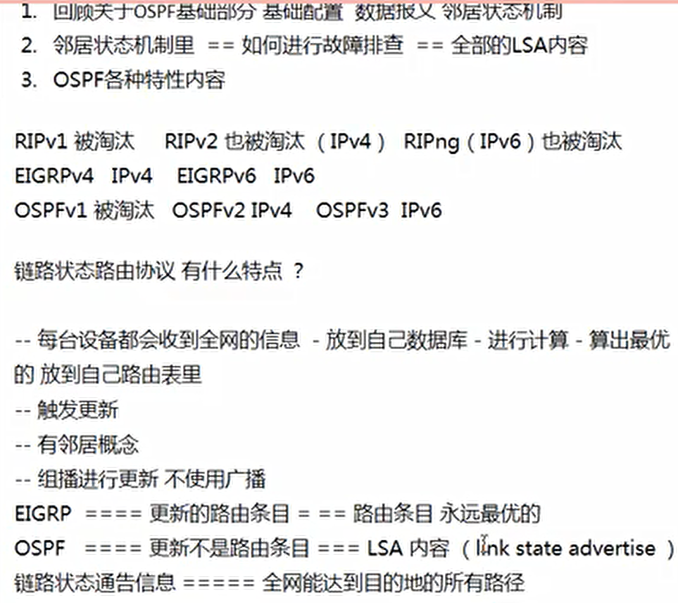
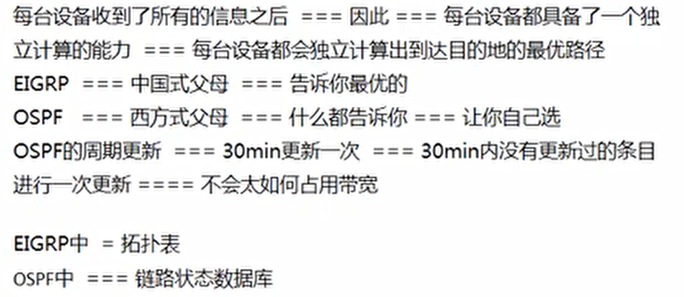
- 链路状态路由协议:每台设备都会收到全网信息并放到自己数据库进行计算最优的路径放到自己的路由表里,触发更新,建立邻居表,采用组播进行更新,不适应广播。
- 面向大型网络,网络设备数量较多
- 动态路由协议,彼此交换信息
- 动态更新,大量更新带来设备硬件消耗、负载
- 多区域,让一部分的信息只在自己区域内传递
- 减少部分信息的更新,更新并没有减少,详细
- ospf版本2,目前使用的ospf支持IPv4,ospf版本3能够支持IPv6
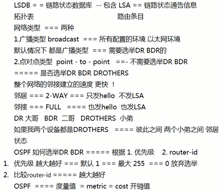
OSPF包结构

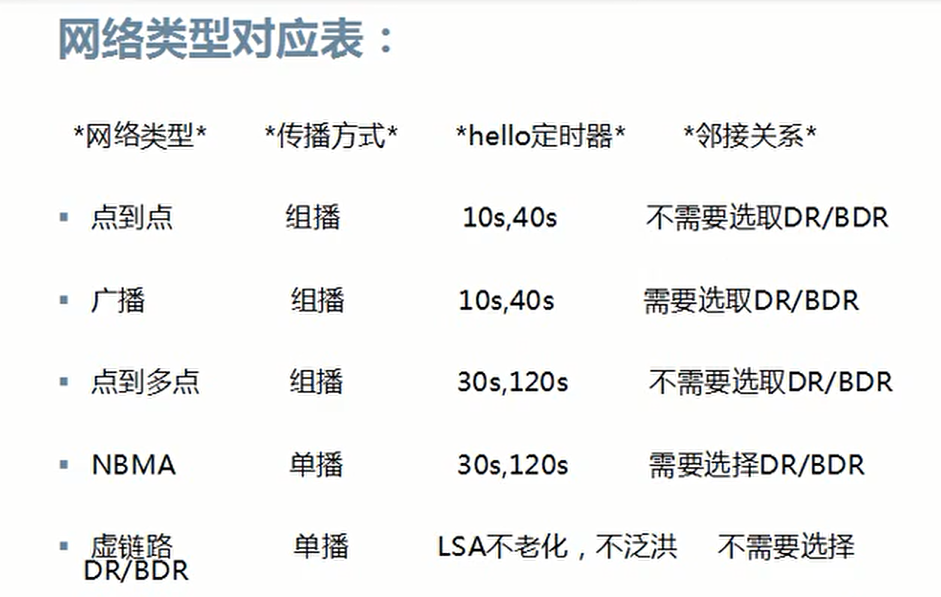
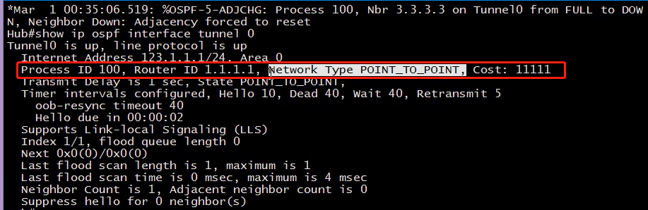
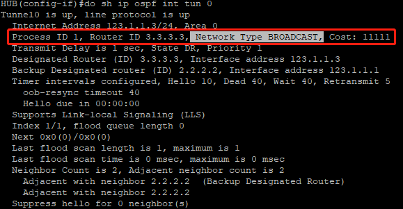
网络类型对应表
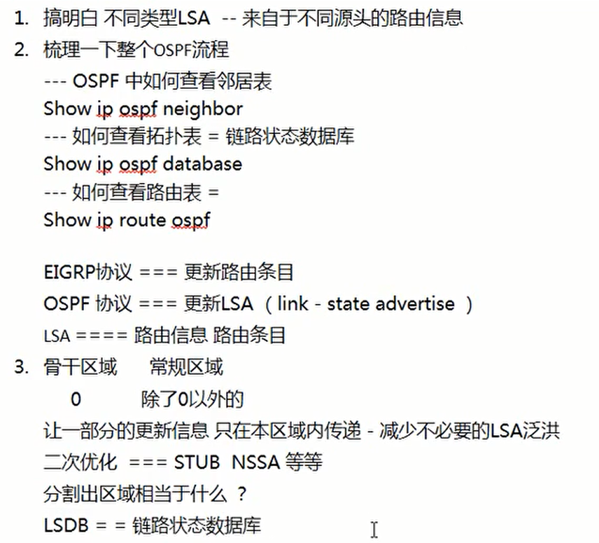
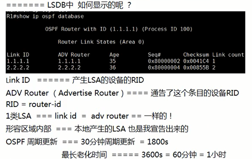
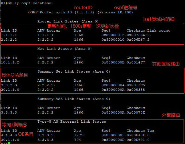
三个表查看

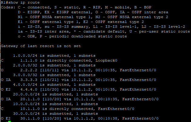
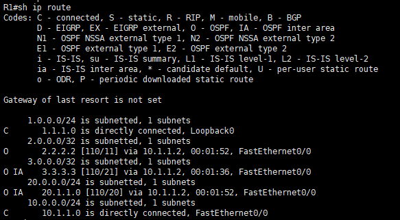
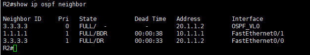
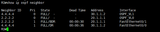
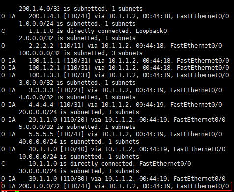
show ip ospf neighbor 查看邻居表 show ip ospf database 查看链路状态数据库 show ip route ospf 查看路由表 R1#sh ip ospf neighbor Neighbor ID Pri State Dead Time Address Interface 192.168.200.1 1 FULL/DR 00:00:38 100.1.1.2 FastEthernet0/0 ----------------------------------------------------------------------------------- R1#show ip ospf database OSPF Router with ID (192.168.100.1) (Process ID 1) Router Link States (Area 0) Link ID ADV Router Age Seq# Checksum Link count 192.168.100.1 192.168.100.1 819 0x80000003 0x005D75 2 192.168.200.1 192.168.200.1 820 0x80000003 0x00980C 2 Net Link States (Area 0) Link ID ADV Router Age Seq# Checksum 100.1.1.2 192.168.200.1 820 0x80000001 0x00C6D5 ------------------------------------------------------------------------------------ R1#show ip route ospf O 192.168.200.0/24 [110/20] via 100.1.1.2, 00:14:07, FastEthernet0/0
OSPF常用配置命令
Cisco(config)#router ospf 110 Cisco(config-router)#router-id 1.1.1.1 Cisco(config-router)#network 20.1.1.0 0.0.0.255 area 0 Cisco#show ip ospf neighbor Cisco(config)#int f0/0 Cisco(config-if)#ip ospf priority 1 Cisco(config-if)#ip ospf network broadcast //修改接口的网络类型 Cisco(config-if)#ip ospf network non-broadcast Cisco(config-if)#ip ospf network point-to-multipoint Cisco#show ip ospf interface Cisco(config)#int f0/0 Cisco(config-if)#ip ospf cost 100 //修改接口cost值 Cisco(config-if)#bandwidth 1000000 //修改参考带宽 Cisco(config-if)#ip ospf hello-interval 10 //修改hello间隔时间,死亡时间随之改变(4倍) Cisco(config)#router ospf 110 Cisco(config-router)#network 0.0.0.0 255.255.255.255 area 0 //宣告所有接口 Cisco#clear ip ospf process //清理OSPF进程 Cisco#show ip ospf //可查看到路由器ID,OSPF定时器以及LSA信息 Cisco#show ip route ospf //查看学习到的OSPF路由 Cisco#show ip protocols //显示路由协议参数 Cisco#debug ip ospf events //显示OSPF相关事件 Cisco#debug ip ospf adj //跟踪邻接关系的建立和终止 Cisco#debug ip ospf packet //查看正在传输的OSPF分组 Cisco#undebug all //关闭所有debug Cisco(config)#router ospf 110 Cisco(config-router)#passive-interface f0/1 //把接口变为被动接口 Cisco(config-router)#passive-interface default //把所有接口变为被动接口 Cisco(config)#int f0/0 Cisco(config-if)#ip ospf 110 area 0 //将接口宣告进OSPF Cisco#show ip ospf database //查看LSDB摘要信息 Cisco#show ip ospf database router //查看1类LSA的详细信息 Cisco#show ip ospf database router self-originate //查看自己生成的1类LSA的信息 Cisco#show ip ospf database network //查看2类LSA的详细信息 Cisco#show ip ospf database summary //查看3类LSA的详细信息 Cisco#show ip ospf database external //查看5类LSA的详细信息 Cisco#show ip ospf border-routers //查看5类LSA的详细信息 Cisco(config)#router ospf 1 Cisco(config-router)#network 10.1.1.0 0.0.0.255 area 1 Cisco(config-router)#area 1 stub //配置stub区域 Cisco(config-router)#area 1 default-cost 2 //修改下发的默认三类LSA的cost为2,默认为1 Cisco(config-router)#area 1 stub no-summary //配置完全stub区域 Cisco(config-router)#area 1 nssa //配置nssa区域 Cisco(config-router)#area 1 nssa default-information-originate //在NSSA区域的ABR上手工下发默认路由 Cisco(config-router)#area 1 nssa no-summary //配置完全nssa区域 Cisco(config-router)#area 1 nssa no-redistribution no-summary //配置完全nssa区域过滤7类LSA Cisco(config-router)#default-information originate //在OSPF中默认路由 Cisco(config-router)#default-information originate always //不论有没有静态默认路由,都向OSPF中注入默认路由 Cisco(config-router)#area 1 range 172.16.0.0 255.255.0.0 Cisco(config-router)#area 1 range 172.16.0.0 255.255.0.0 cost 1 //在ABR上对区域1中的1、2类明细路由进行汇总 Cisco(config-router)#summary-address 10.1.0.0 255.255.0.0 //在ASBR上对外部路由进行汇总 Cisco(config-router)#area 2 virtual-link 3.3.3.3 //配置虚链路 Cisco#show ip ospf virtual-links //查看虚链路 Cisco (config)#int f0/0 Cisco(config-if)#ip ospf authentication-key abc123 //配置OSPF认证密码 Cisco(config-if)#ip ospf authentication //启用OSPF接口认证 Cisco(config)#router ospf 110 Cisco(config-router)#area 0 authentication //启用OSPF区域认证 Cisco(config-if)#ip ospf message-digest-key 1 md5 abc123 //配置OSPF密文认证密码 Cisco(config-if)#ip ospf authentication message-digest //启用OSPF接口密文认证 Cisco(config)#router ospf 110 Cisco(config-router)#area 0 authentication message-digest //启用OSPF区域的密文认证 Cisco(config-router)#area 1 virtual-link 3.3.3.3 authentication-key abc123 Cisco(config-router)#area 1 virtual-link 3.3.3.3 authentication //配置OSPF虚链路的明文认证 Cisco(config-router)# area 1 virtual-link 3.3.3.3 authentication message-digest-key 1 md5 abc123 Cisco(config-router)#area 1 virtual-link 3.3.3.3 authentication message-digest //配置OSPF虚链路的密
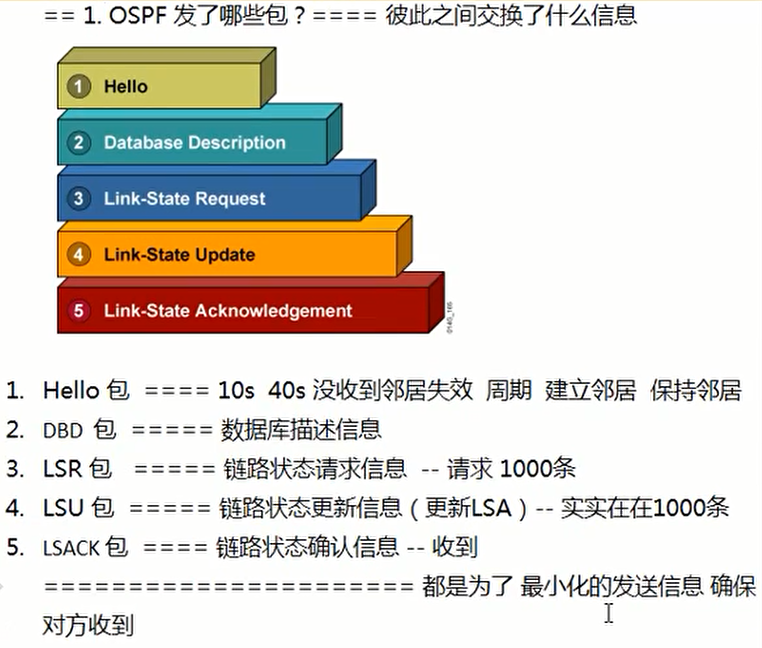
OSPF五种数据包报文
- Hello报文
- DD(Database Description)数据库描述报文
- LSR(LinkState Request)链路状态请求报文
- LSU(LinkState Update)链路状态更新报文
- LSAck(LinkState Acknowledgment)链路状态应答报文
OSPF Hello报文
- OSPF协议使用一种称之为Hello的报文来建立和维护相邻邻居路由器之间的临接关系。这个报文很简单,容量也很小,仅用来向邻居路由器证明自己的存在,就像人与人之间打招呼一样。
- Hello报文默认是以10s为周期,以组播方式向224.0.0.5组播组发送一次;但在P2MP和NBMA类型网络中OSPF默认是以60S为周期以单播形式向状态为down发送一个Hello报文(其他类型的hello报文是不会发送给状态为down的路由器的)。
- hello包10s发送一次,40s为死亡时间
OSPF DD报文
- DD报文用来描述本地路由器的链路状态数据库(LSDB),两个OSPF路由器初始化连接时需要交换DD报文,进行数据库同步。
- DD报文交换过程中以询问/应答方式进行,在DD报文交换中,一台为Master(主),一台为Slave(从)。Master路由器向Slave路由器发送它的路由表内容。但是显然,主、从之间的关系会因为每个DD交换的不同而不同,因为双方可能都有对方没有的LSA,网络中所有的路由器会在不同时刻担当不同的角色。
OSPF LSR报文
- LSR报文用于请求相邻路由器链路状态数据库的数据。当两台路由器互相交换完DD报文后,知道对端路由器有哪些LSA是本LSDB所没有的以及哪些LSA是失效的,则需要发送一个LSR报文,向对方请求所需的LSA。
OSPF LSU报文
- LSU报文是LSR请求报文的应答报文,用来向对端路由器发送所需的LSA内容。LSU是以组播方式将LSA泛洪出去的,并且对没有收到对方的确认应答,即LSAck报文(下面会讲)的LSA进行重传。
OSPF LSACK
- LSAck报文是路由器在收到对端发来的LSU报文后以单播或组播形式发出的确认报文,内容是需要确认的LSA头部。
OSPF建立邻居的几个问题
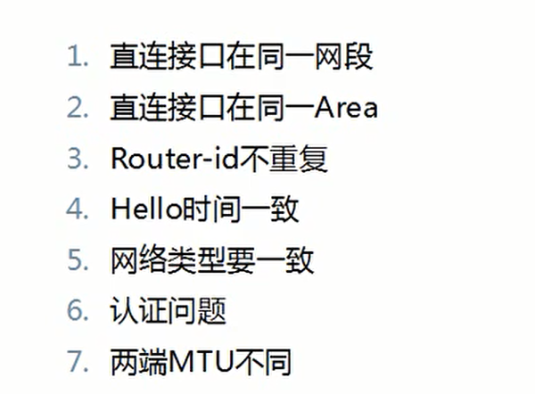
7种状态

OSPF区域类型
- 骨干区域Area 0——负责区域间路由传输
- 非骨干区域—根据能够学习的路由种类来区分
-标准区域
-末梢区域(stub)
-完全末梢(Totally stubby)区域
-非纯末梢区域(NSSA)
末梢区域和完全末梢区域
-
满足以下条件
1.只有一个默认路由作为其区域的出口
2.区域不能作为虚链路的穿越区域
3.Stub区域里无自治系统边界路由器ASBR
4.不是骨干区域Area 0 -
末梢区域
没有LSA4、5、7通告 -
完全末梢区域
除一条LSA3的默认路由通告外,没有LSA3、4、5、7通告 -
作用
末梢区域和完全末梢区域的作用:主要目的是减少区域内的LAS条目以及路由条目,减少对设备CPU和内存的占用,末梢区域和完全末梢区域中ABR会自动生成议题送默认路由发布到末梢区域或完全末梢区域中。
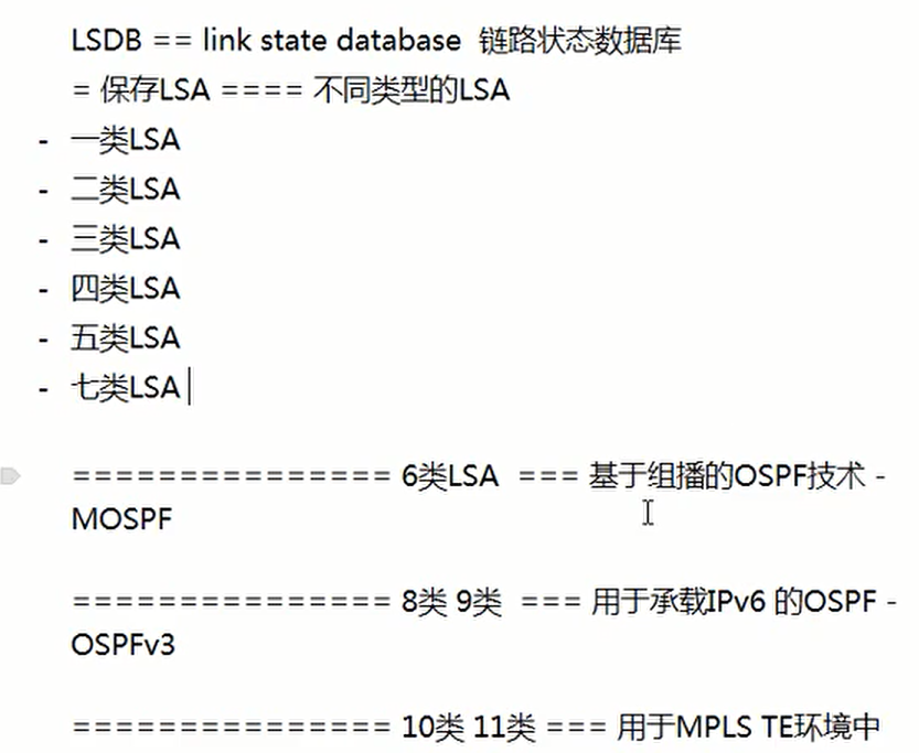
OSPF链路状态数据库的组成
- 每个路由器都创建了由每个接口、对应的相邻节点和接口速度组成的数据库。
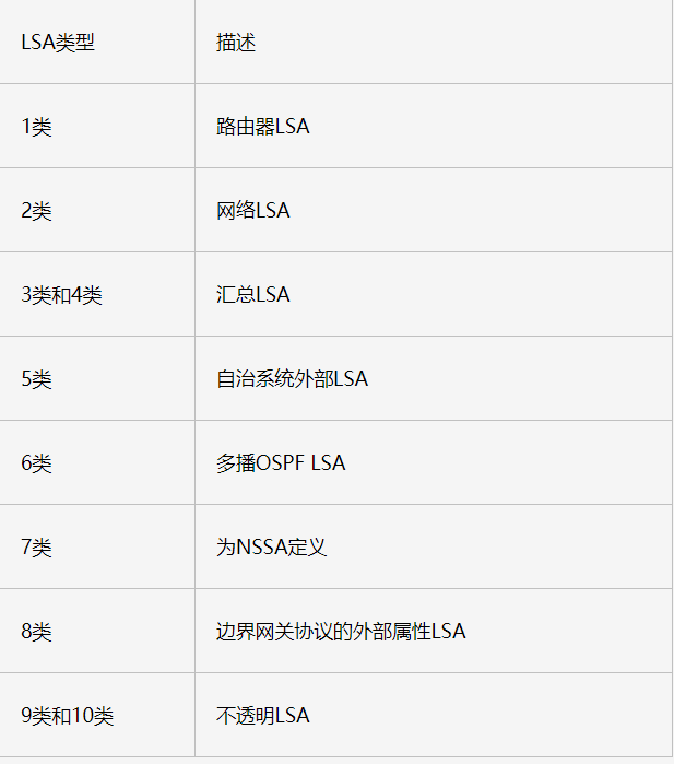
- 链路状态数据库中每个条目称为LSA(链路状态通告),常见的有六种LSA类型。
六种LSA类型
-
路由器LSA
由区域内的路由器发出的,描述路由器的链路状态和花费,传递到整个区域内。
-
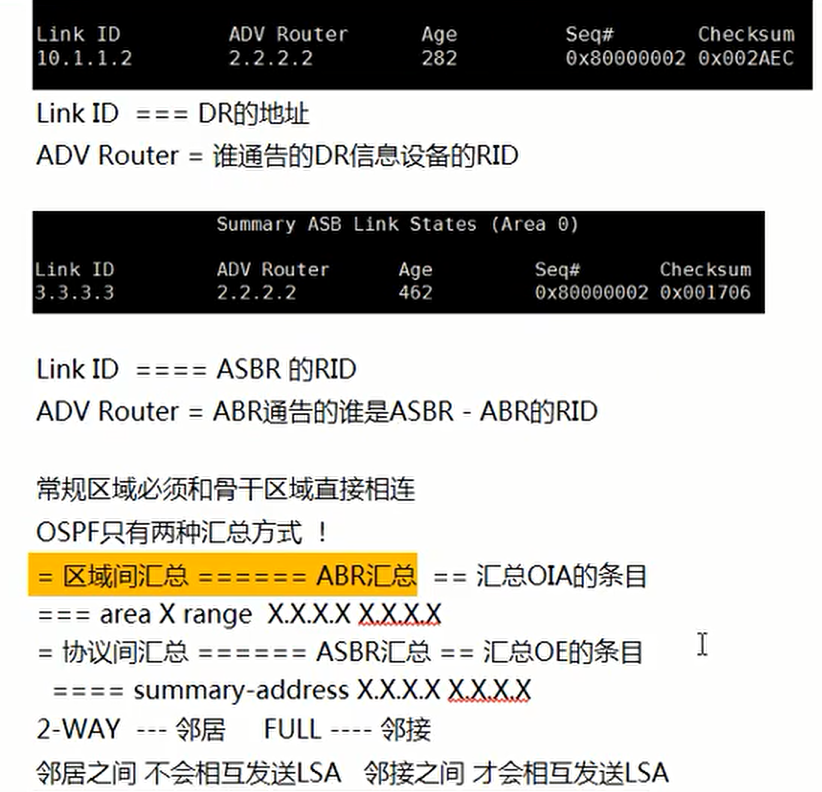
网络LSA
由区域内的DR发出的,描述了区域内变更信息,传递到整个区域内。
-
网络汇总LSA
ABR发出的,其他区域的汇总链路通告,描述了其他区域内某一网段的路由,区域间传递。
-
ASBR汇总LSA
ABR发出的,用于通告ASBR信息,确定ASBR的位置,不会出现在ASBR所属区域之内。
-
AS外部LSA
ASBR发出的,用于通告外部路由,告诉相同AS的路由器通往外部AS的路径,在整个AS中进行泛洪。
-
NSSA外部LSA
NSSA区域内的ASBR发出的,用于通告本区域连接的外部路由,与Type
5类似,仅在非纯末梢区域内进行泛洪,传递时会被ABR转换位LSA5。
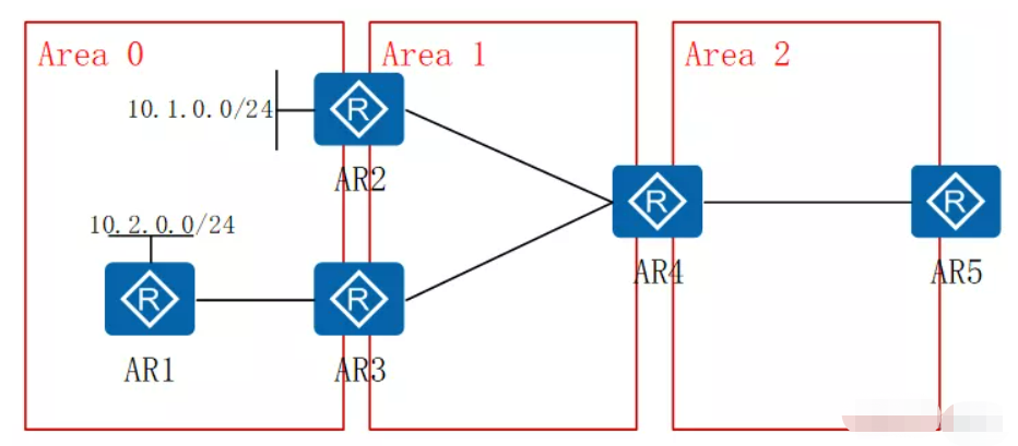
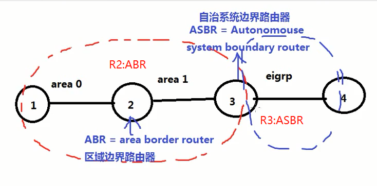
ABR Area Border Router,区域边界路由器
-
处于多个非骨干区域之间,比如处于Area 1和Area 2之间,比如图中的R4; -
处于骨干区域和非骨干区域之间,但在骨干区域里没有邻居,比如ABR在Area0有接口,但没有邻居,如图中的AR2; -
**处于骨干区域和非骨干区域之间,且在骨干区域里有邻居,这才是真正意义上的ABR,比如图中的AR3。**
ABR的定义及作用
-
定义:ABR处于区域边界间,限制LSA泛洪的范围。
-
作用:为本区域通告描述其他区域的网络,执行区域间路由通告、过滤、聚合等。
-
规则:
-
ABR1和ABR2是骨干区域Area 0和普通区域Area 1间的两台ABR,通过ABR1进入普通Area 1的LSA3路由,若ABR2在Area0有OSPF邻居,则该LSA3路由不进入ABR2的路由表(即不会通过Area1再通告进入Area0,ABR2有该路由也只能通过Area0的LSA1或LSA2学到); -
若ABR2在骨干区域Area 0没有邻居,仅有一个网络出现在骨干区域,则ABR1所通告的LSA3可以进入ABR2的路由表; -
没有出现在ABR路由表的路由是不会通告给其他区域的,这是边界的矢量特性。
如上图:
-
AR1的10.2.0.0/24路由是否出现在AR2里?
会,根据规则2,10.2.0.0/24可以出现在AR2里,因为AR2算不上真正的ABR。
-
AR2的10.1.0.0/24路由是否出现在AR1和AR3里?
都不会,根据规则1,AR3在骨干区域Area 0里有邻居,只会接受骨干区域的LSA3,不会收非骨干区域AR2发的经过非骨干区域访问骨干区域的LSA3 10.1.0.0/24路由,AR1里也没有改路由,根据规则3的矢量特性,AR3没有该路由,作为ABR是不会通告给其他区域的。当然,该路由会出现在AR4上。
-
AR4不是真正的ABR,因此能收到其他区域的路由,但不会向其他区域通告路由
-
ASBR:自治系统边界路由器
ASBR位于OSPF自治系统和非OSPF网络之间。ASBRs可以运行OSPF和另一路由选择协议(如RIP),把OSPF上的路由发布到其他路由协议上。发出的LSA5,用于向自治系统区域通告网络拓扑
好处
- 减少路由条目
- 避免骨干域过大,核心路由器压力过多
- 增强 OSPF 网络的稳定性 一个不稳定链路造成的不良影响,仅在同一个区中传播,不会影响到其他区域
- 每个区别内的LSA均只有自己区域内的,降低了域内的每个路由器的压力
- 3类LSA和路由聚合可以有效减少或避免某区域内的路由变化对整网带来路由震荡。这个在网络大的时候非常重要
弊端
- OSPF是链路状态算法,是loop free(无路由环路)的。这个链路状态算法只是在域内,而域间实质上是DV算法。为了避免路由环路,就有了所有非骨干区域必须围绕area0来建立,而为了避免这个问题又引入了虚链接。
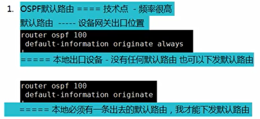
ospf默认路由
实验拓扑
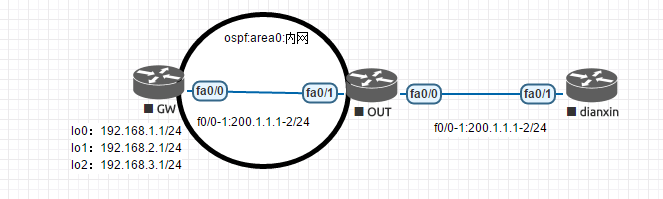
实验配置
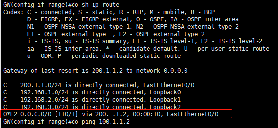
#GW hostname GW interface Loopback0 ip address 192.168.1.1 255.255.255.0 ip ospf 100 area 0 interface Loopback1 ip address 192.168.2.1 255.255.255.0 ip ospf 100 area 0 interface Loopback2 ip address 192.168.3.1 255.255.255.0 ip ospf 100 area 0 interface FastEthernet0/0 ip address 200.1.1.1 255.255.255.0 ip ospf 100 area 0 ------------------------------------------------ #OUT hostname OUT interface FastEthernet0/0 ip address 100.1.1.1 255.255.255.0 interface FastEthernet0/1 ip address 200.1.1.2 255.255.255.0 ip ospf 100 area 0 router ospf 100 default-information originate ip route 0.0.0.0 0.0.0.0 100.1.1.2 ------------------------------------------------------ #dianxin hostname DianXin interface FastEthernet0/1 ip address 100.1.1.2 255.255.255.0 ip route 0.0.0.0 0.0.0.0 100.1.1.1
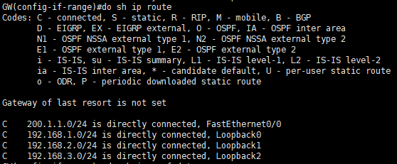
实验结果
-
配置默认路由前:GW路由条目
-
配置默认路由后:GW路由条目
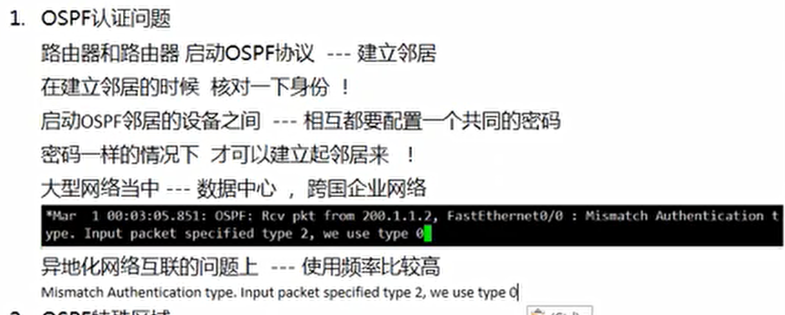
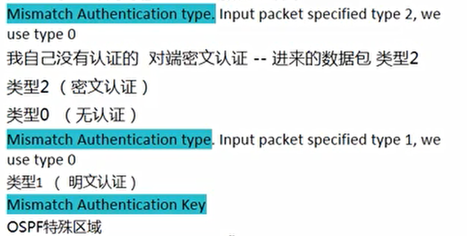
ospf认证问题
案例一:ospf明文认证
实验拓扑
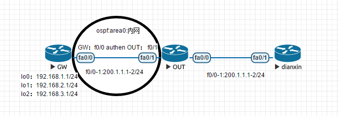
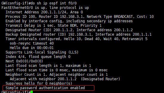
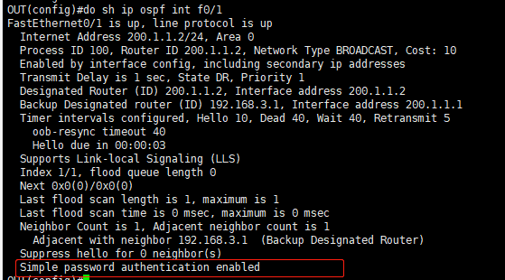
实验配置(明文认证)
#GW hostname GW interface Loopback0 ip address 192.168.1.1 255.255.255.0 ip ospf 100 area 0 interface Loopback1 ip address 192.168.2.1 255.255.255.0 ip ospf 100 area 0 interface Loopback2 ip address 192.168.3.1 255.255.255.0 ip ospf 100 area 0 interface FastEthernet0/0 ip address 200.1.1.1 255.255.255.0 ip ospf authentication ip ospf authentication-key cisco ip ospf 100 area 0 ------------------------------------------------ #OUT hostname OUT interface FastEthernet0/0 ip address 100.1.1.1 255.255.255.0 interface FastEthernet0/1 ip address 200.1.1.2 255.255.255.0 ip ospf authentication #启用明文认证 ip ospf authentication-key cisco #明文认证密码:cisco ip ospf 100 area 0 router ospf 100 default-information originate #ospf默认路由下发 ip route 0.0.0.0 0.0.0.0 100.1.1.2 ------------------------------------------------------ #dianxin hostname DianXin interface FastEthernet0/1 ip address 100.1.1.2 255.255.255.0 ip route 0.0.0.0 0.0.0.0 100.1.1.1
实验结果
-
GW:f0/0
-
OUT:f0/1
案例二:ospf密文认证
实验拓扑
实验配置(密文认证)
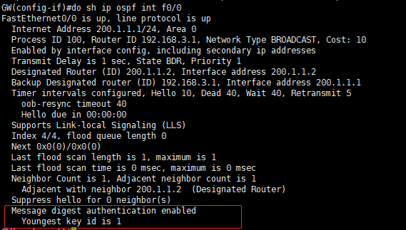
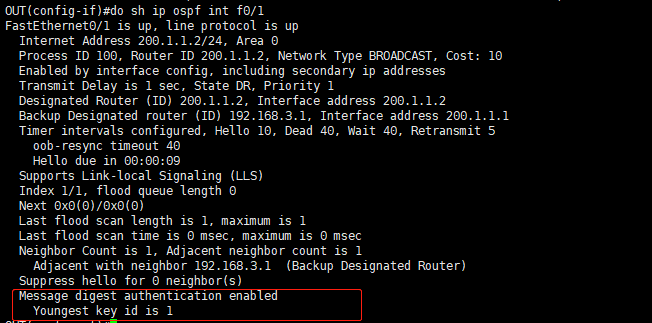
#GW hostname GW interface Loopback0 ip address 192.168.1.1 255.255.255.0 ip ospf 100 area 0 interface Loopback1 ip address 192.168.2.1 255.255.255.0 ip ospf 100 area 0 interface Loopback2 ip address 192.168.3.1 255.255.255.0 ip ospf 100 area 0 interface FastEthernet0/0 ip address 200.1.1.1 255.255.255.0 ip ospf authentication message-digest #启用密文认证 ip ospf message-digest-key 1 md5 cisco #密文认证第1把锁,认证密码:cisco ip ospf 100 area 0 ------------------------------------------------ #OUT hostname OUT interface FastEthernet0/0 ip address 100.1.1.1 255.255.255.0 interface FastEthernet0/1 ip address 200.1.1.2 255.255.255.0 ip ospf authentication message-digest #启用密文认证 ip ospf message-digest-key 1 md5 cisco #密文认证第1把锁,认证密码:cisco ip ospf 100 area 0 router ospf 100 default-information originate #ospf默认路由下发 ip route 0.0.0.0 0.0.0.0 100.1.1.2 ------------------------------------------------------ #dianxin hostname DianXin interface FastEthernet0/1 ip address 100.1.1.2 255.255.255.0 ip route 0.0.0.0 0.0.0.0 100.1.1.1
实验结果
案例三:ospf区域认证
实验拓扑
实验配置
#GW hostname GW interface Loopback0 ip address 192.168.1.1 255.255.255.0 ip ospf 100 area 0 interface Loopback1 ip address 192.168.2.1 255.255.255.0 ip ospf 100 area 0 interface Loopback2 ip address 192.168.3.1 255.255.255.0 ip ospf 100 area 0 interface FastEthernet0/0 ip address 200.1.1.1 255.255.255.0 ip ospf message-digest-key 1 md5 cisco #密文认证第1把锁,认证密码:cisco ip ospf 100 area 0 router ospf 100 area 0 authentication message-digest #启用密文认证 ------------------------------------------------ #OUT hostname OUT interface FastEthernet0/0 ip address 100.1.1.1 255.255.255.0 interface FastEthernet0/1 ip address 200.1.1.2 255.255.255.0 ip ospf message-digest-key 1 md5 cisco #密文认证第1把锁,认证密码:cisco ip ospf 100 area 0 router ospf 100 area 0 authentication message-digest #启用密文认证 default-information originate #ospf默认路由下发 ip route 0.0.0.0 0.0.0.0 100.1.1.2 ------------------------------------------------------ #dianxin hostname DianXin interface FastEthernet0/1 ip address 100.1.1.2 255.255.255.0 ip route 0.0.0.0 0.0.0.0 100.1.1.1
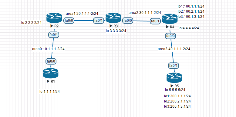
案例四:ospf虚链路认证
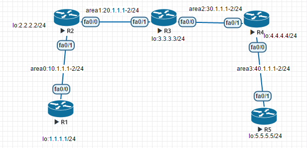
实验拓扑
实验配置
#R1 hostname R1 interface Loopback0 ip address 1.1.1.1 255.255.255.0 interface FastEthernet0/0 ip address 10.1.1.1 255.255.255.0 router ospf 100 network 1.1.1.0 0.0.0.255 area 0 network 10.1.1.0 0.0.0.255 area 0 ---------------------------------------- #R2 hostname R2 interface Loopback0 ip address 2.2.2.2 255.255.255.0 interface FastEthernet0/0 ip address 20.1.1.1 255.255.255.0 interface FastEthernet0/1 ip address 10.1.1.2 255.255.255.0 router ospf 100 area 1 virtual-link 3.3.3.3 authentication message-digest #虚链路开启密文认证 area 1 virtual-link 3.3.3.3 message-digest-key 1 md5 cisco #路链路设置第1把钥匙认证密码:cisco network 2.2.2.0 0.0.0.255 area 0 network 10.1.1.0 0.0.0.255 area 0 network 20.1.1.0 0.0.0.255 area 1 ---------------------------------------- #R3 hostname R3 interface Loopback0 ip address 3.3.3.3 255.255.255.0 interface FastEthernet0/0 ip address 30.1.1.1 255.255.255.0 interface FastEthernet0/1 ip address 20.1.1.2 255.255.255.0 router ospf 100 area 1 virtual-link 2.2.2.2 authentication message-digest #虚链路开启密文认证 area 1 virtual-link 2.2.2.2 message-digest-key 1 md5 cisco #路链路设置第1把钥匙认证密码:cisco area 2 virtual-link 4.4.4.4 authentication message-digest #虚链路开启密文认证 area 2 virtual-link 4.4.4.4 message-digest-key 1 md5 cisco #路链路设置第1把钥匙认证密码:cisco network 3.3.3.0 0.0.0.255 area 1 network 20.1.1.0 0.0.0.255 area 1 network 30.1.1.0 0.0.0.255 area 2 ---------------------------------------- #R4 hostname R4 interface Loopback0 ip address 4.4.4.4 255.255.255.0 interface FastEthernet0/0 ip address 40.1.1.1 255.255.255.0 interface FastEthernet0/1 ip address 30.1.1.2 255.255.255.0 router ospf 100 area 2 virtual-link 3.3.3.3 authentication message-digest #虚链路开启密文认证 area 2 virtual-link 3.3.3.3 message-digest-key 1 md5 cisco #路链路设置第1把钥匙认证密码:cisco network 4.4.4.0 0.0.0.255 area 2 network 30.1.1.0 0.0.0.255 area 2 network 40.1.1.0 0.0.0.255 area 3 ---------------------------------------- #R5 hostname R5 interface Loopback0 ip address 5.5.5.5 255.255.255.0 interface FastEthernet0/1 ip address 40.1.1.2 255.255.255.0 router ospf 100 network 5.5.5.0 0.0.0.255 area 3 network 40.1.1.0 0.0.0.255 area 3
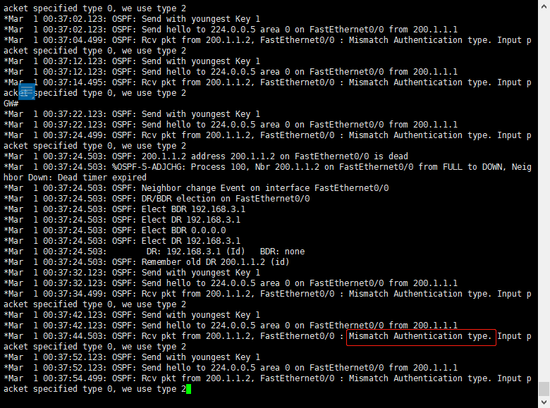
ospf故障认证排错
debug ip ospf events
ospf特殊区域
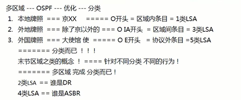
为什么要区分多区域
OSPF实验案例
实验一:以太网点对点网络类型
实验配置
#GW hostname GW interface Loopback0 ip address 192.168.1.1 255.255.255.0 ip ospf 100 area 0 interface Loopback1 ip address 192.168.2.1 255.255.255.0 ip ospf 100 area 0 interface Loopback2 ip address 192.168.3.1 255.255.255.0 ip ospf 100 area 0 interface FastEthernet0/0 ip address 200.1.1.1 255.255.255.0 ip ospf authentication ip ospf authentication-key cisco ip ospf 100 area 0 ------------------------------------------------ #OUT hostname OUT interface FastEthernet0/0 ip address 100.1.1.1 255.255.255.0 interface FastEthernet0/1 ip address 200.1.1.2 255.255.255.0 ip ospf 100 area 0 router ospf 100 ip ospf authentication ip ospf authentication-key cisco default-information originate #ospf默认路由下发 ip route 0.0.0.0 0.0.0.0 100.1.1.2 ------------------------------------------------------ #dianxin hostname DianXin interface FastEthernet0/1 ip address 100.1.1.2 255.255.255.0 ip route 0.0.0.0 0.0.0.0 100.1.1.1
实验二:ospf多区域和导入eigrp路由
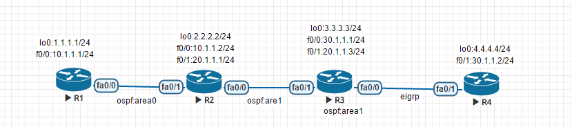
实验配置
#R1 hostname R1 interface Loopback0 ip address 1.1.1.1 255.255.255.0 interface FastEthernet0/0 ip address 10.1.1.1 255.255.255.0 no shutdown router ospf 100 network 1.1.1.0 0.0.0.255 area 0 network 10.1.1.0 0.0.0.255 area 0 -------------------------------------------- #R2 hostname R2 interface Loopback0 ip address 2.2.2.2 255.255.255.0 interface FastEthernet0/0 ip address 20.1.1.1 255.255.255.0 no shutdown interface FastEthernet0/1 ip address 10.1.1.2 255.255.255.0 no shutdown router ospf 100 network 2.2.2.0 0.0.0.255 area 0 network 10.1.1.0 0.0.0.255 area 0 network 20.1.1.0 0.0.0.255 area 1 -------------------------------------------- #R3 hostname R3 interface Loopback0 ip address 3.3.3.3 255.255.255.0 interface FastEthernet0/0 ip address 30.1.1.1 255.255.255.0 no shutdown interface FastEthernet0/1 ip address 20.1.1.2 255.255.255.0 no shutdown router eigrp 100 network 30.1.1.0 0.0.0.255 router ospf 100 redistribute eigrp 100 subnets #引入外部路由eigrp network 2.2.2.0 0.0.0.255 area 1 network 3.3.3.0 0.0.0.255 area 1 network 20.1.1.0 0.0.0.255 area 1 -------------------------------------------- #R4 hostname R4 interface Loopback0 ip address 4.4.4.4 255.255.255.0 no shutdown interface FastEthernet0/1 ip address 30.1.1.2 255.255.255.0 no shutdown router eigrp 100 network 4.4.4.0 0.0.0.255 network 30.1.1.0 0.0.0.255 no auto-summary ip route 0.0.0.0 0.0.0.0 30.1.1.1
实验结果
实验结论
- 单纯的多区域并没有减少路由表大小,没有实现优化的作用
实验三:ospf虚链路
- 虚链路作用:为了把其他区域直接连接到骨干区域
实验目的
- 多区域中,所有的非骨干区域路由器必须要与骨干区域相连,否则区域之间无法互通,为了解决非骨干区域无法连接骨干区域问题,通过虚链路实现与骨干区域的连接
- R1,R2属于骨干区域,R3为非骨干区域,R2和R3建立虚链路,实现R4非骨干区域路由器直连骨干区域,路由互通,同理再连接R3和R4虚链路,实现R5非骨干区域路由器直连骨干区域,路由互通
- 建立虚链路两端必须是双向的
实验配置
#R1 hostname R1 interface Loopback0 ip address 1.1.1.1 255.255.255.0 interface FastEthernet0/0 ip address 10.1.1.1 255.255.255.0 router ospf 100 network 1.1.1.0 0.0.0.255 area 0 network 10.1.1.0 0.0.0.255 area 0 ---------------------------------------- #R2 hostname R2 interface Loopback0 ip address 2.2.2.2 255.255.255.0 interface FastEthernet0/0 ip address 20.1.1.1 255.255.255.0 interface FastEthernet0/1 ip address 10.1.1.2 255.255.255.0 router ospf 100 area 1 virtual-link 3.3.3.3 #R2和R3建立虚链路 network 2.2.2.0 0.0.0.255 area 0 network 10.1.1.0 0.0.0.255 area 0 network 20.1.1.0 0.0.0.255 area 1 ---------------------------------------- #R3 hostname R3 interface Loopback0 ip address 3.3.3.3 255.255.255.0 interface FastEthernet0/0 ip address 30.1.1.1 255.255.255.0 interface FastEthernet0/1 ip address 20.1.1.2 255.255.255.0 router ospf 100 area 1 virtual-link 2.2.2.2 #R3和R2建立虚链路 area 2 virtual-link 4.4.4.4 #R3和R4建立虚链路 network 3.3.3.0 0.0.0.255 area 1 network 20.1.1.0 0.0.0.255 area 1 network 30.1.1.0 0.0.0.255 area 2 ---------------------------------------- #R4 hostname R4 interface Loopback0 ip address 4.4.4.4 255.255.255.0 interface FastEthernet0/0 ip address 40.1.1.1 255.255.255.0 interface FastEthernet0/1 ip address 30.1.1.2 255.255.255.0 router ospf 100 area 2 virtual-link 3.3.3.3 ##R4和R3建立虚链路 network 4.4.4.0 0.0.0.255 area 2 network 30.1.1.0 0.0.0.255 area 2 network 40.1.1.0 0.0.0.255 area 3 ---------------------------------------- #R5 hostname R5 interface Loopback0 ip address 5.5.5.5 255.255.255.0 interface FastEthernet0/1 ip address 40.1.1.2 255.255.255.0 router ospf 100 network 5.5.5.0 0.0.0.255 area 3 network 40.1.1.0 0.0.0.255 area 3
实验结果
未建立虚链路前R1的路由条目
建立虚链路后R1的路由条目
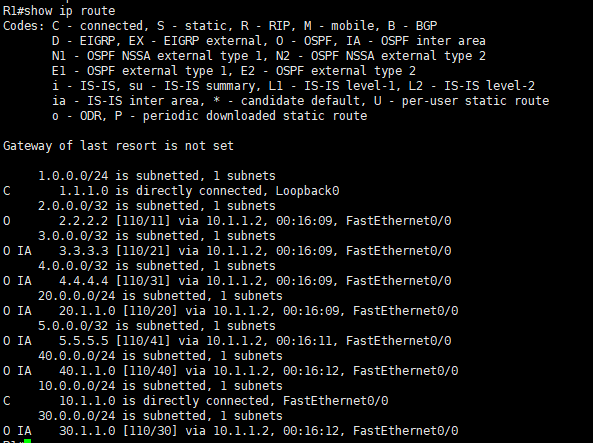
实验结论
1、虚链路必须是双向的 2、虚链路在ABR或ABRS设备中建立虚链路 3、在未建立虚链路的情况下,area0只能获取到相邻的ARB的路由条目 4、虚链路直接没有DR和DBR 5.虚链路的接口联系是ospf_VL+数字
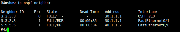
虚链路+路由汇总
实验说明
R4添加环回地址:100.1.1.1~3/24 R5添加环回地址:200.1.1.1~3/24 汇总R5:200.1.1.0路由条目,需要在R5直连的R4路由入接口上配置进行汇总:area 3 range 200.1.0.0 255.255.252.0
实验配置补充
#R4 int lo1 ip add 100.1.1.1 255.255.255.0 int lo2 ip add 100.1.2.1 255.255.255.0 int lo3 ip add 100.1.3.1 255.255.255.0 router ospf 100 area 3 range 200.1.0.0 255.255.252.0 #汇总200.1.1.0路由条目 net 100.1.1.0 0.0.0.255 area 2 net 100.1.2.0 0.0.0.255 area 2 net 100.1.3.0 0.0.0.255 area 2 ----------------------------------------- #R5 int lo1 ip add 200.1.1.1 255.255.255.0 int lo2 ip add 200.1.2.1 255.255.255.0 int lo3 ip add 200.1.3.1 255.255.255.0 router ospf 100 net 200.1.1.0 0.0.0.255 area 3 net 200.1.2.0 0.0.0.255 area 3 net 200.1.3.0 0.0.0.255 area 3 net 200.1.4.0 0.0.0.255 area 3
实验结果
-
路由未汇总前
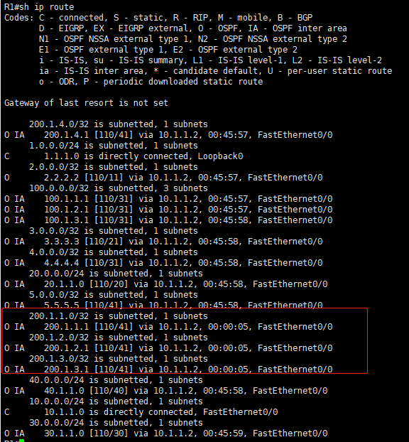
-
路由汇总后
ospf扩展知识
-
rip协议:RIPv1和RIPv2(基于IPv4)已淘汰,RIPng(IPv6)也被淘汰
-
EIGRP协议:IGRPv4(基于IPv4),IGRPv6(基于IPv6)
-
OSPF协议:OSPFfv1被淘汰,ospfv2(基于IPv4),ospfv3(基于IPv6)
-
ospf没有自动汇总,只能手动汇总,多区域下子,汇总方式在ABS和ABSR设备中汇总
-
ospf接口默认参考值,即接口带宽默认100Mbps, 如果实际带宽值为10M,那么该接口的cost=100/10=10
-
划分多区域的作用:优化路由条目
-
2-way状态属于邻居,full状态属于邻接,邻居状态只发hello包,邻接状态即发hello包也发LSA
-
ospf的routerID必须手动输入,自动输入可能因添加端口ip,ospf进程或设备重启后routerID可能会被替换
-
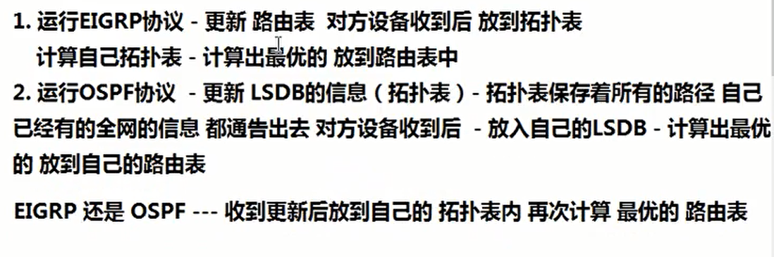
运行OSPF和EIGRP协议的区别
-
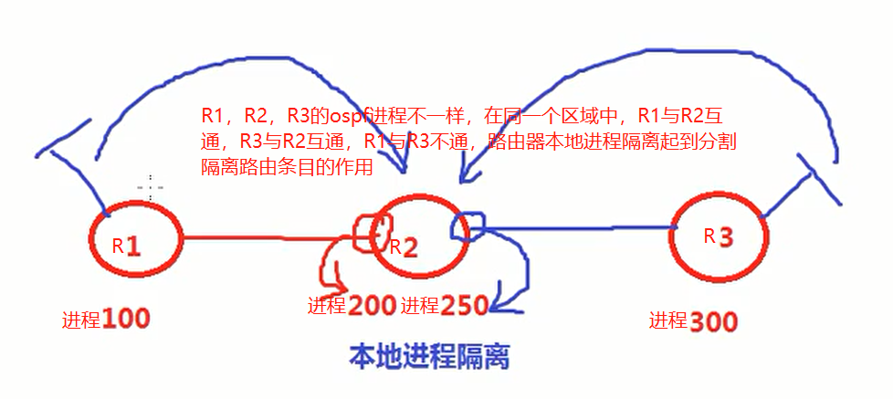
ospf进程不同作用:创建两个ospf进程的目前就是为了分割隔离两端路由不相互传递,如要互连可做重分布导入导出,或者ospf多个进程相互宣告可实现互通。
VPN
ipsecVPN
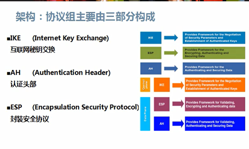

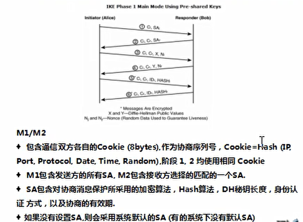
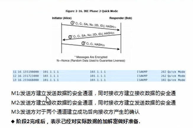
IKE
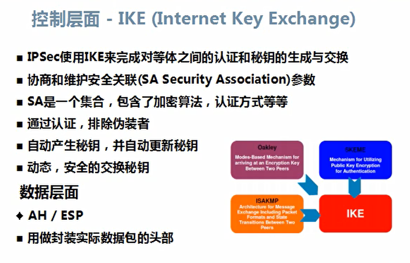
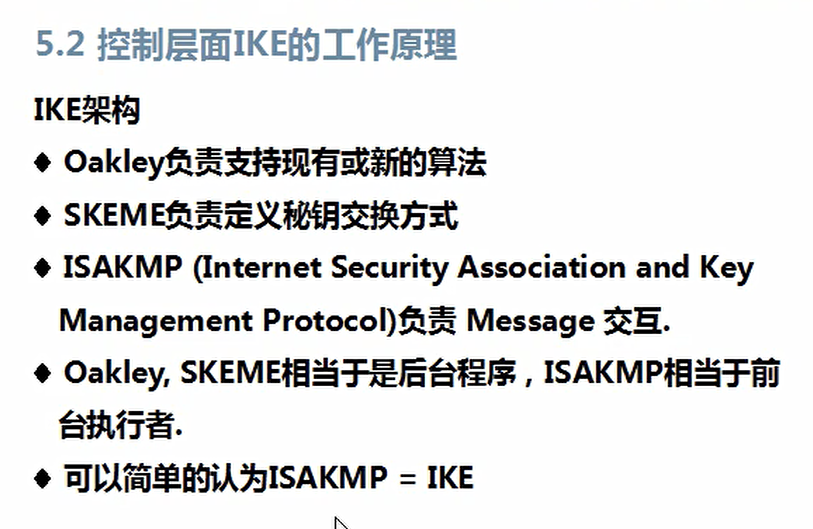
-
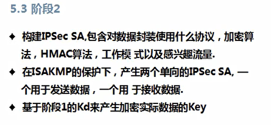
阶段一:保障数据信息的加密和私密性完整性
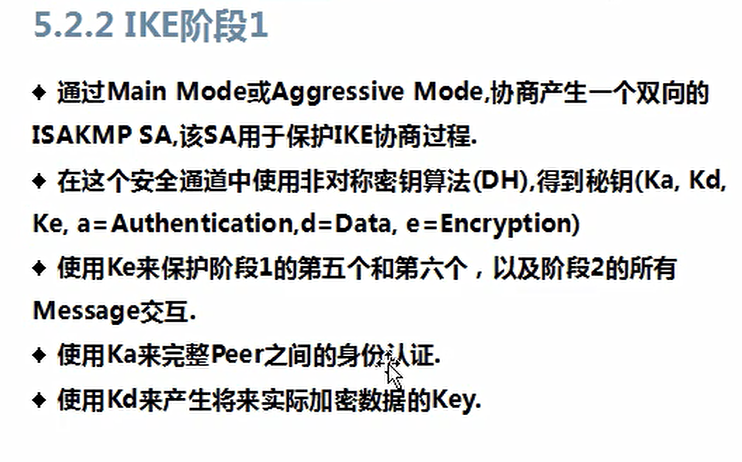
-
阶段二:保障实际数据的私密性和完整性


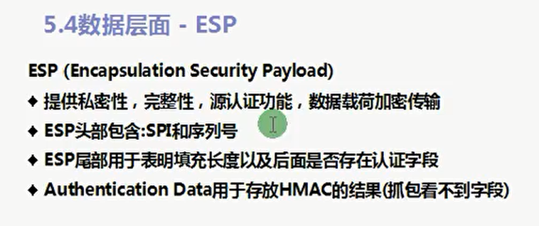
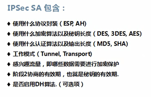
IPSec SA包含:
配置
R1(config)#crypto isakmp policy 10 R1(config-isakmp)#do show crypto isakmp policy Global IKE policy Protection suite of priority 10 encryption algorithm: DES - Data Encryption Standard (56 bit keys). hash algorithm: Secure Hash Standard authentication method: Rivest-Shamir-Adleman Signature Diffie-Hellman group: #1 (768 bit) lifetime: 86400 seconds, no volume limit R1(config-isakmp)#encryption 3des R1(config-isakmp)#hash md5 R1(config-isakmp)#group 2 R1(config-isakmp)#authentication pre-share R1(config-isakmp)#do show crypto isakmp policy Global IKE policy Protection suite of priority 10 encryption algorithm: Three key triple DES hash algorithm: Message Digest 5 authentication method: Pre-Shared Key Diffie-Hellman group: #2 (1024 bit) lifetime: 86400 seconds, no volume limit
案例
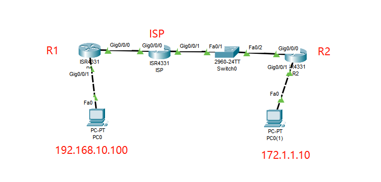
#R1 hostname R1 crypto isakmp policy 10 encr 3des authentication pre-share group 2 crypto isakmp key cisco address 200.1.1.2 crypto ipsec transform-set AA esp-3des esp-md5-hmac crypto map CCIE 10 ipsec-isakmp set peer 200.1.1.2 set transform-set AA match address 100 no ip domain-lookup interface Loopback0 ip address 192.168.20.1 255.255.255.0 no shutdown interface GigabitEthernet0/0/0 ip address 100.1.1.2 255.255.255.0 no shutdown crypto map CCIE interface GigabitEthernet0/0/1 ip address 192.168.10.1 255.255.255.0 ip route 0.0.0.0 0.0.0.0 100.1.1.1 access-list 100 permit ip 192.168.10.0 0.0.0.255 172.1.1.0 0.0.0.255 #ISP hostname ISP interface GigabitEthernet0/0/0 ip address 100.1.1.1 255.255.255.0 no shutdown interface GigabitEthernet0/0/1 ip address 200.1.1.1 255.255.255.0 no shutdown #R2 hostname R2 crypto isakmp policy 10 encr 3des authentication pre-share group 2 crypto isakmp key cisco address 100.1.1.2 crypto ipsec transform-set AA esp-3des esp-md5-hmac crypto map CCIE 10 ipsec-isakmp set peer 100.1.1.2 set transform-set AA match address 100 interface GigabitEthernet0/0/0 ip address 200.1.1.2 255.255.255.0 crypto map CCIE interface GigabitEthernet0/0/1 ip address 172.1.1.1 255.255.255.0 ip route 0.0.0.0 0.0.0.0 200.1.1.1 access-list 100 permit ip 172.1.1.0 0.0.0.255 192.168.10.0 0.0.0.255
DMVPN
案例:tunnel
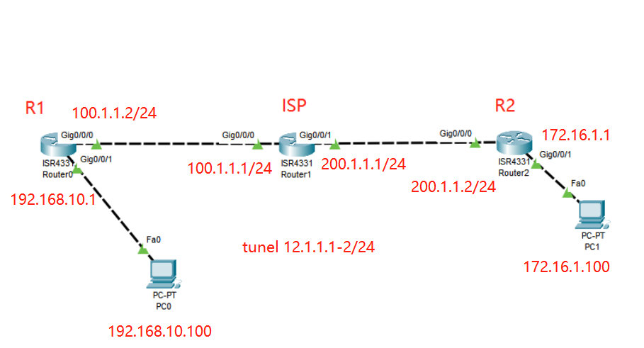
#R1 hostname R1 interface Tunnel0 ip address 12.1.1.1 255.255.255.0 mtu 1476 tunnel source GigabitEthernet0/0/0 tunnel destination 200.1.1.2 interface GigabitEthernet0/0/0 ip address 100.1.1.2 255.255.255.0 interface GigabitEthernet0/0/1 ip address 192.168.10.1 255.255.255.0 router ospf 1 router-id 1.1.1.1 log-adjacency-changes network 12.1.1.0 0.0.0.255 area 0 network 192.168.10.0 0.0.0.255 area 0 ip route 0.0.0.0 0.0.0.0 100.1.1.1 #ISP hostname ISP interface GigabitEthernet0/0/0 ip address 100.1.1.1 255.255.255.0 interface GigabitEthernet0/0/1 ip address 200.1.1.1 255.255.255.0 #R2 hostname R2 interface Tunnel0 ip address 12.1.1.2 255.255.255.0 mtu 1476 tunnel source GigabitEthernet0/0/0 tunnel destination 100.1.1.2 interface GigabitEthernet0/0/0 ip address 200.1.1.2 255.255.255.0 interface GigabitEthernet0/0/1 ip address 172.16.1.1 255.255.255.0 router ospf 1 router-id 2.2.2.2 log-adjacency-changes network 12.1.1.0 0.0.0.255 area 0 network 172.16.1.0 0.0.0.255 area 0 ip route 0.0.0.0 0.0.0.0 200.1.1.1
案例:DMVPM实验
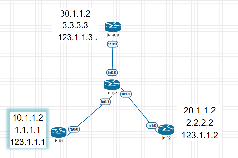
#HUB hostname HUB crypto isakmp policy 10 encr 3des authentication pre-share group 2 crypto isakmp key cisco address 0.0.0.0 0.0.0.0 crypto isakmp profile DZVPN crypto ipsec transform-set AA esp-3des esp-md5-hmac crypto ipsec profile DZVPN set transform-set AA interface Loopback0 ip address 3.3.3.3 255.255.255.0 interface Tunnel0 ip address 123.1.1.3 255.255.255.0 no ip redirects ip nhrp authentication cisco ip nhrp map multicast dynamic ip nhrp network-id 100 no ip split-horizon tunnel source 30.1.1.2 tunnel mode gre multipoint tunnel protection ipsec profile DZVPN ! interface FastEthernet0/0 ip address 30.1.1.2 255.255.255.0 router ospf 1 log-adjacency-changes network 30.1.1.0 0.0.0.255 area 0 ! router rip version 2 network 3.0.0.0 network 123.0.0.0 no auto-summary #R1 hostname R1 crypto isakmp policy 10 encr 3des authentication pre-share group 2 crypto isakmp key cisco address 0.0.0.0 0.0.0.0 crypto ipsec transform-set AA esp-3des esp-md5-hmac crypto ipsec profile DZVPN set transform-set AA interface Loopback0 ip address 1.1.1.1 255.255.255.0 interface Tunnel0 ip address 123.1.1.1 255.255.255.0 no ip redirects ip nhrp authentication cisco ip nhrp map 123.1.1.3 30.1.1.2 ip nhrp map multicast 30.1.1.2 ip nhrp network-id 100 ip nhrp nhs 123.1.1.3 tunnel source 10.1.1.2 tunnel mode gre multipoint tunnel protection ipsec profile DZVPN interface FastEthernet0/0 ip address 10.1.1.2 255.255.255.0 duplex auto speed auto router ospf 1 log-adjacency-changes network 10.1.1.0 0.0.0.255 area 0 ! router rip version 2 network 1.0.0.0 network 123.0.0.0 no auto-summary #R2 hostname R2 crypto isakmp policy 10 encr 3des authentication pre-share group 2 crypto isakmp key cisco address 0.0.0.0 0.0.0.0 crypto ipsec transform-set AA esp-3des esp-md5-hmac crypto ipsec profile DZVPN set transform-set AA interface Loopback0 ip address 2.2.2.2 255.255.255.0 interface Tunnel0 ip address 123.1.1.2 255.255.255.0 no ip redirects ip nhrp authentication cisco ip nhrp map 123.1.1.3 30.1.1.2 ip nhrp map multicast 123.1.1.3 ip nhrp map multicast 30.1.1.2 ip nhrp network-id 100 ip nhrp nhs 123.1.1.3 tunnel source 20.1.1.2 tunnel mode gre multipoint tunnel protection ipsec profile DZVPN interface FastEthernet1/0 ip address 20.1.1.2 255.255.255.0 router ospf 1 log-adjacency-changes network 20.1.1.0 0.0.0.255 area 0 ! router rip version 2 network 2.0.0.0 network 123.0.0.0 no auto-summary #ISP interface FastEthernet0/0 ip address 30.1.1.1 255.255.255.0 duplex auto speed auto interface FastEthernet0/1 ip address 10.1.1.1 255.255.255.0 duplex auto speed auto interface FastEthernet1/0 ip address 20.1.1.1 255.255.255.0 speed auto full-duplex router ospf 1 log-adjacency-changes network 10.1.1.0 0.0.0.255 area 0 network 20.1.1.0 0.0.0.255 area 0 network 30.1.1.0 0.0.0.255 area 0 HUB#sh crypto engine connections active ID Interface IP-Address State Algorithm Encrypt Decrypt 1 FastEthernet0/0 30.1.1.2 set HMAC_SHA+3DES_56_C 0 0 2 FastEthernet0/0 30.1.1.2 set HMAC_SHA+3DES_56_C 0 0 2001 FastEthernet0/0 30.1.1.2 set 3DES+MD5 0 56 2002 FastEthernet0/0 30.1.1.2 set 3DES+MD5 57 0 2003 FastEthernet0/0 30.1.1.2 set 3DES+MD5 0 33 2004 FastEthernet0/0 30.1.1.2 set 3DES+MD5 35 0 R1#sh crypto engine connections active ID Interface IP-Address State Algorithm Encrypt Decrypt 1 Tunnel0 123.1.1.1 set HMAC_SHA+3DES_56_C 0 0 2 FastEthernet0/0 10.1.1.2 set HMAC_SHA+3DES_56_C 0 0 2001 Tunnel0 10.1.1.2 set 3DES+MD5 0 54 2002 Tunnel0 10.1.1.2 set 3DES+MD5 53 0 2003 FastEthernet0/0 10.1.1.2 set 3DES+MD5 0 4 2004 FastEthernet0/0 10.1.1.2 set 3DES+MD5 3 0 R2#sh crypto engine connections active ID Interface IP-Address State Algorithm Encrypt Decrypt 1 Tunnel0 123.1.1.2 set HMAC_SHA+3DES_56_C 0 0 2 Tunnel0 123.1.1.2 set HMAC_SHA+3DES_56_C 0 0 2001 Tunnel0 20.1.1.2 set 3DES+MD5 0 3 2002 Tunnel0 20.1.1.2 set 3DES+MD5 4 0 2003 Tunnel0 20.1.1.2 set 3DES+MD5 0 37 2004 Tunnel0 20.1.1.2 set 3DES+MD5 35 0 HUB#sh crypto isakmp sa dst src state conn-id slot status 30.1.1.2 20.1.1.2 QM_IDLE 2 0 ACTIVE 30.1.1.2 10.1.1.2 QM_IDLE 1 0 ACTIVE R1#sh crypto isakmp sa dst src state conn-id slot status 30.1.1.2 10.1.1.2 QM_IDLE 1 0 ACTIVE 10.1.1.2 20.1.1.2 QM_IDLE 2 0 ACTIVE R2#sh crypto isakmp sa dst src state conn-id slot status 30.1.1.2 20.1.1.2 QM_IDLE 2 0 ACTIVE 10.1.1.2 20.1.1.2 QM_IDLE 1 0 ACTIVE
案例:DMVPM-EIGRP(只建隧道数据未加密)
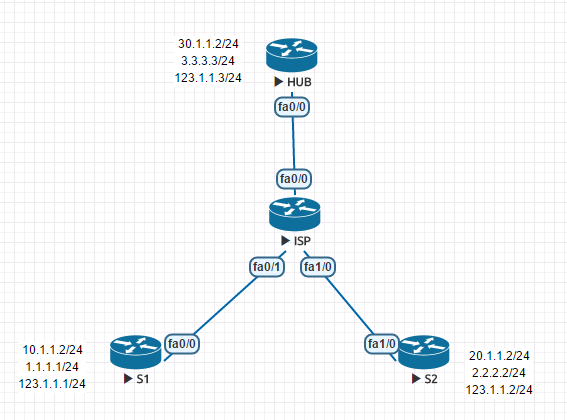
#HUB en conf t hostname HUB no ip domian-l int f0/0 ip add 30.1.1.2 255.255.255.0 no shutdown int lo0 ip add 3.3.3.3 255.255.255.0 interface Tunnel0 ip address 123.1.1.3 255.255.255.0 no ip redirects no ip next-hop-self eigrp 100 #距离矢量型协议会进行矢量叠加,这里要禁止修改下一跳 ip nhrp authentication cisco ip nhrp map multicast dynamic ip nhrp network-id 100 no ip split-horizon eigrp 100 #关闭水平分割 tunnel source 30.1.1.2 tunnel mode gre multipoint ip router 0.0.0.0 0.0.0.0 30.1.1.1 router eigrp 100 no auto-sum net 123.1.1.0 0.0.0.255 net 3.3.3.0 0.0.0.255 ----------------------------------------------------- #S1 en conf t hostname S1 no ip domian-l int f0/0 ip add 10.1.1.2 255.255.255.0 int lo0 ip add 1.1.1.1 255.255.255.0 interface Tunnel0 ip address 123.1.1.1 255.255.255.0 ip nhrp authentication cisco ip nhrp map 123.1.1.3 30.1.1.2 ip nhrp map multicast 30.1.1.2 ip nhrp network-id 100 ip nhrp nhs 123.1.1.3 tunnel source 10.1.1.2 tunnel mode gre multipoint ip router 0.0.0.0 0.0.0.0 30.1.1.1 router eigrp 100 no auto-sum net 123.1.1.0 0.0.0.255 net 1.1.1.0 0.0.0.255 ------------------------------------------------------- #S2 en conf t hostname S2 no ip domian-l int f1/0 ip add 20.1.1.2 255.255.255.0 no shutdown int lo0 ip add 2.2.2.2 255.255.255.0 interface Tunnel0 ip address 123.1.1.2 255.255.255.0 ip nhrp authentication cisco ip nhrp map 123.1.1.3 30.1.1.2 ip nhrp map multicast 30.1.1.2 ip nhrp network-id 100 ip nhrp nhs 123.1.1.3 tunnel source 20.1.1.2 tunnel mode gre multipoint ip router 0.0.0.0 0.0.0.0 20.1.1.1 router eigrp 100 no auto-sum net 123.1.1.0 0.0.0.255 net 2.2.2.0 0.0.0.255 ----------------------------------------------------------- #ISP en conf t hostname ISP no ip domain-lo int f0/0 ip add 30.1.1.1 255.255.255.0 no shutdown int f0/1 ip add 10.1.1.1 255.255.255.0 no shutdown int f1/0 ip add 20.1.1.1 255.255.255.0 no shutdown
案例:DMVPN-OSPF实验(建隧道和数据加密)
#HUB en conf t hostname HUB no ip domian-l int f0/0 ip add 30.1.1.2 255.255.255.0 no shutdown int lo0 ip add 3.3.3.3 255.255.255.0 crypto isakmp policy 10 encr 3des authentication pre-share group 2 crypto isakmp key cisco address 0.0.0.0 0.0.0.0 crypto isakmp profile DZVPN crypto ipsec transform-set AA esp-3des esp-md5-hmac crypto ipsec profile DZVPN set transform-set AA interface Tunnel0 ip address 123.1.1.3 255.255.255.0 ip nhrp authentication cisco ip nhrp map multicast dynamic ip nhrp network-id 100 ip ospf network broadcast tunnel source 30.1.1.2 tunnel mode gre multipoint tunnel protection ipsec profile DZVPN ip router 0.0.0.0 0.0.0.0 30.1.1.1 router ospf 1 router-id 3.3.3.3 network 3.3.3.0 0.0.0.255 area 0 network 123.1.1.0 0.0.0.255 area 0 ----------------------------------------------------- #S1 en conf t hostname S1 no ip domian-l int f0/0 ip add 10.1.1.2 255.255.255.0 no shutdown int lo0 ip add 1.1.1.1 255.255.255.0 crypto isakmp policy 10 encr 3des authentication pre-share group 2 crypto isakmp key cisco address 0.0.0.0 0.0.0.0 crypto isakmp profile DZVPN crypto ipsec transform-set AA esp-3des esp-md5-hmac crypto ipsec profile DZVPN set transform-set AA interface Tunnel0 ip address 123.1.1.1 255.255.255.0 ip nhrp authentication cisco ip nhrp map 123.1.1.3 30.1.1.2 ip nhrp map multicast 30.1.1.2 ip nhrp network-id 100 ip nhrp nhs 123.1.1.3 ip ospf network broadcast ip ospf priority 0 tunnel source 10.1.1.2 tunnel mode gre multipoint tunnel protection ipsec profile DZVPN ip router 0.0.0.0 0.0.0.0 30.1.1.1 router ospf 1 router-id 1.1.1.1 network 1.1.1.0 0.0.0.255 area 0 network 123.1.1.0 0.0.0.255 area 0 ------------------------------------------------------- #S2 en conf t hostname S2 no ip domian-l int f1/0 ip add 20.1.1.2 255.255.255.0 no shutdown int lo0 ip add 2.2.2.2 255.255.255.0 crypto isakmp policy 10 encr 3des authentication pre-share group 2 crypto isakmp key cisco address 0.0.0.0 0.0.0.0 crypto isakmp profile DZVPN crypto ipsec transform-set AA esp-3des esp-md5-hmac crypto ipsec profile DZVPN set transform-set AA interface Tunnel0 ip address 123.1.1.2 255.255.255.0 ip nhrp authentication cisco ip nhrp map 123.1.1.3 30.1.1.2 ip nhrp map multicast 30.1.1.2 ip nhrp network-id 100 ip nhrp nhs 123.1.1.3 ip ospf network broadcast ip ospf priority 0 tunnel source 20.1.1.2 tunnel mode gre multipoint tunnel protection ipsec profile DZVPN ip router 0.0.0.0 0.0.0.0 20.1.1.1 router ospf 1 router-id 2.2.2.2 network 2.2.2.0 0.0.0.255 area 0 network 123.1.1.0 0.0.0.255 area 0 ----------------------------------------------------------- #ISP en conf t hostname ISP no ip domain-lo int f0/0 ip add 30.1.1.1 255.255.255.0 no shutdown int f0/1 ip add 10.1.1.1 255.255.255.0 no shutdown int f1/0 ip add 20.1.1.1 255.255.255.0 no shutdown sh ip ospf int tunnel 0 sh ip ospf 1 database router
注意
-
ospf网络类型是point to point(点对点)表示同一时间只能建立一个ospf邻居,建立ospf网络类型各设备网络必须是一致类型
EZVPN
案例
配置一
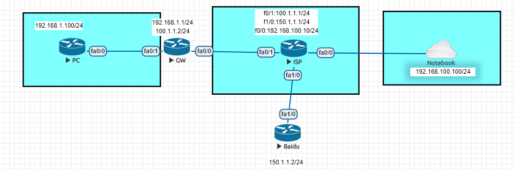
#PC hostname PC interface FastEthernet0/0 ip address 192.168.1.100 255.255.255.0 ip default-gateway 192.168.1.1 ----------------------------------------- #GW hostname GW aaa new-model #开启AAA模式 aaa authentication login RZ local #AAA登录本地认证,命名RZ aaa authorization network SQ local #AAA网络本地授权,命名SQ username admin password 0 cisco #本地用户名和密码,本地VPN认证的登录账号密码 crypto isakmp policy 10 #第1阶段IKE协商 encr 3des #加密模式为3des authentication pre-share #认证模式为预共享秘钥 group 2 #EZVPN必须设置为group模式为2 crypto isakmp client configuration group EZVPN #第1.5阶段的第二部分配置,客户端VPN接入的用户名:,EZVPN key cisco #VPN接入的认证密码:cisco dns 114.114.114.114 #接入客户端获取的DNS pool POOL #接入地址池 acl 100 #运行抓取的acl访问任何路由 max-users 2 #接入的最大用户数 crypto ipsec transform-set IPT esp-3des esp-md5-hmac #第二阶段ipsec协商配置 crypto dynamic-map DY 1 #建立第2阶段动态关联集 set transform-set IPT #动态映射表挂接阶段二 reverse-route #反向路由 #把所有配置汇总到一个MAP上,再挂接到接口上 crypto map MAP client authentication list SQ #映射客户端认证 crypto map MAP isakmp authorization list SQ crypto map MAP client configuration address respond #推送客户端IP地址 crypto map MAP 1 ipsec-isakmp dynamic DY # interface FastEthernet0/0 ip address 100.1.1.2 255.255.255.0 ip nat outside #nat外接口 crypto map MAP #出接口挂接MAP interface FastEthernet0/1 ip address 192.168.1.1 255.255.255.0 ip nat inside #nat内接口 ip local pool POOL 192.168.1.101 192.168.1.200 #定义分配拨号用户本地地址池 ip route 0.0.0.0 0.0.0.0 100.1.1.1 ip nat inside source list 1 interface FastEthernet0/0 overload #PAT的全局配置 access-list 1 permit 192.168.1.0 0.0.0.255 #PAT抓取的放行的list网段 access-list 100 permit ip 192.168.1.0 0.0.0.255 any #允许客户端这个网段访问任何地址 ---------------------------------------------------------- #ISP hostname ISP interface FastEthernet0/0 ip address 192.168.100.10 255.255.255.0 interface FastEthernet0/1 ip address 100.1.1.1 255.255.255.0 interface FastEthernet1/0 ip address 150.1.1.1 255.255.255.0 ---------------------------------------------------------------- #Baidu hostname Baidu interface FastEthernet1/0 ip address 150.1.1.2 255.255.255.0 ip default-gateway 150.1.1.1 ----------------------------------------------------- #notebook为一台PC虚拟机 IP:192.168.100.100/24 网关:192.168.100.10 #需安装思科VPN客户机软件:vpnclient-win-msi-5.0.04.0300-k9.exe #该实例vpn无法实现pc客户端telnet或其他服务访问到内网:192.168.1.0网段,因为GW网关做了NAT,把源地址转换为公网地址,导致路由不可达。 #ping包可以网络通的原因ping包不校验源目的IP地址,其他服务的tcp包需要tcp三次握手校验,一定会校验源目的地址,导致三次握手连接不起来。客户端加密虚拟网卡发送数据,结果是客户端真实网卡接手到数据导致无法建立TCP三次握手 #解决办法配置二,nat列表禁用vpn相互访问的网段,使得nat源IP地址反回流量不进行地址转换
-
放通ACL客户端获取内网ip地址的结果
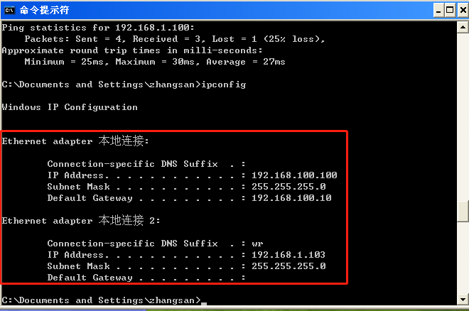
-
未放通ACL客户端获取内网ip的结果
配置二
#PC hostname PC interface FastEthernet0/0 ip address 192.168.1.100 255.255.255.0 ip default-gateway 192.168.1.1 ----------------------------------------- #GW hostname GW aaa new-model #开启AAA模式 aaa authentication login RZ local #AAA登录本地认证,命名RZ aaa authorization network SQ local #AAA网络本地授权,命名SQ username admin password 0 cisco #本地用户名和密码 crypto isakmp policy 10 #第1阶段IKE协商 encr 3des #加密模式为3des authentication pre-share #认证模式为预共享秘钥 group 2 #EZVPN必须设置为group模式为2 crypto isakmp client configuration group EZVPN #第1.5阶段的第二部分配置,客户端VPN接入的用户名:,EZVPN key cisco #VPN接入的认证密码:cisco dns 114.114.114.114 #接入客户端获取的DNS pool POOL #接入地址池 acl 101 #运行抓取的acl访问任何路由 max-users 2 #接入的最大用户数 crypto ipsec transform-set IPT esp-3des esp-md5-hmac #第二阶段ipsec协商配置 crypto dynamic-map DY 1 #第二阶段动态映射ipsec配置 set transform-set IPT #动态映射表挂接阶段二 reverse-route #反向路由 #把所有配置汇总到一个MAP上,再挂接到接口上 crypto map MAP client authentication list SQ #映射客户端认证 crypto map MAP isakmp authorization list SQ crypto map MAP client configuration address respond #推送客户端IP地址 crypto map MAP 1 ipsec-isakmp dynamic DY # interface FastEthernet0/0 ip address 100.1.1.2 255.255.255.0 ip nat outside #nat外接口 crypto map MAP #出接口挂接MAP interface FastEthernet0/1 ip address 192.168.1.1 255.255.255.0 ip nat inside #nat内接口 ip local pool POOL 192.168.1.101 192.168.1.200 #定义分配拨号用户本地地址池 ip route 0.0.0.0 0.0.0.0 100.1.1.1 ip nat inside source list 101 interface FastEthernet0/0 overload #PAT的全局配置 #PAT抓取的放行的list网段,该list禁用vpn网段返回流量转换为NAT出接口地址 access-list 100 deny ip 192.168.1.0 0.0.0.255 192.168.1.0 0.0.0.255 access-list 100 permit ip 192.168.1.0 0.0.0.255 any #允许客户端这个网段访问任何地址 access-list 101 permit ip 192.168.1.0 0.0.0.255 any ---------------------------------------------------------- #ISP hostname ISP interface FastEthernet0/0 ip address 192.168.100.10 255.255.255.0 interface FastEthernet0/1 ip address 100.1.1.1 255.255.255.0 interface FastEthernet1/0 ip address 150.1.1.1 255.255.255.0 ---------------------------------------------------------------- #Baidu hostname Baidu interface FastEthernet1/0 ip address 150.1.1.2 255.255.255.0 ip default-gateway 150.1.1.1 ----------------------------------------------------- #notebook为一台PC虚拟机 IP:192.168.100.100/24 网关:192.168.100.10 #需安装思科VPN客户机软件:vpnclient-win-msi-5.0.04.0300-k9.exe
NAT
缺点:非常耗费内存资料,每一个NAT条目占64k
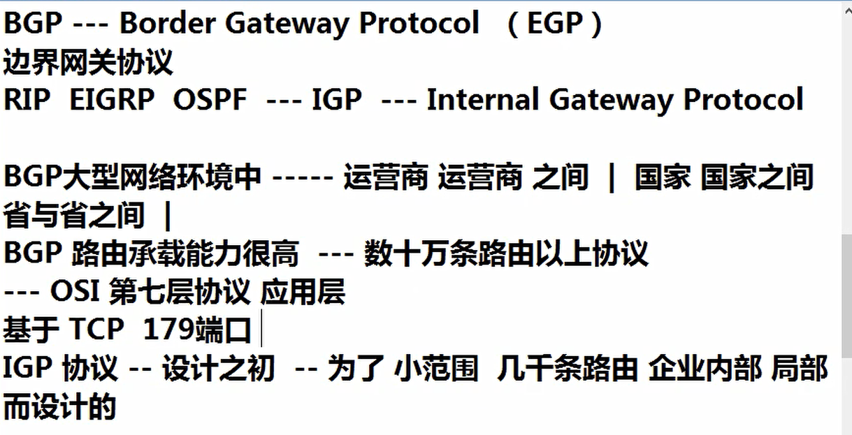
BGP协议
工作中注意事项
-
不要清除路由表,造成网络瘫痪
clear ip route * -
不要随便清除ospf进程,导致所有设备重新建立ospf邻居关系,造成网络瘫痪
clear ip ospf pro -
不要随便开启debug,容易造成设备资源超载系统崩溃
debug all -
虚拟服务器环境,一台物理服务器承载很多太虚拟机,那么接入物理服务器的交换机将承载多台虚拟机的mac地址,这个mac地址数量可能是巨大的。
本文作者:天梯的脚印
本文链接:https://www.cnblogs.com/zxl1024320609/p/16928427.html
版权声明:本作品采用知识共享署名-非商业性使用-禁止演绎 2.5 中国大陆许可协议进行许可。


【推荐】国内首个AI IDE,深度理解中文开发场景,立即下载体验Trae
【推荐】编程新体验,更懂你的AI,立即体验豆包MarsCode编程助手
【推荐】抖音旗下AI助手豆包,你的智能百科全书,全免费不限次数
【推荐】轻量又高性能的 SSH 工具 IShell:AI 加持,快人一步