
3_transport
存在的问题:
- TCP的IP地址在哪里?TCP的报文段中并没有IP地址,那么多路复用以及分用的IP地址在哪里?
传输层总体概述
传输层协议为运行在不同Host上的进程提供一种逻辑通信机制。
**逻辑通信机制: **两个个体在逻辑上是直接连接的,不考虑实际存在的影响因素:距离,路由器个数,物理媒介。
传输层与网络层的联系
多路复用和多路分用机制
作用
解决传输层的一个基本要求:将网络层的两个端系统之间的逻辑通信机制扩展到不同端系统上的逻辑通信机制。
扩展而言,多路复用以及多路分用可以出现在任意层上,其解决的问题更为宽泛的表示如下:
如果某层的一个 协议对应直接上层的多个协议/实 体,则需要复用/分用。
基本概念
多路复用:源主机从不同套接字中收集数据块,并为某个数据块分装上首部信息(一般为源和目的端口号,将用于多路分解)生成报文段,而后将报文段交付给下层应用传输。
多路分用:在接收端,传输层检查传输层报文段的信息,并分析分析出接受的套接字,进而将该报文段交付给正确的套接字。
该机制的实现
- 套接字有唯一标识符
- 每个报文段有特殊字段进行标识该报文段所要交付到的套接字
UDP多路复用和分解
- 一个UDP套接字由(IP地址,端口号)进行标识。
- 如果两个UDP报文段有不同的源IP地址和/或源端口号,但具有相同的目的IP地址和目的端口号,那么这两个报文段将通过相同的目的套接字被定向到相同的目的进程。(其中IP地址由网络层进行附加信息。)
- 对于报文段中的源端口号,其作为当前接受端向发送端发送数据的返回端口号的标识。
TCP多路复用和分解
- 一个TCP套接字由(源IP地址,源端口号,目的IP地址,目的端口号)进行标识。
- 如果两个TCP报文段有不同的源IP地址和/或源端口号,但具有相同的目的IP地址和目的端口号,那么这两个报文段将会被定位到不同的套接字。(其中IP地址由网络层进行附加信息。)
机制概览
| 机制 | 用途 |
|---|---|
| 检验和 | 使得发送方可以识别比特错误 |
| ACK | 接收方可以告知发送方正确接受某个分组 |
| 定时器 | 解决分组丢失或者确认ACK丢失问题 |
| 序号 | 解决接受端对分组(冗余或者窗口)的识别问题 |
| 流水线 | 解决效率问题 |
校验和机制
目的
- 检测段在传输中是否发生错误(如位翻转)
具体计算方式
发送方将报文段中所有16比特字的和进行反码运算,求和时遇到的所有溢出都将被回卷。
- 将所有的16比特字进行累加求和,当最高位出现进位时,将进位加到结果的最后一位上。
- 发送方可以对求得的累加结果进行取反,并将之保存在报文段的checksum字段。
- 接收方可以将checksum字段与所有16比特字加在一起,这里的加法仍然需要回卷。如果没有差错,结果为1111111111111111。
IP粗略介绍
IP提供了主机之间的逻辑通信,其服务模型为尽力而为交付服务(best-effort delivery service)。
- IP尽其最大的努力完成通信主机之间的报文交付。
- IP不做任何确保。其不保证报文段的交付,不保证报文段的按需交付,不保证报文段中数据的完成性。
UDP
基本概念
UDP(User Datagram Protocol)协议可以认为UDP协议就是一个裸露的IP协议,其额外实现的服务有:
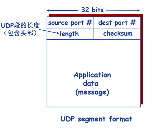
- 多路复用和多路分用,所加头部信息为源和目的端口号。
- 简单的错误校验功能,所加头部信息为检验和。
UDP存在的价值
- 不需要建立连接,其产生的延迟是非常短的。不需要进行三次握手。
- 关于发送什么数据以及何时发送的应用层控制更为精细。
- 实现简单,无需维护连接状态。不需要如同TCP一样维护接受发送缓存,序号,拥塞窗口等参数。
- 头部开销少,UDP头部8字节,TCP20字节。
传输信息格式
应用场合
- 常用于流媒体应用,由于该类应用容忍丢失,而且速率敏感
- DNS
- SNMP
UDP也可以依靠上层应用设置可靠数据传输,不过对于应用开发的难度较大
- 在应用层增加可靠性机制
- 应用特定的错误恢复机制
可靠数据传输原理
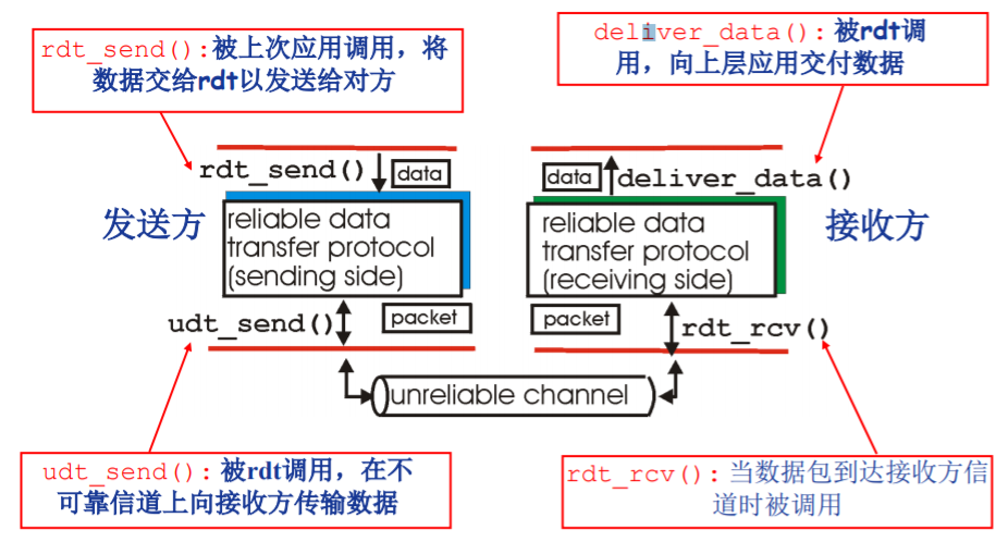
所要解决的问题
- 在不可靠的下层传输协议支持下,构建一个可靠的数据传输方式
其概念图可以表示如下:
可靠的概念
- 不错,所传输的数据包不可以发送某一位的错误
- 不丢,不可以发生数据包的丢失,而不知晓
- 不乱,不可以发生重复数据包的接受,而不知晓
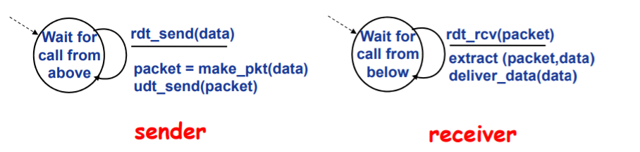
Rdt1.0:可靠信道上的可靠数据传输
特点
-
底层信道完全可靠,即:不会发生错误,不会丢弃分组
-
不需要采用任何机制
FSM
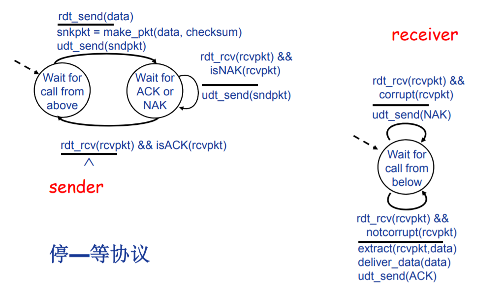
Rdt2.0: 产生位错误的信道
特点
- 底层信道可能发生位错误,且仅仅可能发生位错误
- 基于ACK(positive acknowledgment)与NCK(negative acknowledgment)的自动重传请求(Automatic Repeat reQuest, ARQ)机制。
自动重传请求(Automatic Repeat reQuest, ARQ)机制
-
差错检测:可以使用校验和机制进行校验,使得接收方可以判断数据出现问题
-
ACK和NAK机制。发送方会收到接收方的反馈控制消息(ACK/NAK),对数据进行处理
-
确认消息(Acknowledgements, ACK): 接收方显式地告知发送方分组已正确接收
-
确认错误消息(Unacknowledgements, NAK):接收方显式地告知发送方分组有错误
-
重传机制。如果发送方收到NAK,将会重新传输相应的数据包
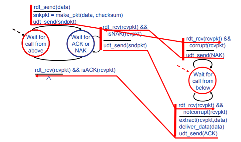
FSM
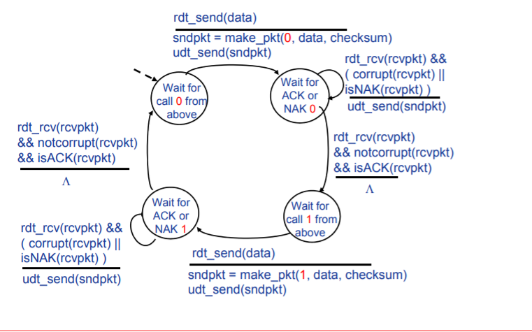
Rdt2.1:NCK和ACK的损坏处理
所要解决的问题
在Rdt2.0协议中,可能会发生ACK和NAK详细发生错误和被破坏,需要对这种情况进行处理,可以采用以下办法:
-
为ACK/NAK增加校验和,检错并纠错,实际实现难度较大,一般难以实现百分之百的纠错。
-
如同对于原数据的处理一样,增加额外的控制消息,实际上会陷入无穷无尽地迭代,如果这些控制消息再出错怎么办,这实际上没有解决问题。
改进:ACK或NCK的出错机制
- ACK和NCK添加校验位,使得发送方可以判断ACK和NCK是否出错
- 当ACK或NCK出错时,重传分组
- 为分组添加序号。目的:保证接收方可以判断所到达的分组是新分组还是因ACK损坏而重新发送的分组
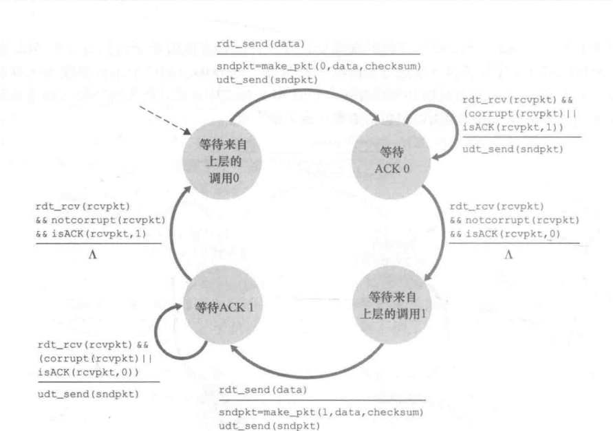
FSM
发送方
接收方
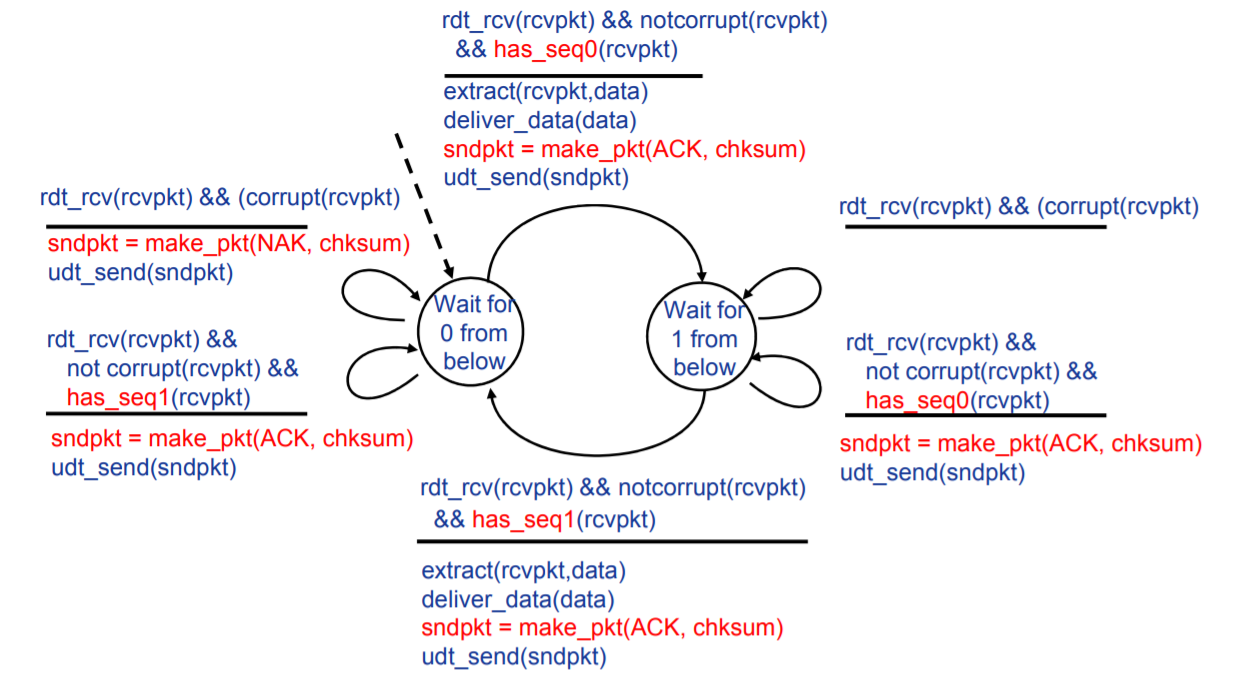
在接受方:当处于接受序号0分组的状态接收到序号1分组时,接收方所作出的处理是,发送ACK控制信息。
说明此时,发送方处于上一个分组的发送等待状态,即,其收到的ACK消息发生错误,当接受端发送ACK消息后,其会进行下一个数据包的发送。
如果发送NCK或者不做任何处理,发送方将认为上一个分组接受端未接受到或者接受的分组错误,其要么等待,要么继续发送上一个分组,这都是我们不希望看到的。
对于Rdt2.1来讲,序号0/1进行标识分组就完全够用。
因为发送端必须确认接受端接受到上一个分组,而后会发送下一个分组。所以,对于接受端而言,只可能产生两个分组的混淆或者重复。
可以说,这是由于Rdt2.0的stop and wait特性决定的。
Rdt2.2:无NAK消息协议
改进
为减少程序复杂性,取消NAK消息的发送,具体实现为:
- 为ACK添加被确认分组的序号,接收方通过ACK告知最后一个被正确接收的分组
- 发送方收到重复ACK之后,采取与收到NAK消息相同的动作,即:重传当前分组
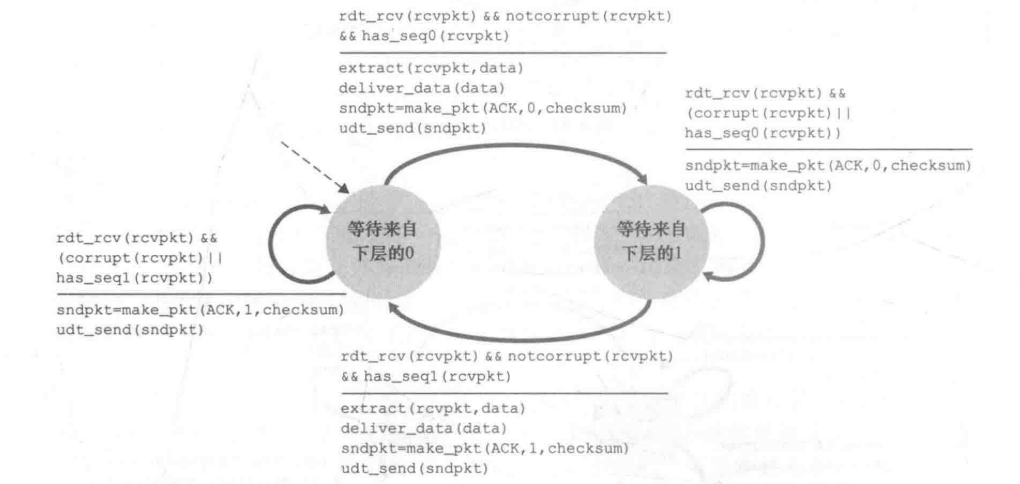
FSM
其实,在发送端的改变并不是很大,而是在接受端将两个事件进行了整合。
Rdt3.0:产生位错误和丢失分组的信道
问题
- 底层信道可能产生位错误,而且可能会丢失分组
方法
- 采用定时器机制。设置“等待合理时间”,如果没有收到ACK,将会重新发送分组。目的:解决可能丢失的分组以及确认分组的ACK。
- 采用序号机制。目的:解决可能出现的冗余数据分组问题。(序号机制其实在rdt2.1中就已经使用,都是为了解决可能出现的冗余分组问题,但是rdt2.1和rdt3.0冗余分组产生的原因并不相同)
FSM
发送方
可以观察到的是:对于重传分组,rdt3.0将ACK损坏和ACK冗余确认的情况都完全整合到超时中,即只有超时会重传分组。
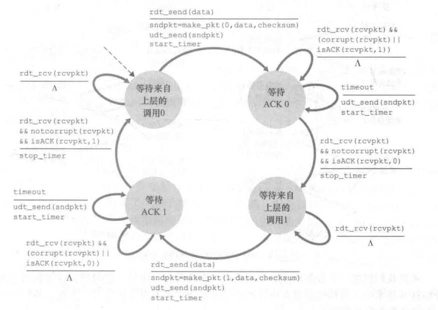
接收方
接收方完全等同于rdt2.2,也就是说,rdt3.0并没有对接受方做出任何改变。
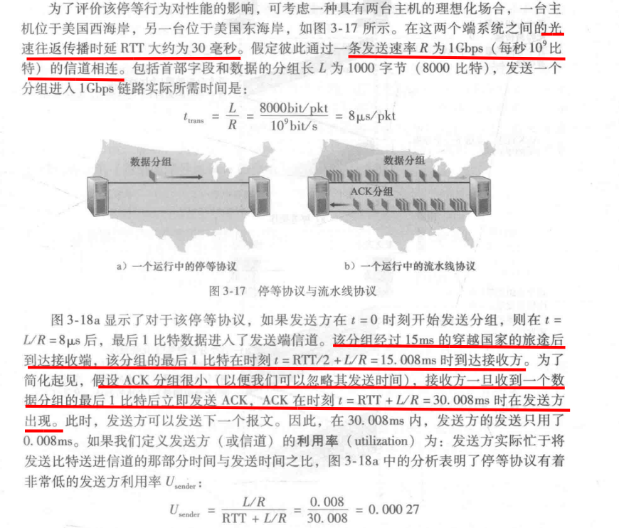
rdt3.0性能分析
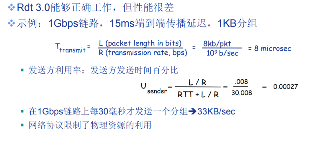
值得注意的是:Usender公式中的RTT,是指数据的传播延迟+ACK的传播延迟,二者都是一侧通信。
这样的低效率的原因就是:stop and wait类型,在发送端无法确认上一个分组被正确接受时,不会发送下一个分组。
流水线机制
所要解决的问题
- 虽然Rdt3.0可以有效的数据的不错,不丢,但是其效率太低了
所采用的方法
-
不以停等方式运行,允许发送方发送多个分组而无须等待确认
-
采用流水线机制的思想,即,可以同时发送n个包。如下图,如果同时发送n个包,那么其效率就大约提升了n倍。
-
更大的序列号范围,以供接受端可以识别分组。
-
缓存。接收方必须缓存已发送但未确认的分组。接受方可以选择缓存也可以不缓存,这取决于协议的类型。
-
对于可能出现的问题,将可以采用两种办法:回退N步(Go-Back-N, GBN)和选择重传(Selective Repeat, SR)
滑动窗口协议
- 基序号(base):最早未确认分组的序号
- 下一个序号(nextqnum):最小未使用的序号
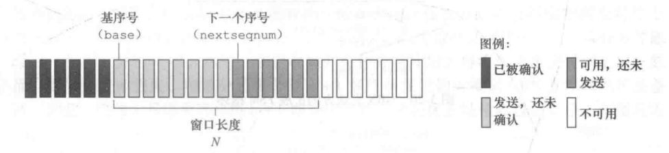
-
窗口:允许使用的序列号范围 ,窗口尺寸为N:最多有N个等待确认的消息
-
滑动窗口:随着协议的运行,窗口在序列号空间内向前滑动
GNB协议(Go-Back-N)FSM
发送端有穷自动机说明
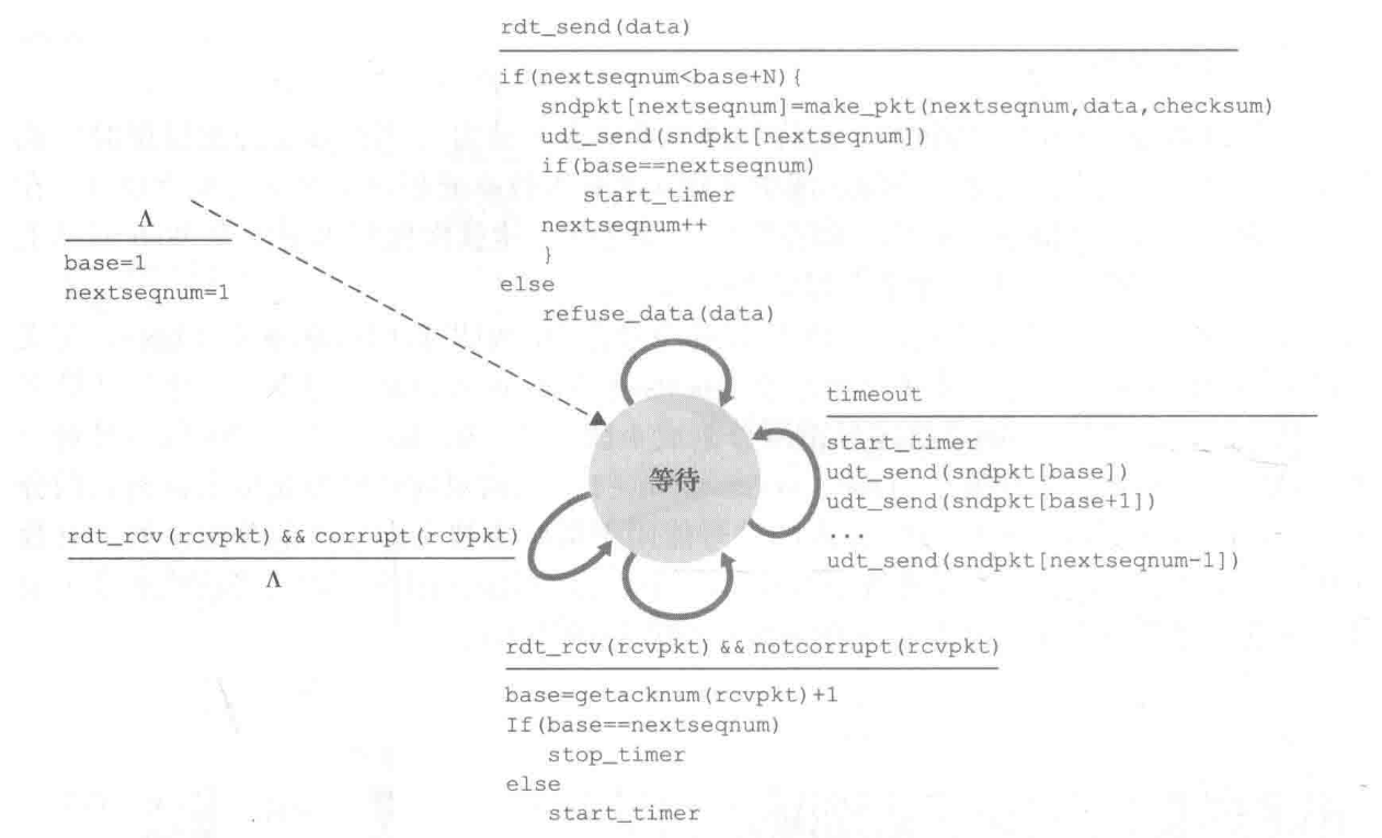
- ∧所标定的动作为初始动作,最开始直接将base = 1,nextsequm = 1。
《事件1:上层要求》
- 上层的调用。如果发送窗口未满,则发送该分组,否则拒绝该分组。
《事件2:超时》
-
超时。当发生超时事件,发送方将重传发送窗口内的全部分组,即:已发送未确认分组。
-
采用一个计时器。可以认为:计时器所记录的分组永远是窗口中第一个元素的发送时间,当然可能不完全等于,可以认为为它标定了一个上界。
《事件3:接收到有效的ACK》
-
ACK累积确认。当发送方收到序号为n的分组的确认ACK,表明接收方已正确收到序号为n以前且包含n在内的所有分组。
-
窗口移动。每收到一个确认分组序号大于base的ACK,都将base置为该ACK序号。
接受端有穷自动机说明
- 接收方丢弃乱序到达的分组。接收方没有缓存,只会接受当前状态所需要的分组。
- 当接收到乱序分组,会重复发送当前已确认的ACK。
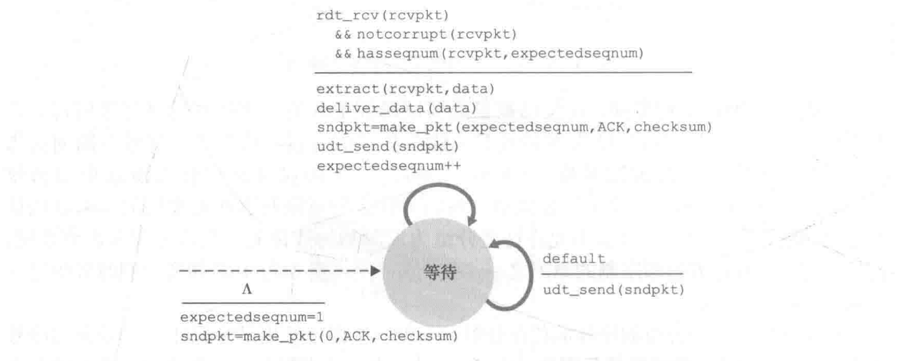
SR协议(Selective Repeat)FSM
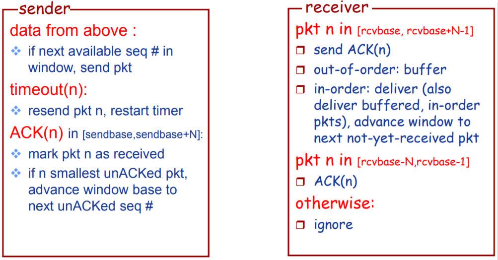
发送方有穷自动机说明
《事件1:上层调用》
- 上层的调用。如果发送窗口未满,则发送该分组,否则拒绝该分组。
《事件2:超时》
- 超时事件。当某个计时器发生超时,发送方仅仅重传该计时器所记录的分组。
- 采用多个计时器。为发送的每一个分组进行计时。
《事件3:接收到有效ACK》
- 窗口移动。当base的ACK收到会移动窗口至下一位。
- ACK单独确认。某一序号的ACK只能表明接收方成功接受并确认了该分组。
接受端有穷自动机说明
- 接收方将会缓存 序号在接受窗口内的 乱序到达的分组,且发送该分组的ACK。
- 当接收到窗口之外的序号,要进行重新确认。
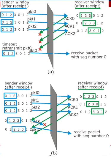
可能存在的问题
当采用SR协议时,可能会产生分组序号的误判问题,如下图,上方接受端接收到的序号为0的分组明显不同于下方接收端接收到的序号为1的分组。
该问题产生的根本原因是,所采取的分组编号数目太小,一般而言,如果保证: 发送端滑动窗口的序号数目 + 接受端滑动窗口的序号数目 <= 分组编号数目(注意:这里的等于是可以成立的),那么此种情况就会不会出现。
TCP协议
因特网的网络层服务(IP服务)是不可靠的。IP不保证数据报的交付,不保证数据报的按序交付,不保证数据包中数据的完整性。(emm,我想问一句,它保证什么?)
TCP是建立于IP上的一种可靠数据传输服务(reliable data transfer service)。
可靠也就是说,其保证:进程从接收缓存中读出的数据流是无损坏的,无间隙的,非冗余的按序的数据流,即该字节流与链接的另一方端系统发送出的字节流完全相同。
Ps:
TCP协议并不是完全的GBN协议,因为接受端存在缓存,会接受乱序的数组。但更不是SR协议。可以认为是一个接受端存在缓存的GBN协议。
当然,官方的叫法是选择确认(selective acknowledgment)。
Characterisitic
- 面向连接的,connection-oriented
- before one application process can begin to send data to another, the two processes must first “handshake” with each other—that is, they must send some preliminary(预备,测试) segments to each other to establish the parameters of the ensuing data transfer
- the “connection” is a logical one, with common state residing only in the TCPs in the two communicating end systems.
- both sides of the connection will initialize many TCP state variables associated with the TCP connection.
- 全双通,full-duplex
- If there is a TCP connection between Process A on one host and Process B on another host, then application-layer data can flow from Process A to Process B at the same time as application-layer data flows from Process B to Process A.
- 点到点,point-to-point
- a single sender and a single receiver. Socalled “multicasting” (see the online supplementary materials for this text)—the transfer of data from one sender to many receivers in a single send operation—is not possible with TCP.
交互流程概览
三次握手 three-way handshake
- For now it suffices to know(应当知道) that the client first sends a special TCP segment; the server responds with a second special TCP segment; and finally the client responds again with a third special segment.
- The first two segments carry no payload(有效载荷), that is, no application-layer data; the third of these segments may carry a payload.
数据传输
-
The client process passes a stream of data through the socket (the door of the process)
-
Once the data passes through the door, the data is in the hands of TCP running in the client. TCP directs this data to the connection’s send buffer, which is one of the buffers that is set aside during the initial three-way handshake.
-
From time to time, TCP will grab chunks of data from the send buffer and pass the data to the network layer.
Interestingly, the TCP specification [RFC 793] is very laid back about specifying when TCP should actually send buffered data, stating that TCP should “send that data in segments at its own convenience.”
- TCP pairs each chunk of client data with a TCP header, thereby forming TCP segments.The segments are passed down to the network layer, where they are separately encapsulated within network-layer IP datagrams. The IP datagrams are then sent into the network.
- When TCP receives a segment at the other end, the segment’s data is placed in the TCP connection’s receive buffer The application reads the stream of data from this buffer.
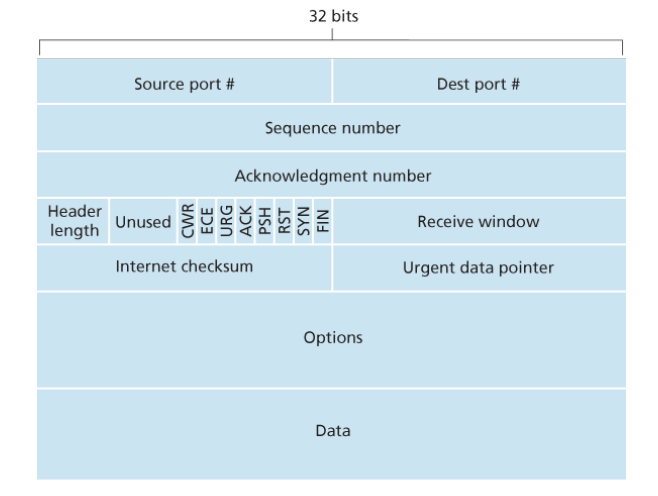
Segment Structure
-
source and destination port numbers, which are used for multiplexing/demultiplexing data from/to upper-layer applications.
-
The 32-bit sequence number field and the 32-bit acknowledgment number field
-
The 4-bit header length field specifies the length of the TCP header in 32-bit words.(32bit为单位) The TCP header can be of variable length due to the TCP options field. (Typically, the options field is empty, so that the length of the typical TCP header is 20 bytes.)
-
The optional and variable-length options field is used when a sender and receiver negotiate(协商) the maximum segment size (MSS) or as a window scaling(缩放) factor for use in high-speed networks. A timestamping option is also defined.
-
The flag field contains 6 bits.
- The ACK bit is used to indicate that the value carried in the acknowledgment field is valid; that is, the segment contains an acknowledgment for a segment that has been successfully received.
- The RST, SYN, and FIN bits are used for connection setup and teardown
- The CWR and ECE bits are used in explicit congestion notification(显式拥塞通知)
- The PSH bit indicates that the receiver should pass the data to the upper layer immediately.
- the URG bit is used to indicate that there is data in this segment that the sending-side upper-layer entity has marked as “urgent.”(紧急)The location of the last byte of this urgent data is indicated by the 16-bit urgent data pointer field. TCP must inform the receiving-side upperlayer entity when urgent data exists and pass it a pointer to the end of the urgent data.
In practice, the PSH, URG, and the urgent data pointer are not used
Sequence Numbers and Acknowledgment Numbers
The sequence number for a segment is therefore the byte-stream number of the first byte in the segment.
TCP views data as an unstructured, but ordered, stream of bytes. TCP’s use of sequence numbers reflects this view in that sequence numbers are over the stream of transmitted bytes and not over the series of transmitted segments.
Eg:
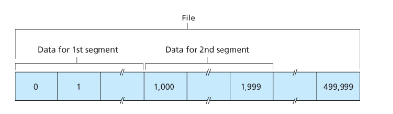
Suppose that a process in Host A wants to send a stream of data to a process in Host B over a TCP connection. The TCP in Host A will implicitly number each byte in the data stream.
Suppose that the data stream consists of a file consisting of 500,000 bytes, that the MSS is 1,000 bytes, and that the first byte of the data stream is numbered 0.
As shown in Figure followed, TCP constructs 500 segments out of the data stream. The first segment gets assigned sequence number 0, the second segment gets assigned sequence number 1,000, the third segment gets assigned sequence number 2,000, and so on. Each sequence number is inserted in the sequence number field in the header of the appropriate TCP segment.
Recall that TCP is full-duplex, so that Host A may be receiving data from Host B while it sends data to Host B (as part of the same TCP connection). Each of the segments that arrive from Host B has a sequence number for the data flowing from B to A.
The acknowledgment number that Host A puts in its segment is the sequence number of the next byte Host A is expecting from Host B.
Eg1:
Suppose that Host A has received all bytes numbered 0 through 535 from B and suppose that it is about to send a segment to Host B. Host A is waiting for byte 536 and all the subsequent bytes in Host B’s data stream. So Host A puts 536 in the acknowledgment number field of the segment it sends to B.
Eg2:
As another example, suppose that Host A has received one segment from Host B containing bytes 0 through 535 and another segment containing bytes 900 through 1,000. For some reason Host A has not yet received bytes 536 through 899. In this example, Host A is still waiting for byte 536 (and beyond) in order to re-create B’s data stream. Thus, A’s next segment to B will contain 536 in the acknowledgment number field. Because TCP only acknowledges bytes up to the first missing byte in the stream, TCP is said to provide cumulative acknowledgments.
对于Eg2中产生的无序包,TCP协议并没有做出明确规定,就如同没有规定如何发送包一样。
PS:
we assumed that the initial sequence number was zero. In truth, both sides of a TCP connection randomly choose an initial sequence number. This is done to minimize the possibility that a segment that is still present(存在) in the network from an earlier, already-terminated(终止) connection between two hosts is mistaken for a valid segment in a later connection between these same two hosts (which also happen to be using the same port numbers as the old connection)
Eg:
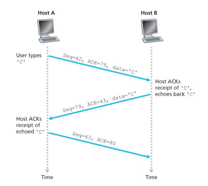
telnet. Each character typed by the user (at the client) will be sent to the remote host; the remote host will send back a copy of each character, which will be displayed on the Telnet user’s screen.
The second segment is sent from the server to the client. It serves a dual purpose. First it provides an acknowledgment of the data the server has received. The second purpose of this segment is to echo back the letter ‘C.’
the acknowledgment for client-to-server data is carried in a segment carrying server-to-client data; this acknowledgment is said to be piggybacked(被捎带) on the server-to-client data segment.
The third segment is sent from the client to the server. Its sole purpose is to acknowledge the data it has received from the server. This segment has an empty data field(the acknowledgment is not being piggybacked with any client-to-server data)
TCP连接管理
本节所要介绍的是:如果建立和拆除一条TCP连接
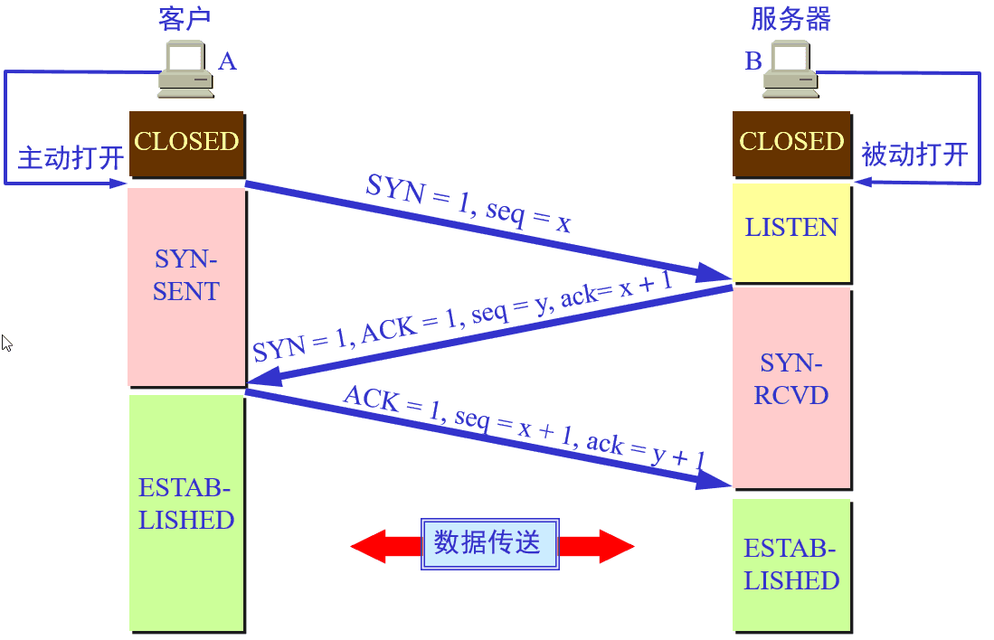
TCP连接的建立
- 处于CLOSED状态的客户端TCP首先向服务器段的TCP发送一个SYN Segement,表明其想要向该服务器端请求TCP连接,进入SYN_SENT状态。
由客户端TCP在第一握手时发送的Segment(SYN)的特征有:
- 该Segment不包含应用层数据。
- 该Segement的header中SYN标志位被置为1。
- 客户端会随机的选择一个初始序号(client_isn),并将此编号放置于该segment的sequence number字段中。
- 一旦客户端TCP发送的SYN Segment到达处于LISTEN状态的服务器(以datagram的形式),服务器会为该TCP分配TCP缓存和变量,并向该客户端TCP发送允许连接的SYN&&ACK segment,表明该服务器端同意建立TCP连接,服务器进入SYN_RCVD状态。
服务器向客户端TCP发送允许连接的SYN&&ACK Segment的特征是:
- 该Segment不包含应用层数据。
- 该Segement的header中SYN标志位被置为1。
- 该Segement的acknowledgment number field为client_isn+1。
- 服务器端会选择自己的初始序号(server_isn),并将其放置到TCP报文段header的sequence number字段中。
- 当处于SYN_SENT状态的客户端收到SYN&&ACK segment后,客户端也需要给该TCP连接分配缓存和变量。此时,客户端会向服务器发送一个Segment,表明客户端已经确认服务器端已同意建立TCP连接,客户端进入ESTACLISHED状态。此时,可以进行正常的数据传送。
此segment的特征为:
- 该Segment可以包含应用层数据。
- 该Segement的header中SYN标志位被置为0。
- 其sequence number = client_isn + 1。同时,acknowledgment number field为server_isn + 1。
- 当处于SYN_RCVD状态服务端接收到ACK后,进入ESTACLISHED状态。进行数据传送。
这样的连接机制可能会出现问题,由于在二次握手后,服务器端将会分配一部分的缓存,那么当恶意攻击者使用大量的客户端请求建立TCP连接,但是不进行第三次的握手,会造成服务器端故障。
值得注意的一点是:一般的报文段不携带数据将不消耗序号。SYN报文段虽然不携带数据, 但是也要消耗1个序列号。
前两次握手客户端和服务端都需要向对方回复 x+1 或 y+1。最后一次握手在默认不携带数据的情况下, 由于SYN 不是 1 , 是不消耗序列号的。 所以三次握手结束后, 客户端下一个发送的报文中 seq 依旧是 x+1。
TCP连接的拆除
对于TCP而言,参与一条TCP连接的两个进程中的任何一个都能终止该连接。连接结束后,主机中的“资源”(即缓存和变量)将被释放。
这里处理成为两个部分,第一个部分以状态进行阐述,第二个部分以通道开闭进行阐述,个人更倾向于第一个部分。
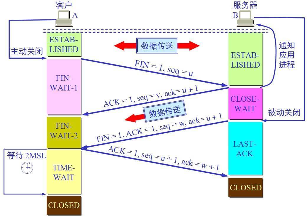
- Step 1 (FIN From Client) – Suppose that the client application decides it wants to close the connection. (Note that the server could also choose to close the connection). This causes the client send a TCP segment with the FIN bit set to 1 to server and to enter the FIN_WAIT_1 state. While in the FIN_WAIT_1 state, the client waits for a TCP segment from the server with an acknowledgment (ACK).
- Step 2 (ACK From Server) – When Server received FIN bit segment from Sender (Client), Server Immediately send acknowledgement (ACK) segment to the Sender (Client).
- Step 3 (Client waiting) – While in the FIN_WAIT_1 state, the client waits for a TCP segment from the server with an acknowledgment. When it receives this segment, the client enters the FIN_WAIT_2 state. While in the FIN_WAIT_2 state, the client waits for another segment from the server with the FIN bit set to 1.
此时,是否可以说关闭了写通道?
- Step 4 (FIN from Server) – Server sends FIN bit segment to the Sender(Client) after some time when Server send the ACK segment (because of some closing process in the Server).
- Step 5 (ACK from Client) – When Client receive FIN bit segment from the Server, the client acknowledges the server’s segment and enters the TIME_WAIT state. The TIME_WAIT state lets the client resend the final acknowledgment in case the ACK is lost.The time spent by client in the TIME_WAIT state is depend on their implementation, but their typical values are 30 seconds, 1 minute, and 2 minutes. After the wait, the connection formally closes and all resources on the client side (including port numbers and buffer data) are released.
这里是关于TCP连接拆除的另一种看法,不过,个人感觉可能存在一些问题,毕竟,TCP连接是一种逻辑连接,而且其依靠与IP协议,如果赤裸裸地将之看为直通通道,是不是有些不太合适。
首先,需要了解清楚的概念:
TCP协议的连接是全双工连接,一个TCP连接存在双向的读写通道。
简单说来是 “先关读,后关写”,一共需要四个阶段。以客户机发起关闭连接为例
- 服务器读通道关闭
- 客户机写通道关闭
- 客户机读通道关闭
- 服务器写通道关闭
具体过程(客户端与服务端相互完全对称):
第一阶段,客户机发送完数据之后,向服务器发送一个FIN数据段,序列号为i;
- 服务器收到FIN(i)后,返回确认段ACK,序列号为i+1,关闭服务器读通道;
- 客户机收到ACK(i+1)后,关闭客户机写通道;(此时,客户机仍能通过读通道读取服务器的数据,服务器仍能通过写通道写数据)
第二阶段 服务器发送完数据之后,向客户机发送一个FIN数据段,序列号为j;
- 客户机收到FIN(j)后,返回确认段ACK,序列号为j+1,关闭客户机读通道;
- 服务器收到ACK(j+1)后,关闭服务器写通道。
为什么建立连接协议是三次握手,而关闭连接却是四次握手呢?
- 为了实现可靠数据传输, TCP 协议的通信双方, 都必须维护一个序列号, 以标识发送出去的数据包中, 哪些是已经被对方收到的。 三次握手的过程即是通信双方相互告知序列号起始值, 并确认对方已经收到了序列号起始值的必经步骤,更为深层次的原因是TCP连接是双工的,需要可以进行双向通信。
- 如果只是两次握手, 至多只有连接发起方的起始序列号能被确认, 另一方选择的序列号则得不到确认。
为什么存在TIME-WAIT状态呢?
为了保证A发送的最后一个ACK报文能够到达B。这个ACK报文有可能丢失,因而使处于在LAST-ACK状态的B收不到A发送的FIN+ACK报文段的确认。
B会超时重传这个FIN+ACK报文段,A就能在2MSL(最长报文寿命)时间内收到这个重传的FIN+ACK报文段。接着A重传一次确认,重新启动2MSL计数器。最后A和B都正常进入到CLOSED状态。
如果A在TIME_WAIT状态不等一段时间而是在发送完ACK报文段后立即释放连接,那么就无法收到B重传的FIN+ACK报文段。B就无法按照正常步骤进入CLOSED状态。
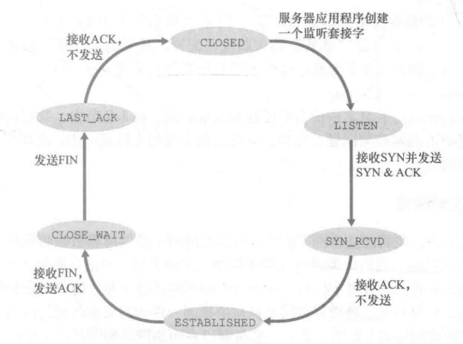
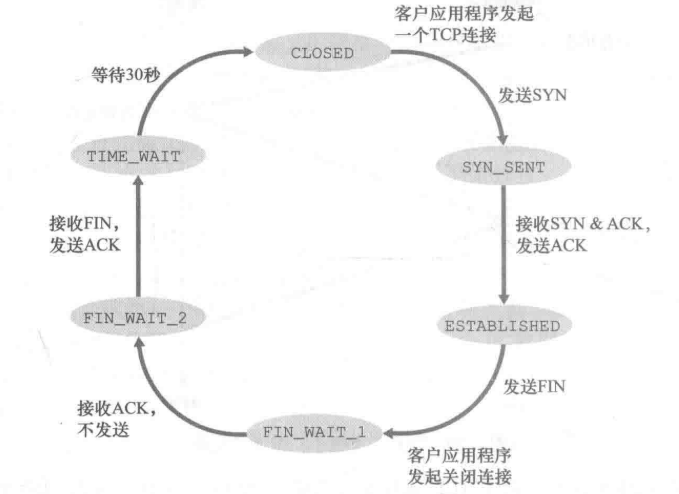
TCP连接客户端和服务端单独状态转换
上面所给均是混合的状态转换,注重于说明交互关系,这里所给为客户端和服务端单独的状态转换,可以帮助理解。
Round-Trip Time Estimation and Timeout
TCP, like our rdt protocol, uses a timeout/retransmit mechanism to recover from lost segments.
let us discuss the detail of timeout/retransmit mechanism in TCP.
SampleRTT(样本RTT)
The sample RTT, denoted SampleRTT, for a segment is the amount of time between when the segment is sent (that is, passed to IP) and when an acknowledgment for the segment is received.
- Instead of measuring a SampleRTT for every transmitted segment, most TCP implementations take only one SampleRTT measurement at a time.That is, at any point in time, the SampleRTT is being estimated for only one of the transmitted but currently unacknowledged segments, leading to a new value of SampleRTT approximately once every RTT.
- TCP never computes a SampleRTT for a segment that has been retransmitted; it only measures SampleRTT for segments that have been transmitted once.(这可能是因为不确定第一次所传送的segment是否真正丢失,因而会造称sampleRTT不准确)
EstimatedRTT(估计RTT)
the SampleRTT values will fluctuate from segment to segment due to congestion in the routers and to the varying load on the end systems.
In order to estimate a typical RTT, it is therefore natural to take some sort of average of the SampleRTT values. TCP maintains an average, called EstimatedRTT, of the SampleRTT values.
Upon obtaining a new SampleRTT, TCP updates EstimatedRTT according to the following formula:
The formula above is written in the form of a programming-language statement—the new value of EstimatedRTT is a weighted combination of the previous value of EstimatedRTT and the new value for SampleRTT. The recommended value of α is α = 0.125 (that is, 1/8)
也就是说,这个迭代公式既保留了历史EstimatedRTT的特征,又融合了现在SampleRTT的特征。
DevRTT(偏差RTT)
In addition to having an estimate of the RTT, it is also valuable to have a measure of the variability(变化) of the RTT.
DevRTT, as an estimate of how much SampleRTT typically deviates from EstimatedRTT:
The recommended value of β is 0.25.
TCP’s timeout interval(超时间隔)
Clearly, the interval should be greater than or equal to EstimatedRTT, or unnecessary retransmissions would be sent. But the timeout interval should not be too much larger than EstimatedRTT; otherwise, when a segment is lost, TCP would not quickly retransmit the segment, leading to large data transfer delays.
It is therefore desirable to set the timeout equal to the EstimatedRTT plus some margin. The margin should be large when there is a lot of fluctuation in the SampleRTT values; it should be small when there is little fluctuation. The value of DevRTT should thus come into play here.
All of these considerations are taken into account in TCP’s method for determining the retransmission timeout interval:
An initial TimeoutInterval value of 1 second is recommended.
Also, when a timeout occurs, the value of TimeoutInterval is doubled to avoid a premature timeout occurring for a subsequent segment that will soon be acknowledged.
However, as soon as a segment is received and EstimatedRTT is updated, the TimeoutInterval is again computed using the formula above.
TCP初步描述
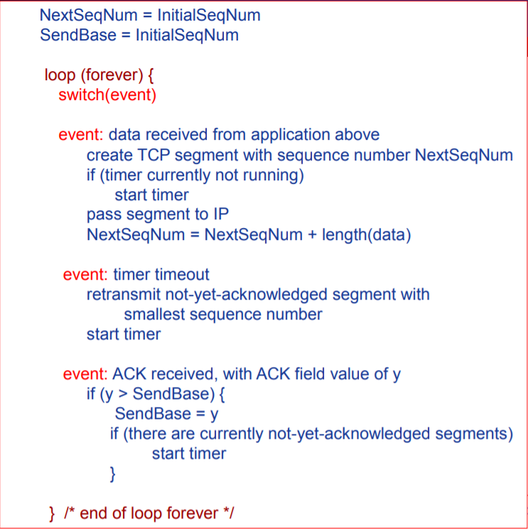
TCP发送方的初步机制描述
《事件1:上层调用》
- 上层的调用。如果发送窗口未满,则发送该分组,否则拒绝该分组。
《事件2:超时》
- 当发生超时事件,仅仅重传窗口中序号最小的分组。
- 采用单一计时器。只记录窗口中序号最小的分组发送时间情况。
- 对于timer timeout,这里需要使用前一节中所讲的timeout interval进行计算。
《接收到正确ACK》
- ACK累积确认。当发送方收到序号为n的分组的确认ACK,表明接收方已正确收到序号为n以前且包含n在内的所有分组。
- 窗口移动。每收到一个确认分组序号大于base的ACK,都将base置为该ACK序号。
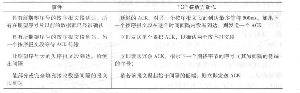
TCP接受端方的初步机制描述
- ACK累计确认机制。
超时timeout interval加倍机制
这是对于计时器所做的一个修改,保证重传的时间间隔足够长,以不造成没有必要的重传。
- 当计时器超时,重传某个segment时,此时的timeout interval为之前timeout interval的2倍
- 当发送端处于其他两种情况(收到上层数据以及收到ACK)时,timeout interval由最*的EstimatedRTT以及DevRTT推算得到。
Ps:
此机制也可以看作是一个拥塞控制机制。因为计时器超时可能由于网络拥塞导致,即太多的分组到达源与目的地之间路径上的一台或多台路由器的排队队列中,造成分组丢失或者长时间的排队延迟。
如果持续重传分组,会使得拥塞更加严重,TCP以逐渐2倍的形式,有效的解决了这个问题。
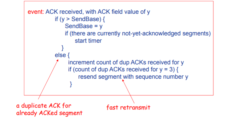
快速重传机制
超时触发重传机制很可能会由于超时周期相对较长,延缓了发送方重新发送segment的时间,增加了端到端的延迟。
- 冗余ACK:再次确认某个segment的ACK,而发送方已经收到了对于该segment的确认。
- 冗余ACK的产生一方面由于报文段的缺失,一方面由于报文段的乱序到达。
- 在TCP中规定,如果TCP发送方接收到对于相同segment的3个冗余ACK,将认为已被期待传输3次的segment已经丢失,这就是快速重传。
流量控制机制
流量控制
当接收方的缓存不断缓存发送方发送的数据,而上层应用从接收方的缓存中读取数据的速度过慢,而发送方发送数据的速度相对过快,可能会造成淹没接收方缓存区的问题。
流量控制实际上就是一个速度匹配服务,匹配TCP的传输速率以及接收方应用程序的读取速率。
TCP要求发送方以及接收方各自维护一个变量:接受窗口(receive window),该变量用于指明接受方还有多少可用的缓冲空间。
接收方会将其接受窗口放入其发向发送端的Segment的Receive windows字段中,告知发送方当前接受窗口的大小。
接受窗口定义如下:
其中,
- RecBuffer:当前TCP连接接收方被分配的接受缓存的容量
- LastByteRead:接受方的上层应用从缓冲中读取的数据流的最后一个字节的编号
- LastByteRcvd:从网络中到达的并且已放入接受方缓存的数据流的最后一个字节的编号。
存在的细节问题
当RcvWindow = 0时,如果不允许发送方发送Segment,会形成死锁,发送方将不能发送数据。
为此,TCP中规定,当接收方的接受窗口为0时,发送方将可以继续发送只有一个字节数据的报文段,这些报文段会被接收方确认,并返回携带RcvWindow信息的ACK。
UDP并不会提供流量控制,一旦进程读取报文段的速度不够快,缓存将溢出,丢失报文段。
拥塞控制原理
网络拥塞概论
网络拥塞:太多发送主机发送数据太快 ,以至于连接这些主机的网络无法有效地传输这些数据。
网络拥塞另一种更为形式化的描述是:
网络拥塞现象是指到达通信子网中某一部分的分组数量过多,使得该部分网络来不及处理,以致引起这部分乃至整个网络性能下降的现象,严重时甚至会导致网络通信业务陷入停顿,即出现死锁现象。
表现为:
- 分组丢失(路由器缓存溢出)
- 分组传输延迟过大(在路由器缓存中排队)
拥塞控制与可靠传输原理中都对分组丢失做出了处理,那么,它们有什么区别呢?
可以这样理解:可靠数据传输中的分组丢失处理是一个个体-个体的处理,即:仅仅考虑端到端。而拥塞控制中的分组丢失处理是一个社会性的问题。
分组丢失问题的原因大都是:由于网络中路由器缓存的溢出。因而可以理解为:可靠数据传输中的分组丢失仅仅做出了表面的处理,而拥塞控制中的分组丢失处理是要解决分组丢失的原因问题。这可以说与上面的描述在某种程度上是一致的。
拥塞控制和流量控制的区别:
二者的表现在某种程度上基本一致。
- 出现问题的地点之间由较大的区别,其中拥塞控制为传输网络中的 路由器,而流量控制为接受端。
- 由于地点不同,原因自然也不同了。拥塞控制是路由器发送和接受的带宽的不匹配,而流量控制是TCP的传输速率与接受端上层应用的读取速率之间的区别。
拥塞会降低吞吐率以及增大延迟
-
当分组的到达速率接*链路容量时,分组会经历巨大的排队延迟。
-
发送方必须执行重传以补偿因为路由器缓存溢出而丢弃的分组。
-
发送方在遇到大时延所进行的不必要的重传,会引起路由器利用其链路带宽进行不必要的分组副本的转发。
-
当分组被drop时,任何用于该分组的“上游”传输能力全都被浪费掉。
拥塞控制方法分类
在最为宽泛的级别上,我们可以根据网络层是否为运输层拥塞控制提供显式帮助,进行总体的拥塞控制方法的区分。
端到端的拥塞控制
- 网络层没有为运输层拥塞控制提供显式支持。
- 即使网络中存在拥塞,端系统也必须通过对网络行为的观察(如分组丢失和时延)来推断之。
网络辅助的拥塞控制
- 网络层会向发送方提供关于网络中拥塞状态的显式信息。
TCP拥塞控制
TCP必须使用端到端拥塞控制而不是网络辅助的拥塞控制,因为IP层不会向端系统提供显式的网络拥塞反馈。
拥塞窗口
为了控制TCP的发送速率,运行在发送方的TCP同色控制机制跟踪一个额外的变量,即拥塞窗口(congestion window),表示为cwnd。
拥塞窗口congestion window与接受窗口receive windows(流量控制中使用的变量)共同控制发送窗口send windows的大小:即满足以下关系:
拥塞窗口所要解决的问题是:TCP发送方如何限制它向连接发送流量的速率。
为什么拥塞窗口可以控制发送速率?
拥塞窗口的大小可以控制发送窗口的大小,发送窗口的大小将限制发送方未被确认的数据量,因而间接限制了发送方的发送速率。
从一个极为简化的例子可以看出这一点:假定存在一个丢包和发送时延据可以忽略不计的连接,因此可以认为:在每个RTT的起始点,发送方将会被允许发送sendwindows个字节的数据,那么发送速率大概为:sendwindows/RTT 字节/秒。
TCP判断拥塞出现事件
当出现报文段丢失现象(即:超时事件或者3个冗余ACK事件),被认为网络拥塞出现,此时应当降低TCP发送方的速率。
合理调整发送速率机制
加性增-乘性减AIMS
- Additive Increase:未发生丢失现象时,以线性速度增加发送速率,每个RTT只将拥塞窗口的值增加一个MSS。
一种通用的实现方法如下(在下面的状态转移也可以看到):
TCP发送方无论何时收到一个新的确认,就将拥塞窗口增加一个MSS(MSS/cwnd)字节。
Eg:MSS = 1460个字节,拥塞窗口为14600字节,那么一个RTT可以发送10个报文段,每个确认ACK的到达将增加1/10 MSS,那么是10个报文段全部确认后,拥塞窗口将增加一个MSS。
- Multiplicative:发生丢失现象时,快速降低发送速率,将拥塞窗口减半。
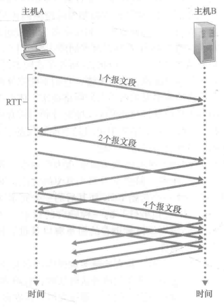
慢启动
有趣的一点是:“慢”指明:开始以很慢的速度发送数据。而会以很快的加速进行速度的提升。
- 一般来讲,在慢启动阶段,拥塞窗口的值以一个MSS开始,并且每当传输的报文段首次被确认就增加一个MSS。
- 此时的增长速率是呈指数增长的。可以参见下图:
-
TCP拥塞控制算法(TCP congestion control algorithm)
TCP拥塞控制算法可以说就是将上面的机制进行整合的处理
其定义了一个变量为Threshold(拥塞阈值),其将上面的两种的进制进行结合。
- 总体而言,起初,发送方以慢启动机制开始发送数据,当拥塞窗口增长到所设定的Threshold时,进入加性增-乘性减状态(后面将称为拥塞避免状态)进行增长。
- 当发生超时事件时,拥塞窗口将减小到1MSS,同时Threshold为超时事件发生前拥塞窗口大小的一半。此时拥塞窗口以慢启动状态进行增长。
- 当收到3个冗余ACK时,拥塞窗口 = 原拥塞窗口 / 2 + 3,同时Threshold为超时事件发生前拥塞窗口大小的一半。此时拥塞窗口以拥塞避免状态进行增长。
另一种论述
- When CongWin is below Threshold, sender in slow-start phase, window grows exponentially.
- When CongWin is above Threshold, sender is in congestion-avoidance phase, window grows linearly.
- When a triple duplicate ACK occurs, Threshold set to CongWin/2 and CongWin set to original CongWin / 2 + 3.
- When timeout occurs, Threshold set to CongWin/2 and CongWin is set to 1 MSS.
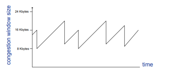
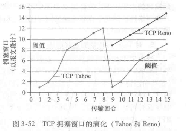
Eg:
在第8-9RTT时,发送端收到3个冗余RTT。
- TCP Reno采用超时事件与3个冗余ACK事件分别处理机制,正如上面的处理。
- TCP Tahoe将超时事件与3个冗余ACK事件看作同一事件,都将拥塞窗口降为1.
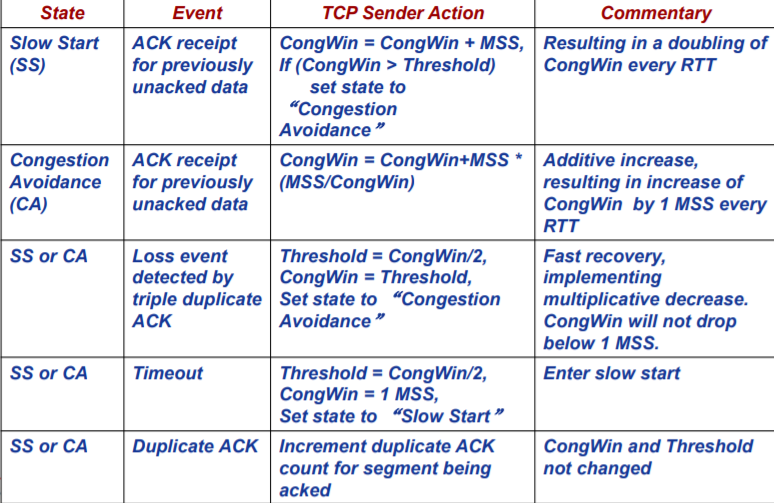
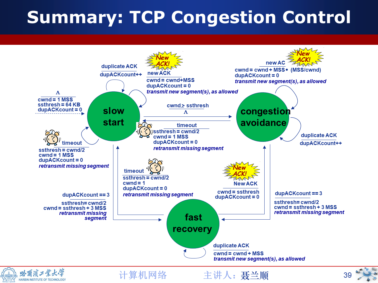
状态转移图&&状态转移表
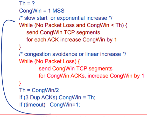
代码实现
此为旧版本,应当将倒数第二行修改为:CongWin = Th + 3。
TCP&&UDP公*性探究
公*性定义
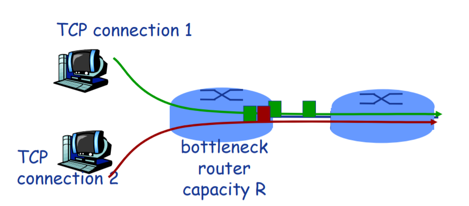
考虑多条传输连接,每条都有不同的端到端路径,但是都必须经过一段传输速率为R bps的瓶颈链路。
如果每条连接的*均传输速率都接*R/K,即每条连接都得到相同份额的链路带宽,则renewing该拥塞控制机制是公*的。
瓶颈链路:
对于每条连接,沿着该连接路径上所有其他段链路都不用色,而且与该瓶颈链路的传输容量相比,它们都有充足的传输容量。
简单而言,就是某条链路的某个特性限制了连接的传输。
TCP连接的公*性
下面将采用一个理想情况说明TCP连接的公*性。
如图,给定以下前提
- 连接1,2具有相同的MSS和RTT。(这样如果它们有相同的拥塞窗口长度,就会有相同的吞吐量)
- 没有其他TCP连接或UDP连接共享连接1,2的瓶颈链路。
- 忽略慢启动阶段,TCP连接一直处于拥塞避免(CA,AIMD)状态。
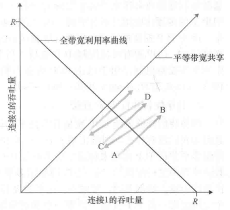
对上述曲线的分析
- 初始时刻,连接1与连接2吞吐量位于图中A点。
- 由于二者共同消耗的链路带宽量小于R,故而,这两条连接每过一个RTT都会将其拥塞窗口增加一个MSS。由于二者的MSS和RTT相同,因而增长速率相同,所以沿45°斜线进行增长。
- 当两条连接的共同小号的带宽超过R时,最终将发生分组丢失。假定连接1与2在B点时,都经历分组丢失。那么其拥塞窗口将会减半,产生C点的吞吐量。显然C点一定在B点与原点的连线之间。
- 如此往复,二者的吞吐量将不断接**等带宽共享曲线。
需要说明的是:
- 上述情况是一种极为理想化的情况。如我们所作的大量假设就可观察到。
- 一般而言,是根本无法实现如此*等的带宽份额分配。
UDP的公*性
UDP不具有拥塞控制机制,因而其连接不具有公*性。
值得一提的是:
虽然我们使用拥塞控制强迫TCP具有公*给行为。但是,由于无法禁止应用使用多个并行TCP连接,因而TCP公*性问题仍然得不到解决。
Eg:
链路速率为R,已有9个 连接
- 新来的应用请求1个TCP,获得 R/10的速率
- 新来的应用请求11个TCP,获得 R/2的速率