Verilog Circuits-Combination Logic-Basic Gate
Problem 43:Wire

实现上图电路。
module top_module (
    input in,
    output out);
    assign out=in;

endmodule
Problem 44:GND
实现如下电路

module top_module (
    output out);
assign out=1'b0;
endmodule
Problem 45:NOR
实现如下电路(或非门)

module top_module (
    input in1,
    input in2,
    output out);

    assign out = ~(in1 | in2);

endmodule
Problem 46:Another gate
实现如下电路

module top_module (
    input in1,
    input in2,
    output out);
assign out=~in2&in1;
endmodule
Problem 47:Two gates
实现如下 电路:

module top_module (
    input in1,
    input in2,
    input in3,
    output out);
wire temp;
    always @(*)
        begin
            temp=~(in2^in1);
            out=temp^in3;
        end

endmodule
Problem 48:More logic gates
用两输入,7 个输出的组合实现如下功能:
- out_and: a and b
- out_or: a or b
- out_xor: a xor b
- out_nand: a nand b
- out_nor: a nor b
- out_xnor: a xnor b
- out_anotb: a and-not b
module top_module(
    input a, b,
    output out_and,
    output out_or,
    output out_xor,
    output out_nand,
    output out_nor,
    output out_xnor,
    output out_anotb
);
    always @(*)
        begin
            out_and=a&b;
            out_or=a|b;
            out_xor=a^b;
            out_nand=~(a&b);
            out_nor=~(a|b);
            out_xnor=~(a^b);
            out_anotb=a&(~b);//不懂anotb是什么意思,抄的答案
        end
endmodule
Problem 49:7420 chip
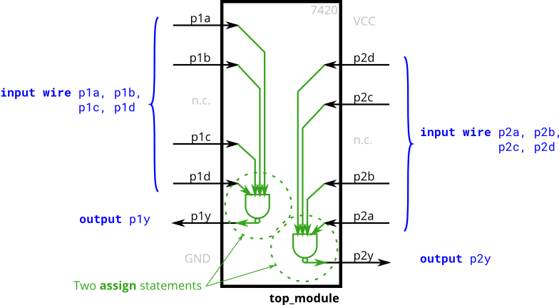
7420 芯片是具有两组 4 输入的与非门芯片,要求实现具有 8 输入,2 输出的 7420 芯片功能的电路
module top_module (
    input p1a, p1b, p1c, p1d,
    output p1y,
    input p2a, p2b, p2c, p2d,
    output p2y );
    assign p1y=~(p1a&p1b&p1c&p1d);
    assign p2y=~(p2a&p2b&p2c&p2d);

endmodule
Problem 50:Truth tables 真值表
组合逻辑电路意味着:电路的输出只是其输入的函数。
这意味着对于任何给定的输入,都有可能的输出值。
真值表可以描述组合函数行为,即列出输入输出所有可能的取值。
对于 n 个布尔函数,有 \(2^n\) 个可能的输入组合,真值表每一行列出一个输入组合,因此总共有 \(2^n\) 行,同样在每行对应有每行的输出。
- 例子:三输入一输出,输出为 1 时有四个输入组合,输出为 0 时,有四个输入组合
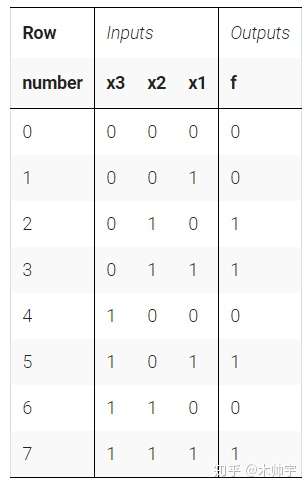
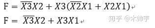
从真值表合成电路
本解析采用最小项之和的方法来构建电路图,最小项表达式为真值表中每一个对应函数值为 1 的输入变量,将上图真值表中函数值为 1 的最小项取出相加,便是函数最小项表达式。
上图最小项表达式为:

化简后如下所示:
实现具有上述真值表的组合电路
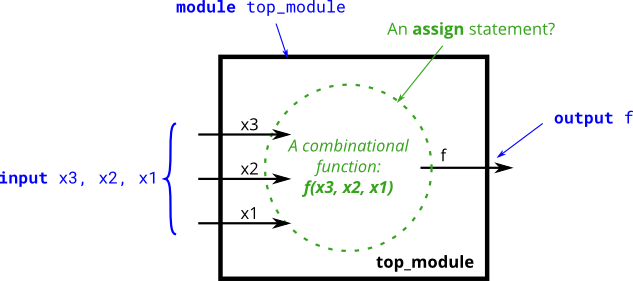
module top_module(
    input x3,
    input x2,
    input x1,  // three inputs
    output f   // one output
);

    assign f = (!x3 & x2) | (x3 & x1);

endmodule
Problem 51:Two-bit equality
创建一个两输入 input A[1:0],B[1:0],一输出 Z。
当 A 与 B 相等时,Z 输出为 1,否则为 0
//Module Declaration
module top_module ( input [1:0] A, input[1:0] B, output z);
module top_module ( input [1:0] A, input [1:0] B, output z );

    always @ (*)
        begin
            if(A == B)
                z = 1;
            else
                z = 0;      //注意需要else,不仅为符合题意,且需要消除latch(锁相器)。
        end

endmodule
- official solution
module top_module(
	input [1:0] A,
	input [1:0] B,
	output z);

	assign z = (A[1:0]==B[1:0]);	// Comparisons produce a 1 or 0 result.

	// Another option is to use a 16-entry truth table ( {A,B} is 4 bits,  with 16 combinations ).
	// There are 4 rows with a 1 result.  0000, 0101, 1010, and 1111.

endmodule
Problem 52:Simple Circuit A
创建一个电路,其功能可以实现 z = (x ^ y) & x
//Module Declaration
module top_module (input x, input y, output z);
    assign z = (x ^ y) & x;
endmodule
Problem 53:Simple Circuit B
根据仿真时序图创建电路 B。

- 根据时序图可以画出真值表,再推导出电路图
- 观察得,输出 z 为 x 与 y 的同或输出。
//Module Declaration
module top_module (input x, input y, output z);
    assign z = x ^~ y;//此处写成~x^y或~(x^y)都行,但必须知道优先级~>^
endmodule
Problem 54 Combine circuits A and B
根据子模块 Problem 53 与 54 来实现如下电路:

module top_module (input x, input y, output z);
wire z1,z2,z3,z4;
    assign z1=(x^y)&x;
    assign z2=~x^y;
    assign z3=(x^y)&x;
    assign z4=x^~y;
    assign z=(z1|z2)^(z2&z3);

endmodule
- official solution
module top_module(
	input x,
	input y,
	output z);

	wire o1, o2, o3, o4;

	A ia1 (x, y, o1);
	B ib1 (x, y, o2);
	A ia2 (x, y, o3);
	B ib2 (x, y, o4);

	assign z = (o1 | o2) ^ (o3 & o4);

	// Or you could simplify the circuit including the sub-modules:
	// assign z = x|~y;

endmodule

module A (
	input x,
	input y,
	output z);

	assign z = (x^y) & x;

endmodule

module B (
	input x,
	input y,
	output z);

	assign z = ~(x^y);

endmodule
Problem 55:Ring or vobrate
假设你正在设计一个电路来控制手机的振铃器和振动电机。当手机来电时(input ring),电路必须把震动( output motor = 1 )或响铃( output ringer = 1 )打开,但不能同时打开。当手机处于震动模式时( input vibrate = 1 ),则打开震动( output motor = 1 )。否则打开响铃。
设计思路(加粗)
硬件电路的编程与软件的变成是存在差异的,一般进行软件编程时,我们是先关注输入( if (input are )),再关注输出( then (output are ))。而在硬件编程时,我们需要转变思维方式,在确保输出是正确的情况下,再思考输入。( The (output should be ) when (inputs are)).
本题所述的要求十分适合以软件编程的命令形式来编写程序( if ring then do this ),所以我们需要试着来转变思维,用硬件的设计思路来编写该程序( assign ringer = )。
能够思考和转换两种风格是硬件设计所需的最重要技能之一。
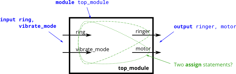
module top_module (
    input ring,
    input vibrate_mode,
    output ringer,       // Make sound
    output motor         // Vibrate
);
    assign ringer=ring&~vibrate_mode;
    assign motor=ring&vibrate_mode;

endmodule
Problem 56:Thermostat
一个冷/热恒温控制器可以同时在冬季和夏季对温度进行调节。
设计一个电路,根据需要打开和关闭加热器、空调和鼓风机风扇。(本题可参照 Problem 55 )
恒温器可以处于两种模式之一:制热(mode = 1)和制冷(mode = 0)。
在制热模式下,当温度过低时(too_cold = 1),打开加热器,但不要使用空调。
在制冷模式下,当温度过高(too_hot = 1)打开空调,但不要打开加热器。
当加热器或空调打开时,也打开风扇使空气循环。此外,即使加热器和空调关闭,用户也可以请求将风扇打开(fan_on = 1)。
module top_module (
    input too_cold,
    input too_hot,
    input mode,
    input fan_on,
    output heater,
    output aircon,
    output fan
);
assign heater=mode&too_cold;
    assign aircon=~mode&too_hot;
    assign fan=fan_on|heater|aircon;//此处我认为最好不要拿输出当输出的输入,可以写成下面这样,不过官方还是按照我的这种写法去写,迷惑
//assign fan=(mode&too_cold)|(~mode&too_hot)|fan_on;
endmodule
Problem 57:3-bit population count
设计一个电路来计算输入中 ‘ 1 ’ 个数。
//Module Declaration
module top_module
 (
     input [2:0] in,
     output [1:0] out
 );
实现:
module top_module(
    input [2:0] in,
    output [1:0] out );

       integer i;//此处不能放在always里面,试过会报错
    always @(*)
        begin
            out=2'b00;

            for(i=0;i<3;i++)
                begin
                    if(in[i]==1'b1)
                        out=out+1'b1;
                    else
                        out=out;
                end
        end

endmodule
Problem 58:Gates and vectors
给定一个 4bit 输入的电路,我们需要了解 4bit 输入数据之间的关系
- out_both : 输入的每一个 bit 均需要检测该 bit 位与其左侧(即高比特位)是否全为 ‘ 1 ’ 。 示例:
out_both[2]应检测in[2]与in[3]是否均为 ‘ 1 ’ 。因为in[3]为输入的最高位,故我们无需检测out_both[3] - out_any : 输入的每一个 bit 均需要检测该 bit 位与其右侧(即低比特位)两者其中一个为 ‘ 1 ’ 。 示例:
out_any[2]应检测in[2]与in[1]两者其中一个为 ‘ 1 ’ 。因为in[0]为输入的最低位,故我们无需检测out_any[0] - out_different : 输入的每一个 bit 均需要检测该 bit 位与其左侧(即高比特位)两者是否不同。 示例:
out_different[2]应检测in[2]与in[3]两者是否不同 。在本节中,我们将输入变成一个环,所以in[3]的左侧为in[0]。
module top_module(
    input [3:0] in,
    output [2:0] out_both,
    output [3:1] out_any,
    output [3:0] out_different );
    integer i,j,k;
    always @(*)
    	begin
            for(i=0;i<3;i++)
                out_both[i]=in[i]&in[i+1];
            for(i=3;i>0;i--)
                out_any[i]=in[i]|in[i-1];
            for(i=0;i<3;i++)
                begin
                out_different[i]=in[i]^in[i+1];
                end
            out_different[3]=in[3]^in[0];
        end

endmodule
- official solution
module top_module (
	input [3:0] in,
	output [2:0] out_both,
	output [3:1] out_any,
	output [3:0] out_different
);

	// e.g., out_any[1] = in[1] | in[0];
	// Notice how this works even for long vectors.
	assign out_any = in[3:1] | in[2:0];

	assign out_both = in[2:0] & in[3:1];

	// XOR 'in' with a vector that is 'in' rotated to the right by 1 position: {in[0], in[3:1]}
	// The rotation is accomplished by using part selects[] and the concatenation operator{}.
	assign out_different = in ^ {in[0], in[3:1]};

endmodule
Problem 59:Even longer vectors
该题与 P58 类似,仅将输入从 4bit 改为 100bit ( input [99:0] ),题目的其余要求均相同。
module top_module(
    input [99:0] in,
    output [98:0] out_both,
    output [99:1] out_any,
    output [99:0] out_different );
    assign out_both=in[98:0]&in[99:1];
    assign out_any=in[98:0]|in[99:1];
    assign out_different =in^{in[0],in[99:1]};

endmodule

 浙公网安备 33010602011771号