实验22:远程技术
六、远程技术
1、远程交换技术
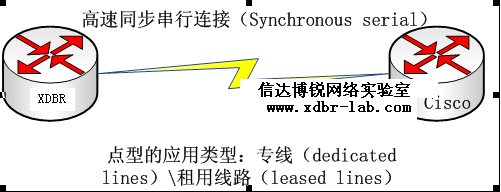
第一种类型:

优点:只属于一个公司所有,独享带宽,
缺点:价格高昂,不是所有的公司都能承受得起
第二种类型:

电路交换的最大优势就是成本低。在端到端连接之前不能传输数据。电路交换使用拨号调制解调或ISDN,用于低带宽数据传输。
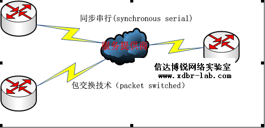
第三种类型:

包交换 :允许和其他公司共向带宽以节省资金。如果需要经常传输数据,则不要考虑这种类型,应当使用租用线路
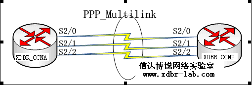
2、PPP multilink.

PPP Multilink原理:把单个PPP连接分割为两条独立的物理链路,然后以正确的顺序重新组合它们。要实现这一点的话必须在链路的两端都有一个遵从MP协议的硬件设备或软件程序。
MP是这样来执行以上功能的:
·\~源端的MP收到数据包
·\~把它们切割成碎片(可选)
·\~决定下一条可用的链路
·\~添加一个包含顺序号和其它信息的PPP Multilink包头
·\~把数据包或碎片转发到可用的链路上
·\~接受端的MP收到数据包或数据包碎片
·\~移去MP包头
·\~重新把碎片组合成完整的包
·\~转发数据包到相应的IP地址
结果是,不管这些链路在容量上有多大的差别,也不管可用带宽浮动得多么厉害,也能在可用的链路上平滑地分配流量。
MLPPP配置过程:
第1步 建立一个逻辑的MLPPP接口,使用interface multilink multilink_interface_number
第2步 给MLPPP接口分配IP地址,
第3步 把相应的PPP链路配置到相应的MLPPP group
Ppp Multilink 配置启用MLPPP
Multilink-group multilink_group_number 分配进相应的multilink group
xdbr_ccna:
xdbr_ccna(config)#interface multilink 1 \*先开启一个虚拟的接口,multilink
xdbr_ccna(config-if)#ip add 12.1.1.1 255.255.255.252 \*给虚拟接口配置地址
xdbr_ccna(config-if)#ppp multilink group 1 \*此接口加入组1中
xdbr_ccna(config-if)#int s2/0
xdbr_ccna(config-if)#encapsulation ppp \*进入物理口下不配置地址,直接封装为PPP
xdbr_ccna(config-if)#ppp multilink group 1 \*加入到虚拟接口所在的组
xdbr_ccna(config-if)#no shutdown \*记得把物理端口打开
xdbr_ccna(config-if)#int s2/1
xdbr_ccna(config-if)#encapsulation ppp \*封装为PPP.其它几个接口与第一个相同配置
xdbr_ccna(config-if)#ppp multilink group 1
xdbr_ccna(config-if)#no sh
xdbr_ccna(config-if)#int s2/2
xdbr_ccna(config-if)#encapsulation ppp
xdbr_ccna(config-if)#ppp multilink group 1
xdbr_ccna(config-if)#no sh
xdbr_ccna(config-if)#int s2/3
xdbr_ccna(config-if)#encapsulation ppp
xdbr_ccna(config-if)#ppp multilink group 1
xdbr_ccna(config-if)#no sh
xdbr_ccnp:
xdbr_ccnp(config)#interface multilink 1 \*在此台路由器上一样也要起个虚拟接口
xdbr_ccnp(config-if)#ip add 12.1.1.2 255.255.255.252 \*地址配置在虚拟接口上
xdbr_ccnp(config-if)#ppp multilink group 1 \*加入到一个组
xdbr_ccnp(config-if)#int s2/0
xdbr_ccnp(config-if)#encapsulation ppp
xdbr_ccnp(config-if)#ppp multilink group 1
xdbr_ccnp(config-if)#no sh
xdbr_ccnp(config-if)#int s2/1
xdbr_ccnp(config-if)#encapsulation ppp
xdbr_ccnp(config-if)#ppp multilink group 1
xdbr_ccnp(config-if)#no sh
xdbr_ccnp(config-if)#int s2/2
xdbr_ccnp(config-if)#encapsulation ppp
xdbr_ccnp(config-if)#ppp multilink group 1
xdbr_ccnp(config-if)#no sh
xdbr_ccnp(config-if)#int s2/3
xdbr_ccnp(config-if)#encapsulation ppp
xdbr_ccnp(config-if)#ppp multilink group 1
xdbr_ccnp(config-if)#no sh
xdbr_ccna#sh int s2/0
Serial1/0 is up, line protocol is down
Hardware is M4T
MTU 1500 bytes, BW 1544 Kbit, DLY 20000 usec,
reliability 255/255, txload 1/255, rxload 1/255
Encapsulation PPP, LCP Listen, multilink Closed
xdbr_ccnp#sh interfaces multilink 1
Multilink1 is up, line protocol is up
Hardware is multilink group interface
Internet address is 12.1.1.2/30
MTU 1500 bytes, BW 4632 Kbit, DLY 100000 usec,
reliability 255/255, txload 1/255, rxload 1/255
Encapsulation PPP, LCP Open, multilink Open
xdbr_ccnp#sh ppp multilink
Multilink1, bundle name is xdbr_ccna
Bundle up for 00:03:12, 1/255 load
Receive buffer limit 48768 bytes, frag timeout 1000 ms
0/0 fragments/bytes in reassembly list
0 lost fragments, 0 reordered
0/0 discarded fragments/bytes, 0 lost received
0xC received sequence, 0xA sent sequence
Member links: 4 active, 0 inactive (max not set, min not set)
Se2/0, since 00:03:12
Se2/1, since 00:02:54
Se2/2, since 00:02:46
Se2/3, since 00:02:36
如果其中的一个物理口down 了,则multilink接口的带宽也会跟着下降
xdbr_ccnp#debug ppp multilink fragments \*调试,查看MLP帧的情况
Multilink fragments debugging is on
xdbr_ccnp#
*Mar 1 00:18:50.339: Se2/0 MLP: I frag 8000000C size 90 encsize 4
*Mar 1 00:18:50.339: Se2/1 MLP: I frag 0000000D size 90 encsize 4
*Mar 1 00:18:50.339: Se2/2 MLP: I frag 0000000E size 90 encsize 4
*Mar 1 00:18:50.339: Se2/3 MLP: I frag 4000000F size 94 encsize 4
xdbr_ccnp#
*Mar 1 00:18:58.615: Se2/0 MLP: I frag 80000010 size 58 encsize 4
*Mar 1 00:18:58.615: Se2/1 MLP: I frag 40000011 size 60 encsize 4
*Mar 1 00:18:58.615: Se2/2 MLP: O frag 8000000E size 58 encsize 4
*Mar 1 00:18:58.615: Se2/3 MLP: O frag 4000000F size 60 encsize 4
*Mar 1 00:18:58.655: Se2/2 MLP: I frag 80000012 size 58 encsize 4
*Mar 1 00:18:58.655: Se2/3 MLP: I frag 40000013 size 60 encsize 4
*Mar 1 00:18:58.655: Se2/0 MLP: O frag 80000010 size 58 encsize 4
*Mar 1 00:18:58.655: Se2/1 MLP: O frag 40000011 size 60 encsize 4
*Mar 1 00:18:58.707: Se2/0 MLP: I frag 80000014 size 58 encsize 4
*Mar 1 00:18:58.707: Se2/1 MLP: I frag 40000015 size 60 encsize 4
现在做如下测试,让xdbr_ccna去ping xdbr_ccnp,这时间把xdbr_ccnp 上的任意一个接口给断开
xdbr_ccna#ping 12.1.1.2 repeat 10000
Type escape sequence to abort.
Sending 10000, 100-byte ICMP Echos to 12.1.1.2, timeout is 2 seconds:
!!!!!!!!!!!!!!!!!!!!!!!!!!!!!!!!!!!!!!!!!!!!!!!!!!!!!!!!!!!!!!!!!!!!!!
!!!!!!!!!!!!!!!!!!!!!!!!!!!!!!!!!!!!!!!!!!!!!!!!!!!!!!!!!!!!!!!!!!!!!!
!!!!!!!!!!!!!!!!!!!!!!!!!!!!!!!!!!!!!!!!!!!!!!!!!!!!!!!!!!!!!!!!!!!!!!
!!!.!....!..!..!..!..!..!..!..!..!..!..!..!.!!!!!!!!!!!!!!!!!!!!!!
可以发现,ping走丢几个,走一个,一分钟左右恢复正常,绑定的物理口越多,丢包越少
xdbr_ccnp(config)#int s2/0
xdbr_ccnp(config-if)#sh \*关掉s2/0看到上面的效果
3、PPP认证
实验目的:测试WAN连接之间的接口认证情况
设备需求:2500或2600等系列路由器二台
实验过程:

A:PAP认证:
口令认证协议:(Password Authentication Protocol,PAP),在认证协议中安全性比CHAP(Challenge Authentication Protocol,问答握手认证协议)低,口令是以明文发送,并且PAP只在初始链路建立时执行,在PPP链路首次建立时,远程结点向发送路由器回送路由器用户名和口令直到获得认证。(比较执着)
XDBR_CCNA:
hostname XDBR_CCNA
username XDBR2 password 0 cisco \*建立一个数据库,NP到NA做认证用
!
interface Serial1/0
ip address 12.1.1.1 255.255.255.0
encapsulation ppp \*把封装类型改为PPP,默认是HDLC
ppp authentication pap \*PPP的认证类型设置为明文密码认证协议
ppp pap sent-username XDBR1 password 0 cisco \*发送自己的用户名和密码
!
XDBR_CCNP:
hostname XDBR_CCNP
!
username XDBR1 password 0 cisco \*建立一个数据库,NA到NP做认证用
!
interface Serial1/0
ip address 12.1.1.2 255.255.255.0
encapsulation ppp \*把封装类型改为PPP,默认是HDLC
ppp authentication pap \*PPP的认证类型设置为明文密码认证协议
ppp pap sent-username XDBR2 password 0 cisco \*对方对应的是数据库里信息
XDBR_CCNP#debug ppp authentication \*调试查看PPP(PAP)的认证过程
PPP authentication debugging is on
XDBR_CCNP#
*Mar 1 00:21:21.751: Se1/0 PPP: Authorization required
*Mar 1 00:21:21.859: Se1/0 PAP: Using hostname from interface PAP
*Mar 1 00:21:21.859: Se1/0 PAP: Using password from interface PAP
*Mar 1 00:21:21.859: Se1/0 PAP: O AUTH-REQ id 3 len 13 from "XDBR_CCNP"
*Mar 1 00:21:21.859: Se1/0 PAP: I AUTH-REQ id 3 len 13 from "XDBR_CCNA"
*Mar 1 00:21:21.863: Se1/0 PAP: Authenticating peer XDBR_CCNA
*Mar 1 00:21:21.863: Se1/0 PPP: Sent PAP LOGIN Request
*Mar 1 00:21:21.867: Se1/0 PPP: Received LOGIN Response PASS
*Mar 1 00:21:21.867: Se1/0 PPP: Sent LCP AUTHOR Request
*Mar 1 00:21:21.867: Se1/0 PPP: Sent IPCP AUTHOR Request
*Mar 1 00:21:21.871: Se1/0 LCP: Received AAA AUTHOR Response PASS
XDBR_CCNP#
*Mar 1 00:21:21.871: Se1/0 IPCP: Received AAA AUTHOR Response PASS
*Mar 1 00:21:21.875: Se1/0 PAP: O AUTH-ACK id 3 len 5
*Mar 1 00:21:21.959: Se1/0 PAP: I AUTH-ACK id 3 len 5
*Mar 1 00:21:21.959: Se1/0 PPP: Sent CDPCP AUTHOR Request
*Mar 1 00:21:21.963: Se1/0 PPP: Sent IPCP AUTHOR Request
*Mar 1 00:21:21.967: Se1/0 CDPCP: Received AAA AUTHOR Response PASS
备注:上述为认证成功的情况,假如认证失败,会一直发认证请求
B:CHAP认证:
CHAP,也是在链路初始启动,但周期性链路检查。
1. 链路建立阶段结束之后,认证者向对端点发送“challenge”消息。
2. 对端点用经过单向哈希函数计算出来的值做应答。
3. 认证者根据它自己计算的哈希值来检查应答,如果值匹配,认证得到承认;否则,连接应该终止。
4. 经过一定的随机间隔,认证者发送一个新的 challenge 给端点,重复步骤 1 到 3 。
xdbr_ccna:
hostname xdbr_ccna
username xdbr_ccnp password 0 cisco \*也是建立一个数据库供认证使用
interface Serial1/0
ip address 12.1.1.1 255.255.255.0
encapsulation ppp\*这里先封装为PPP
serial restart-delay 0
ppp authentication chap \*把认证方式设置为CHAP,这里不会发用户名和密码的.
xdbr_ccnp:
hostname xdbr_ccnp
username xdbr_ccna password 0 cisco
interface Serial1/0
ip address 12.1.1.2 255.255.255.0
encapsulation ppp
serial restart-delay 0
ppp authentication chap
认证成功的情况:
*Mar 1 00:08:14.123: Se1/0 PPP: Authorization required
*Mar 1 00:08:14.183: Se1/0 CHAP: O CHALLENGE id 2 len 23 from "xdbr_ccnp"
*Mar 1 00:08:14.235: Se1/0 CHAP: I CHALLENGE id 3 len 23 from "xdbr_ccna"
*Mar 1 00:08:14.239: Se1/0 CHAP: Using hostname from unknown source
*Mar 1 00:08:14.239: Se1/0 CHAP: Using password from AAA
*Mar 1 00:08:14.239: Se1/0 CHAP: O RESPONSE id 3 len 23 from "xdbr_ccnp"
*Mar 1 00:08:14.295: Se1/0 CHAP: I RESPONSE id 2 len 23 from "xdbr_ccna"
*Mar 1 00:08:14.295: Se1/0 PPP: Sent CHAP LOGIN Request
*Mar 1 00:08:14.299: Se1/0 PPP: Received LOGIN Response PASS
*Mar 1 00:08:14.299: Se1/0 PPP: Sent LCP AUTHOR Request
xdbr_ccnp#
*Mar 1 00:08:14.303: Se1/0 PPP: Sent IPCP AUTHOR Request
*Mar 1 00:08:14.303: Se1/0 LCP: Received AAA AUTHOR Response PASS
*Mar 1 00:08:14.307: Se1/0 IPCP: Received AAA AUTHOR Response PASS
*Mar 1 00:08:14.307: Se1/0 CHAP: O SUCCESS id 2 len 4
*Mar 1 00:08:14.331: Se1/0 CHAP: I SUCCESS id 3 len 4
*Mar 1 00:08:14.331: Se1/0 PPP: Sent CDPCP AUTHOR Request
*Mar 1 00:08:14.335: Se1/0 CDPCP: Received AAA AUTHOR Response PASS
*Mar 1 00:08:14.403: Se1/0 PPP: Sent IPCP AUTHOR Request
认证失败,会一定认证下去。(比较执着)
xdbr_ccnp#debug ppp authentication
PPP authentication debugging is on
*Mar 1 00:11:27.379: Se1/0 PPP: Authorization required
*Mar 1 00:11:27.503: Se1/0 CHAP: O CHALLENGE id 4 len 23 from "xdbr_ccnp"
*Mar 1 00:11:27.551: Se1/0 CHAP: I CHALLENGE id 5 len 23 from "xdbr_ccna"
*Mar 1 00:11:27.551: Se1/0 CHAP: Unable to authenticate for peer
*Mar 1 00:11:28.379: %LINEPROTO-5-UPDOWN: Line protocol on Interface Serial1/0, changed state to down
xdbr_ccnp(config)#
*Mar 1 00:11:29.659: Se1/0 PPP: Authorization required
*Mar 1 00:11:29.723: Se1/0 CHAP: O CHALLENGE id 5 len 23 from "xdbr_ccnp"
*Mar 1 00:11:29.779: Se1/0 CHAP: I CHALLENGE id 6 len 23 from "xdbr_ccna"
*Mar 1 00:11:29.779: Se1/0 CHAP: Unable to authenticate for peer
xdbr_ccnp(config)#
*Mar 1 00:11:31.899: Se1/0 PPP: Authorization required
*Mar 1 00:11:31.967: Se1/0 CHAP: O CHALLENGE id 6 len 23 from "xdbr_ccnp"
*Mar 1 00:11:32.055: Se1/0 CHAP: I CHALLENGE id 7 len 23 from "xdbr_ccna"
*Mar 1 00:11:32.059: Se1/0 CHAP: Unable to authenticate for peer
备注:CHAP不会发用户名和密码,它所对比的是hash值
4、帧中继技术(直联_基础)
实验目的:了解帧中继的工作原理及方式
设备需求:三台2600
实验过程:

R1
!
interface Serial2/0
ip address 12.1.1.1 255.255.255.252
encapsulation frame-relay
\*R1进入s2/0接口,封装为FR,配置地址,LMI和DLCI号都可以自动学到
R2:
!
interface Serial2/0
ip address 12.1.1.2 255.255.255.252
encapsulation frame-relay
\*R2进入s2/0接口,封装为FR,配置地址,LMI和DLCI号都可以自动学到
FR
frame-relay switching \*把中间的路由器封装为FR_SW,这是配置FR的关键
!
!
interface Serial2/1
encapsulation frame-relay \*把接口封装为FR
clock rate 64000 \*配置时钟,不配置不通,并且只能在DCE端配置
frame-relay lmi-type cisco \*定义LMI的类型,有三种,cisco,ansi,q933a,两边必须一致
frame-relay intf-type dce \*定义些设备为DCE设备
frame-relay route 102 interface Serial2/2 201 \*设置FR的路由,从102进,s2/2出,对方为201
!
interface Serial2/2
encapsulation frame-relay
clock rate 64000
frame-relay lmi-type cisco
frame-relay intf-type dce
frame-relay route 201 interface Serial2/1 102
备注:DLCI为R1和R2的标记,并不是指帧中继交换的接口
查看帧中继路由:
FR#show frame-relay route
Input Intf Input Dlci Output Intf Output Dlci Status
Serial2/1 102 Serial2/2 201 active
Serial2/2 201 Serial2/1 102 active
两条PVC,一条R1到R2,一条R2到R1,最终目的使不在同一地方的R1和R2像是直连一样.
在R1上查看帧中继中映射情况:
R1#sh frame-relay map \*查看map映射表
Serial2/0 (up): ip 12.1.1.2 dlci 102(0x66,0x1860), dynamic,
broadcast,, status defined, active
注:映射表格式为,对方的IP地址加自己的DLCI,此表为动态学习到的,学到的信息包括DLCI,LMI类型等.
R1#ping 12.1.1.2 \*在R1上ping R2测试
Type escape sequence to abort.
Sending 5, 100-byte ICMP Echos to 12.1.1.2, timeout is 2 seconds:
!!!!!
Success rate is 100 percent (5/5), round-trip min/avg/max = 16/36/52 ms
R1#sh frame-relay lmi \*查看本地管理接口类型.R1和R2都为DTE设备
LMI Statistics for interface Serial2/0 (Frame Relay DTE) LMI TYPE = CISCO
Invalid Unnumbered info 0 Invalid Prot Disc 0
Invalid dummy Call Ref 0 Invalid Msg Type 0
Invalid Status Message 0 Invalid Lock Shift 0
Invalid Information ID 0 Invalid Report IE Len 0
Invalid Report Request 0 Invalid Keep IE Len 0
Num Status Enq. Sent 105 Num Status msgs Rcvd 102
Num Update Status Rcvd 0 Num Status Timeouts 4
Last Full Status Req 00:00:57 Last Full Status Rcvd 00:00:57
5、帧中继技术(全互联)
实验目的:掌握FR的全互联模型,使得在不同地域的设备能够相互通信。
设备需求:四台3640
实验过程:

在成都地区的路由器:
R1#sh run
Building configuration...
!
hostname R1
!
no ip domain lookup
interface Loopback0
ip address 1.1.1.1 255.255.255.0 \*用来测试路由学习情况
!
interface Serial2/0
ip address 10.1.1.1 255.255.255.0
encapsulation frame-relay \*把此接口的类型封装为FR,默认是HDLC
serial restart-delay 0
no frame-relay inverse-arp \*关掉逆向ARP
!
frame-relay map ip 10.1.1.2 102 broadcast \*手动映射到R2,方对方的IP加自己的DLCI
frame-relay map ip 10.1.1.3 103 broadcast \*手动映射到R3,方对方的IP加自己的DLCI
!
!
router eigrp 1 \*运行一个动态路由协议,让各个路由器相互学到路由条目
network 0.0.0.0
no auto-summary
!
上海地区路由器:
R2# sh run
no ip domain lookup
interface Loopback0
ip address 2.2.2.2 255.255.255.0
interface Serial2/0
ip address 10.1.1.2 255.255.255.0
encapsulation frame-relay \*把此接口的类型封装为FR,默认是HDLC
serial restart-delay 0
no frame-relay inverse-arp \*关掉逆向ARP
!
frame-relay map ip 10.1.1.1 201 broadcast \*手动映射到R1,方对方的IP加自己的DLCI
frame-relay map ip 10.1.1.3 203 broadcast \*手动映射到R3,方对方的IP加自己的DLCI
!
router eigrp 1
network 0.0.0.0
no auto-summary
!
成都地区路由器:
R3#sh run
!
interface Serial2/0
ip address 10.1.1.3 255.255.255.0
encapsulation frame-relay \*把此接口的类型封装为FR,默认是HDLC
serial restart-delay 0
no frame-relay inverse-arp \*关掉逆向ARP
!
frame-relay map ip 10.1.1.1 301 broadcast \*手动映射到R1,方对方的IP加自己的DLCI
frame-relay map ip 10.1.1.2 302 broadcast \*手动映射到R2,方对方的IP加自己的DLCI
router eigrp 1
network 0.0.0.0
no auto-summary
帧中继交换机配置
FR:
!
frame-relay switching \* 把路由器封装为帧中继交换机
!
interface Serial2/1
no ip address
encapsulation frame-relay \*把接口的封闭类型改为FR
serial restart-delay 0
clock rate 64000 \*配置接口的时钟速率
frame-relay lmi-type q933a \*设置LMI的类型
frame-relay intf-type dce \*把此接口规定为数据传输设备
frame-relay route 102 interface Serial2/2 201 \*设置FR的路由,从102进,s2/2 201出
frame-relay route 103 interface Serial2/3 301 \*设备FR的路由,从103进,s2/3 301 出
!
interface Serial2/2
no ip address
encapsulation frame-relay
serial restart-delay 0
clock rate 64000
frame-relay lmi-type q933a
frame-relay intf-type dce
frame-relay route 201 interface Serial2/1 102 \*设置FR的路由,从201进,s2/1 102出
frame-relay route 203 interface Serial2/3 302 \*设置FR的路由,从203进,s2/3 302出
!
interface Serial2/3
no ip address
encapsulation frame-relay
serial restart-delay 0
clock rate 64000
frame-relay lmi-type q933a
frame-relay intf-type dce
frame-relay route 301 interface Serial2/1 103 \*设置FR的路由,从301进,s2/1 103出
frame-relay route 302 interface Serial2/2 203 \*设置FR的路由,从302进,s2/3 203出
在R1上查看互联情况,及路由学习情况
R1#sh frame-relay map
Serial2/0 (up): ip 10.1.1.2 dlci 102(0x66,0x1860), static
broadcast,, status defined, active
Serial2/0 (up): ip 10.1.1.3 dlci 103(0x67,0x1870), static,
broadcast,, status defined, active
R1#sh ip route
Codes: C - connected, S - static, R - RIP, M - mobile, B - BGP
D - EIGRP, EX - EIGRP external, O - OSPF, IA - OSPF inter area
N1 - OSPF NSSA external type 1, N2 - OSPF NSSA external type 2
E1 - OSPF external type 1, E2 - OSPF external type 2
i - IS-IS, su - IS-IS summary, L1 - IS-IS level-1, L2 - IS-IS level-2
ia - IS-IS inter area, * - candidate default, U - per-user static route
o - ODR, P - periodic downloaded static route
Gateway of last resort is not set
1.0.0.0/24 is subnetted, 1 subnets
C 1.1.1.0 is directly connected, Loopback0
2.0.0.0/24 is subnetted, 1 subnets
D 2.2.2.0 [90/2297856] via 10.1.1.2, 00:00:49, Serial2/0\*已经学到2网段的路由
3.0.0.0/24 is subnetted, 1 subnets
D 3.3.3.0 [90/2297856] via 10.1.1.3, 00:00:39, Serial2/0\*已经学到3网段的路由
10.0.0.0/24 is subnetted, 1 subnets
C 10.1.1.0 is directly connected, Serial2/0
在帧中继交换机上查看PVC状态及路由
FR#show frame-relay pvc \*查看PVC,一共有六条,这里只拿其中的两条举例
PVC Statistics for interface Serial2/1 (Frame Relay DCE)
Active Inactive Deleted Static
Local 0 0 0 0
Switched 2 0 0 0
Unused 0 0 0 0
DLCI = 102, DLCI USAGE = SWITCHED, PVC STATUS = ACTIVE, INTERFACE = Serial2/1
input pkts 44 output pkts 43 in bytes 2824
out bytes 2764 dropped pkts 0 in pkts dropped 0
out pkts dropped 0 out bytes dropped 0
in FECN pkts 0 in BECN pkts 0 out FECN pkts 0
out BECN pkts 0 in DE pkts 0 out DE pkts 0
out bcast pkts 0 out bcast bytes 0
30 second input rate 0 bits/sec, 0 packets/sec
30 second output rate 0 bits/sec, 0 packets/sec
switched pkts 44
Detailed packet drop counters:
no out intf 0 out intf down 0 no out PVC 0
in PVC down 0 out PVC down 0 pkt too big 0
shaping Q full 0 pkt above DE 0 policing drop 0
pvc create time 00:08:50, last time pvc status changed 00:07:19
PVC Statistics for interface Serial2/2 (Frame Relay DCE)
Active Inactive Deleted Static
Local 0 0 0 0
Switched 2 0 0 0
Unused 0 0 0 0
DLCI = 201, DLCI USAGE = SWITCHED, PVC STATUS = ACTIVE, INTERFACE = Serial2/2
input pkts 44 output pkts 44 in bytes 2798
out bytes 2824 dropped pkts 2 in pkts dropped 2
out pkts dropped 0 out bytes dropped 0
in FECN pkts 0 in BECN pkts 0 out FECN pkts 0
out BECN pkts 0 in DE pkts 0 out DE pkts 0
out bcast pkts 0 out bcast bytes 0
30 second input rate 0 bits/sec, 0 packets/sec
30 second output rate 0 bits/sec, 0 packets/sec
switched pkts 43
Detailed packet drop counters:
no out intf 0 out intf down 0 no out PVC 0
in PVC down 0 out PVC down 2 pkt too big 0
shaping Q full 0 pkt above DE 0 policing drop 0
pvc create time 00:08:51, last time pvc status changed 00:07:36
注:PVC状态,三种,一:active说明正常,二:inactive,自己到FR的连接没有问题,三,delete,接口错了,或者帧中继没有交费,被管理员删除了maping
FR#show frame-relay route
Input Intf Input Dlci Output Intf Output Dlci Status
Serial2/1 102 Serial2/2 201 active
Serial2/1 103 Serial2/3 301 active
Serial2/2 201 Serial2/1 102 active
Serial2/2 203 Serial2/3 302 active
Serial2/3 301 Serial2/1 103 active
Serial2/3 302 Serial2/2 203 active
FR#show frame-relay lmi
\*三种类型如果全是思科设备可选择cisco,如果有其它设备,可选择Q933a或者ANSI
LMI Statistics for interface Serial2/1 (Frame Relay DCE) LMI TYPE = CISCO
Invalid Unnumbered info 0 Invalid Prot Disc 0
Invalid dummy Call Ref 0 Invalid Msg Type 0
Invalid Status Message 0 Invalid Lock Shift 0
Invalid Information ID 0 Invalid Report IE Len 0
Invalid Report Request 0 Invalid Keep IE Len 0
Num Status Enq. Rcvd 67 Num Status msgs Sent 67
Num Update Status Sent 0 Num St Enq. Timeouts 2
LMI Statistics for interface Serial2/2 (Frame Relay DCE) LMI TYPE = CISCO
Invalid Unnumbered info 0 Invalid Prot Disc 0
Invalid dummy Call Ref 0 Invalid Msg Type 0
Invalid Status Message 0 Invalid Lock Shift 0
Invalid Information ID 0 Invalid Report IE Len 0
Invalid Report Request 0 Invalid Keep IE Len 0
Num Status Enq. Rcvd 64 Num Status msgs Sent 64
Num Update Status Sent 0 Num St Enq. Timeouts 4
LMI Statistics for interface Serial2/3 (Frame Relay DCE) LMI TYPE = CISCO
Invalid Unnumbered info 0 Invalid Prot Disc 0
Invalid dummy Call Ref 0 Invalid Msg Type 0
Invalid Status Message 0 Invalid Lock Shift 0
Invalid Information ID 0 Invalid Report IE Len 0
Invalid Report Request 0 Invalid Keep IE Len 0
Num Status Enq. Rcvd 61 Num Status msgs Sent 61
Num Update Status Sent 0 Num St Enq. Timeouts 6
Ping 测试:
R1#ping 10.1.1.2 \*ping路由器R2的直联接口
Tpe escape sequence to abort.
Sending 5, 100-byte ICMP Echos to 10.1.1.2, timeout is 2 seconds:
!!!!!
Success rate is 100 percent (5/5), round-trip min/avg/max = 12/17/24 ms
R1#ping 10.1.1.3 \*ping路由器R3的直联接口
Type escape sequence to abort.
Sending 5, 100-byte ICMP Echos to 10.1.1.3, timeout is 2 seconds:
!!!!!
Success rate is 100 percent (5/5), round-trip min/avg/max = 8/18/32 ms
R1#ping 2.2.2.2 \*ping路由器R2后的网段
Type escape sequence to abort.
Sending 5, 100-byte ICMP Echos to 2.2.2.2, timeout is 2 seconds:
!!!!!
Success rate is 100 percent (5/5), round-trip min/avg/max = 16/36/76 ms
R1#ping 3.3.3.3 \*ping路由器R2后的网段
Type escape sequence to abort.
Sending 5, 100-byte ICMP Echos to 3.3.3.3, timeout is 2 seconds:
!!!!!
Success rate is 100 percent (5/5), round-trip min/avg/max = 8/26/52 ms
6、帧中继技术(Hub & Spoke)
实验目的:路由器R2与R3相互必须通过R1才能通讯。也是一个经典的拓扑结构
设备需求:三台3640
实验过程:

R1:
interface Loopback0
ip address 1.1.1.1 255.255.255.0
!
interface Serial0
no ip address
encapsulation frame-relay
no frame-relay inverse-arp
!
interface Serial0.102 point-to-point
ip address 192.168.1.102 255.255.255.0
ip ospf network point-to-point \*如果用ospf这条很不必要,不然起不了邻居关系
frame-relay interface-dlci 102 \*点到点时是指定的本地DLCI
!
interface Serial0.103 point-to-point
ip address 192.168.2.103 255.255.255.0 \*需要不同的网段
ip ospf network point-to-point
frame-relay interface-dlci 103
!
router ospf 1
network 0.0.0.0 255.255.255.255 area 0
R2:
interface Loopback2
ip address 2.2.2.2 255.255.255.0
interface Serial0
ip address 192.168.1.2 255.255.255.0
encapsulation frame-relay
ip ospf network point-to-point
fram map ip 192.168.1.102 201 b
no frame-relay inverse-arp \*关掉ARP解析功能,手动设备映射
!
router ospf 1
network 0.0.0.0 255.255.255.255 area 0
R3:
interface Loopback3
ip address 3.3.3.3 255.255.255.0
!
interface Serial0
ip address 192.168.2.3 255.255.255.0
encapsulation frame-relay
ip ospf network point-to-point
fram map ip 192.168.2.103 301 b
no frame-relay inverse-arp
router ospf 1
network 0.0.0.0 255.255.255.255 area 0
FR:
!
frame-relay switching
!
interface Serial1
no ip address
encapsulation frame-relay
clockrate 64000
frame-relay lmi-type cisco
frame-relay intf-type dce
frame-relay route 102 interface Serial2 201
frame-relay route 103 interface Serial3 301
!
interface Serial2
no ip address
encapsulation frame-relay
clockrate 64000
frame-relay lmi-type cisco
frame-relay intf-type dce
frame-relay route 201 interface Serial1 102 \*R2与R3上只需要一条PVC
!
interface Serial3
no ip address
encapsulation frame-relay
clockrate 64000
frame-relay lmi-type cisco
frame-relay intf-type dce
frame-relay route 301 interface Serial1 103
在R2上检查配置运行情况:
R2#sh ip rou
1.0.0.0/32 is subnetted, 1 subnets
O 1.1.1.1 [110/65] via 192.168.1.102, 00:27:25, Serial0
2.0.0.0/24 is subnetted, 1 subnets
C 2.2.2.0 is directly connected, Loopback2
3.0.0.0/32 is subnetted, 1 subnets \*已经学到R3的路由,并且是通过R1转过来的.
O 3.3.3.3 [110/129] via 192.168.1.102, 00:27:25, Serial0
C 192.168.1.0/24 is directly connected, Serial0
O 192.168.2.0/24 [110/128] via 192.168.1.102, 00:27:25, Serial0
R2#p 3.3.3.3 \测试R2与R3的连通性,中间必须经过R1
Type escape sequence to abort.
Sending 5, 100-byte ICMP Echos to 3.3.3.3, timeout is 2 seconds:
!!!!!
Success rate is 100 percent (5/5), round-trip min/avg/max = 112/115/120 ms
R2#p 192.168.2.3
Type escape sequence to abort.
Sending 5, 100-byte ICMP Echos to 192.168.2.3, timeout is 2 seconds:
!!!!!
Success rate is 100 percent (5/5), round-trip min/avg/max = 112/112/116 ms
注意:如果使用RIP,EIGRP等协议,注意水平分割的问题.


