PLL/DLL/DCM Fundamentals
PLL Fundamentals
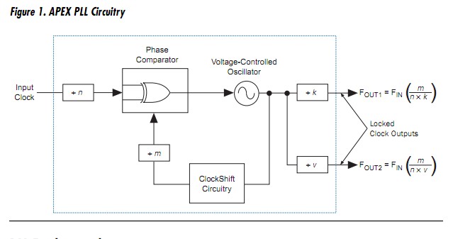
PLL circuits monitor a reference signal, such as a system clock, to manage or synthesize other clocks. In a PLL, a phase comparator measures the difference between the phase and frequency of an external reference signal and an internal feedback signal. Based on this difference, the phase comparator adjusts the voltage-controlled oscillator (VCO), which produces a timing signal clock that is fed back to the phase detector. This signal is compared with the incoming reference signal. When the reference signal and the VCO feedback signal are identical, the PLL is “locked” onto the reference signal. The PLL continues to monitor the reference signal and adjust the VCO output to
compensate for any temperature or voltage fluctuations. Figure 1 shows a block diagram of an APEX PLL
DLL Fundamentals
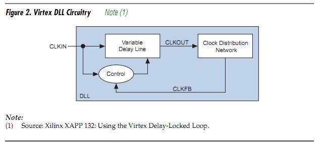
DLL circuits also monitor a reference signal for clock management. The operation of a DLL is fundamentally the same as a PLL, except that a delay line is used instead of a VCO to generate the output timing signal. The delay line inserts a given amount of delay between the input clock and the feedback clock, so that two rising edges align. Figure 2 shows a block diagram of the Virtex DLL.
posted on 2010-08-29 22:38 Homography Matrix 阅读(1313) 评论(1) 编辑 收藏 举报