简易数字电压表+ADC0809+总线方式实现一路数据转换
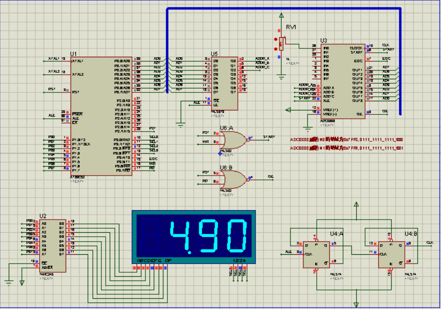
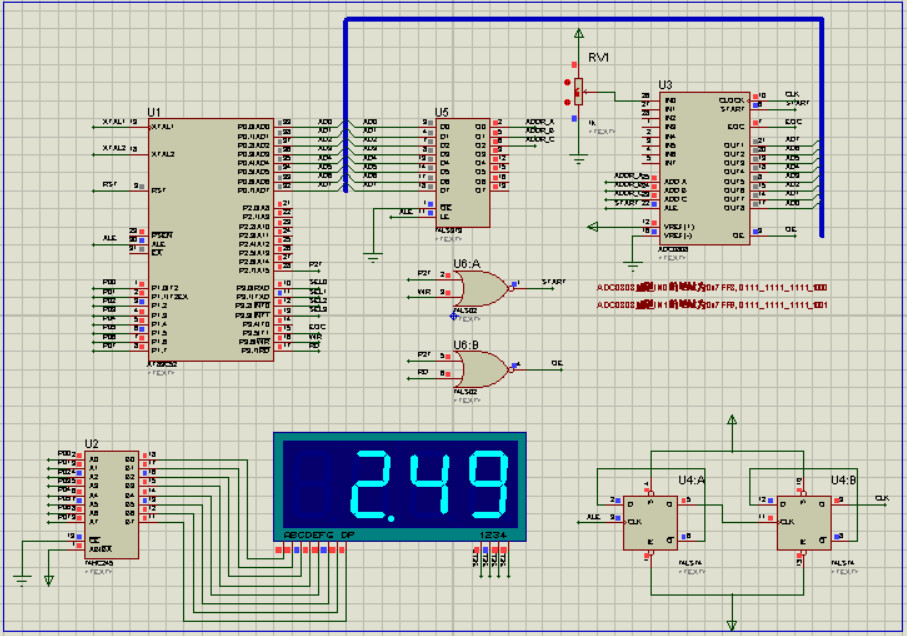
1 实验现象
2 实验原理(略)
3 系统设计(略)
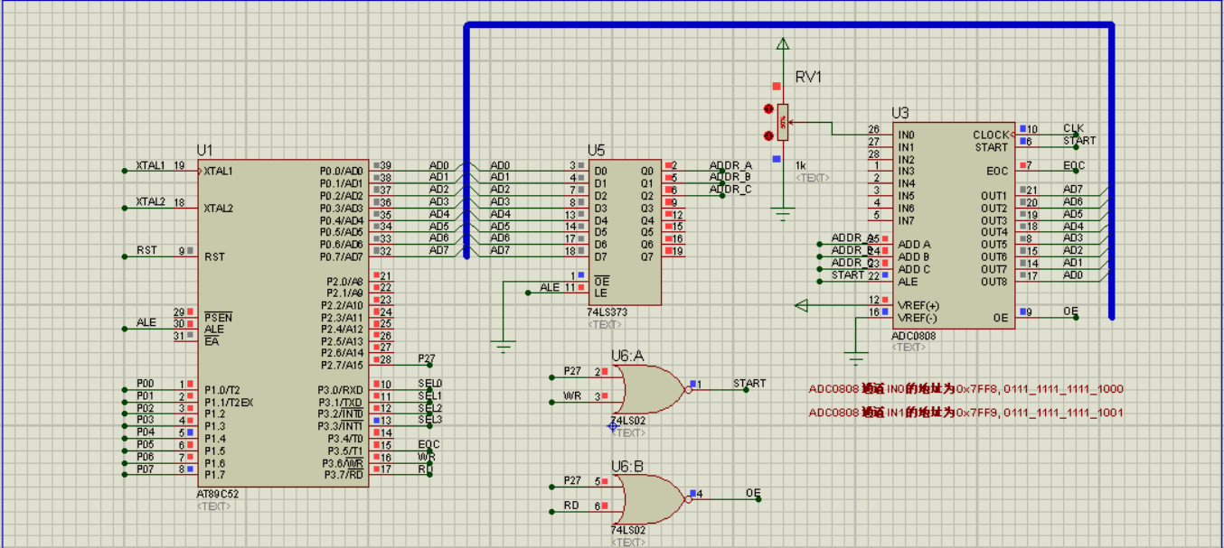
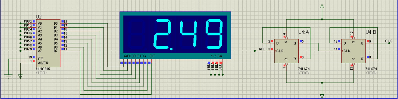
4 硬件设计
5 软件设计
5.1 主函数
#include "DisplaySmg.h"
#include "ADC0809.h"
#include "Timer0.h"

unsigned char adc_result = 0;
int adc_result_show     = 0;
unsigned char adc_flag    = 1;    //启动ADC转换的标志信号

void disp_num()            //将待显示数据放入缓存区
{
    LedBuf[0]= 23;                        //千位,不显示
    LedBuf[1]= adc_result_show/100;        //百位
    LedBuf[2]= adc_result_show/10%10;    //十位
    LedBuf[3]= adc_result_show%10;        //个位
}

void main()
{
    Timer0_Init();        //定时计数器T0初始化
    EA=1;                //中断总开关
    DotDig1=1;            //点亮第二个数码管的小数点
    while(1)
    {

        adc_result = ADC0809_Conv();     //滤波处理,不能只采样一次,应该进行多次采样数字滤波
        adc_result_show = adc_result*1.0*100*5/255;    //数据变换处理(线性标度变换)
        disp_num();            //显示数据
    }
}

void Timer0_ISR(void) interrupt 1
{
    static unsigned int timer0cnt=0;
    TR0=0;                //关闭定时器
    timer0cnt++;
    if(timer0cnt>=500)
    {
        timer0cnt    = 0;
        adc_flag     = 1;    //500ms的标志信号
    }
    DisplaySmg();        //每过1ms,刷新一次数码管显示函数
    TL0 = 0x66;            //设置定时初始值,定时1ms
    TH0 = 0xFC;            //设置定时初始值,定时1ms
    TR0=1;                //打开定时器
}
5.2 ADC0809转换函数(片外RAM,总线方式连接)
#ifndef __ADC0809_H__
#define __ADC0809_H__

#include <reg52.h>
#include <absacc.h>            //含有宏定义的包含语句

#define ADC0809_IN0 XBYTE[0x7ff8]    //地址定义语句

sbit EOC    = P3^5;

unsigned char ADC0809_Conv();

#endif
#include "ADC0809.h"

unsigned char ADC0809_Conv()
{
    unsigned char adc_result=0;

    //选通道,启动ADC转换
    ADC0809_IN0 = 0x0;     //借助对端口地址执行写操作时序,来满足AD的操作时序
    while(EOC==0);        //等待ADC转换结束,EOC变为高电平
    adc_result = ADC0809_IN0;    ////借助对端口地址执行读操作时序,来满足AD的操作时序
    return adc_result;
}
5.3 数码管动态显示函数(定时器刷新)
#ifndef __DisplaySmg_H__
#define __DisplaySmg_H__

#include <REG52.H>

#define GPIO_SEG P1        //段选端
sbit  SEL0 = P3^0;
sbit  SEL1 = P3^1;
sbit  SEL2 = P3^2;
sbit  SEL3 = P3^3;

extern unsigned char LedBuf[];    //外部变量声明
extern unsigned char DotDig0,DotDig1,DotDig2,DotDig3;

void DisplaySmg(void);

#endif
#include "DisplaySmg.h"

unsigned char code LedData[]={    //共阴型数码管的段码表,字符,序号
                0x3F,  //"0",0
                0x06,  //"1",1
                0x5B,  //"2",2
                0x4F,  //"3",3
                0x66,  //"4",4
                0x6D,  //"5",5
                0x7D,  //"6",6
                0x07,  //"7",7
                0x7F,  //"8",8
                0x6F,  //"9",9
                0x77,  //"A",10
                0x7C,  //"B",11
                0x39,  //"C",12
                0x5E,  //"D",13
                0x79,  //"E",14
                0x71,  //"F",15
                0x76,  //"H",16
                0x38,  //"L",17
                0x37,  //"n",18
                0x3E,  //"u",19
                0x73,  //"P",20
                0x5C,  //"o",21
                0x40,  //"-",22
                0x00,  //熄灭 23
                         };
unsigned char DotDig0=0,DotDig1=0,DotDig2=0,DotDig3=0;    //小数点控制位
unsigned char LedBuf[]={22,22,22,22};    //显示缓存区

void DisplaySmg()                    //四位数码管,考虑小数点
{
    unsigned char     i;                 //等价于 "static unsigned char i = 0;"
    unsigned char     temp;
    switch(i)
    {
        case 0:
        {
            GPIO_SEG = 0x00;                //消影
            if(DotDig0==1)                    //小数点
            {
                temp = LedData[LedBuf[0]] | 0x80;  //点亮小数点
            }
            else
            {
                temp = LedData[LedBuf[0]];
            }
            GPIO_SEG = temp;                    //段码
            SEL0=0;    SEL1=1;    SEL2=1;    SEL3=1;        //位选
            i++;
            break;
        }

        case 1:
            GPIO_SEG = 0x00;
            if(DotDig1==1)                    //小数点
            {
                temp = LedData[LedBuf[1]] | 0x80;
            }
            else
            {
                temp = LedData[LedBuf[1]];
            }
            GPIO_SEG = temp;
            SEL0=1;    SEL1=0;    SEL2=1;    SEL3=1;
            i++;
            break;
        case 2:
            GPIO_SEG = 0x00;
            if(DotDig2==1)                    //小数点
            {
                temp = LedData[LedBuf[2]] | 0x80;
            }
            else
            {
                temp = LedData[LedBuf[2]];
            }
            GPIO_SEG = temp;
            SEL0=1;    SEL1=1;    SEL2=0;    SEL3=1;
            i++;
            break;
        case 3:
            GPIO_SEG = 0x00;
            if(DotDig3==1)                    //小数点
            {
                temp = LedData[LedBuf[3]] | 0x80;
            }
            else
            {
                temp = LedData[LedBuf[3]];
            }
            GPIO_SEG = temp;
            SEL0=1;    SEL1=1;    SEL2=1;    SEL3=0;
            i=0;
            break;
        default:break;
    }
}
5.4 定时器T0模块
#ifndef __Timer0_H__
#define __Timer0_H__

#include <reg52.h>

void Timer0_Init(void);

#endif
#include "Timer0.h"

void Timer0_Init(void)        //1毫秒@11.0592MHz
{
    TMOD &= 0xF0;        //设置定时器模式
    TMOD |= 0x01;        //设置定时器模式
    TL0 = 0x66;            //设置定时初始值
    TH0 = 0xFC;            //设置定时初始值
    TF0 = 0;            //清除TF0标志
    TR0 = 1;            //定时器0开始计时

    ET0 = 1;            //定时器0中断开关
//    EA  = 1;             //中断总开关
}


//中断服务函数一定是一个没有返回值的函数
//中断服务函数一定是没有参数的函数
//中断服务函数函数名后跟着关键字interrupt
//interrupt n 0~4 5个中断源,8*n+0003H
// 0003H INT0, 00BH T0, 0013H INT1, 001BH T1, 0023H ES
//中断服务函数不能被主程序或者其他程序所调用
//n后面跟着using m(0~3)工作寄存器组

//void Timer0_ISR(void) interrupt 1
//{
//    TL0 = 0x66;            //设置定时初始值
//    TH0 = 0xFC;            //设置定时初始值
//}
6 参考来源

 浙公网安备 33010602011771号