STM32 特殊的PB4
之前写代码给PB4配置输出模式,上机运行,发现PB4不受控制,一直是高电平。
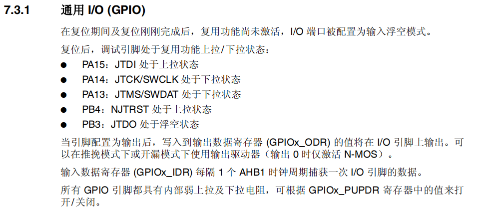
经过学习后得知PB4在系统复位时候,默认SYS_HJTRST,还有PA13、PA14、PA15、PB3同理。

因此,想要使用以上IO口,需要禁止其功能。
标准库“stm32f10x_gpio.h”中存在重映射定义如下:
#define GPIO_Remap_SWJ_NoJTRST ((uint32_t)0x00300100) /*!< Full SWJ Enabled (JTAG-DP + SW-DP) but without JTRST */

#define GPIO_Remap_SWJ_JTAGDisable ((uint32_t)0x00300200) /*!< JTAG-DP Disabled and SW-DP Enabled */

#define GPIO_Remap_SWJ_Disable ((uint32_t)0x00300400) /*!< Full SWJ Disabled (JTAG-DP + SW-DP) */
首先,需要打开重映射时钟和重映射后的I/O口引脚时钟,因为需要先打开复用功能才能修改。
RCC_APB2PeriphClockCmd(RCC_APB2Periph_GPIOB | RCC_APB2Periph_AFIO,ENABLE);
然后重映射,关闭JTAG功能。
GPIO_PinRemapConfig(GPIO_Remap_SWJ_JTAGDisable,ENABLE);
注意,此时因JTAG已经关闭,因此不能使用JTAG烧录程序,只能使用SWD或串口烧录。
之后正常进行端口初始化配置,使能端口。
由于PB4默认处于上拉阶段,如果开机时需要PB4为低电平,还需要进行置位。

GPIO_ResetBits(GPIOB,GPIO_Pin_4);
以上代码将PB4初始拉低。
希望能帮助大家!
一个示例
GPIO_InitTypeDef GPIO_InitStructure;
RCC_APB2PeriphClockCmd(RCC_APB2Periph_GPIOB | RCC_APB2Periph_GPIOC | RCC_APB2Periph_GPIOD | RCC_APB2Periph_AFIO, ENABLE);
GPIO_PinRemapConfig(GPIO_Remap_SWJ_JTAGDisable,ENABLE);
GPIO_InitStructure.GPIO_Pin = GPIO_Pin_1 | GPIO_Pin_4 | GPIO_Pin_5 | GPIO_Pin_6 | GPIO_Pin_7 | GPIO_Pin_12 | GPIO_Pin_13 | GPIO_Pin_14 | GPIO_Pin_15;
GPIO_InitStructure.GPIO_Mode = GPIO_Mode_Out_PP;
GPIO_InitStructure.GPIO_Speed = GPIO_Speed_50MHz;
GPIO_Init(GPIOB, &GPIO_InitStructure);
GPIO_InitStructure.GPIO_Pin = GPIO_Pin_6 | GPIO_Pin_7 | GPIO_Pin_8 | GPIO_Pin_9 | GPIO_Pin_10 | GPIO_Pin_11 | GPIO_Pin_12;
GPIO_InitStructure.GPIO_Mode = GPIO_Mode_Out_PP;
GPIO_InitStructure.GPIO_Speed = GPIO_Speed_50MHz;
GPIO_Init(GPIOC, &GPIO_InitStructure);
GPIO_InitStructure.GPIO_Pin = GPIO_Pin_2;
GPIO_InitStructure.GPIO_Mode = GPIO_Mode_Out_PP;
GPIO_InitStructure.GPIO_Speed = GPIO_Speed_50MHz;
GPIO_Init(GPIOD, &GPIO_InitStructure);
GPIO_ResetBits(GPIOB,GPIO_Pin_4);


 浙公网安备 33010602011771号