DirectX 10学习笔记3: Buffers,Shaders以及HLSL
几个基本概念:
Vertex buffer:存储顶点的数组。当构成模型的所有顶点都放进vertex buffer后,就可以把vertex buffer送进GPU,然后GPU就可以渲染模型了。
Index buffer:这个buffer的作用是索引。记录每个顶点在vertex buffer中的位置。DX SDK里说使用index buffer可以增加顶点数据被缓存在显存里的概率,所以就效率而言应该使用index buffer。
Vertex Shader:vertex shader是一类小程序,主要用来把vertex buffer里的顶点变换到3D空间中去。也可以用vertex shader干点别的,比如算顶点的法向量。对于每个要处理的顶点,GPU都会调用vertex shader。比如5000个三角形的网格模型,每一帧就得调用vertex shader 15000次,每秒60帧的话,vertex shader还真得写得靠谱点。
Pixel Shader:是一般用来处理多边形颜色的小程序。对于场景里每个要画到屏幕上的可见像素,GPU都会调用Pixel Shader来处理。像着色、光照,还有大多数用在多边形上的其他效果,都要靠Pixel Shader来搞定。没错,这个东西也得写的靠谱点。效率,效率啊。要不可能GPU还没有CPU算得快。
HLSL:这就是用来写各种shader程序的语言了。HLSL程序包括全局变量、类型定义、vertex shaders,pixel shaders还有geometry shaders。
程序的整体结构:
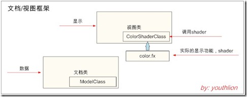
这一次接着上一篇笔记的程序继续扩展。在这篇笔记中,我们会用shader绘制一个绿色的三角形。这里三角形是要绘制的对象,实际上是一个简单的多边形模型,也就是数据,所以把它封装到一个模型类(ModelClass)中,并集成到文档类里去。视图类负责显示,而显示的功能是由shader完成的。正如前面说的,shader是一段小程序,上面的图中集成到视图类中的ColorShaderClass负责调用shader,也就是让这段shader小程序运行起来。这就是这篇笔记中程序的最宏观结构。
第一个shader程序:
在工程中添加一个名为color.fx的源文件,看来shader程序源文件的扩展名是.fx了。这个shader的目的是绘制一个绿色的三角形。
这个shader首先声明了三个全局矩阵变量,便于其他类从外部访问,再传回shader。
/////////////
// GLOBALS //
/////////////
matrix worldMatrix;
matrix viewMatrix;
matrix projectionMatrix;
下面几行代码里,使用HLSL中的float4类型创建了一个位置向量,包括x、y、z、w,以及一个颜色向量,包括red、green、blue、alpha分量。其中POSITION、COLOR和SV_POSITION是传递给GPU的语义信息,让GPU知道这些变量是干嘛用的。下面的两个类型貌似作用是一样的,但是必须分别创建。因为对于vertex shader和pixel shader,需要不同的语义。POSITION是对应vertex shader,SV_POSITION适用于pixel shader,COLOR则是两者通用。如果需要同一类型的多个成员,就得在类型后面加上个数值后缀,像COLOR0、COLOR1这种。
//////////////
// TYPEDEFS //
//////////////
struct VertexInputType
{
float4 position : POSITION;
float4 color : COLOR;
};
struct PixelInputType
{
float4 position : SV_POSITION;
float4 color : COLOR;
};
当vertex buffer中的数据被送进GPU进行处理的时候,GPU会调用vertex shader。下面定义了一个名为ColorVertexShader的函数,该函数在处理vertex buffer中每个顶点的时候都会被调用。vertex shader的输入必须与vertex buffer缓冲区中的数据以及shader源文件中的类型定义相匹配。这里就是VertexInputType。vertex shader的输出会被送进pixel shader,这里输出类型为上面定义的PixelInputType。
下面代码中的vertex shader流程是这样的:他先创建一个输出变量,类型为PixelInputType,然后拿到输入顶点的坐标,把世界矩阵、视点矩阵、投影矩阵挨个乘上去,对顶点进行变换,最后顶点会被变换到我们视点所观察的3D空间中的正确位置。然后拿到输入的颜色值,放进输出变量里,把输出变量返回,返回的输出变量接下来会被送进pixel shader。
////////////////////////////////////////////////////////////////////////////////
// Vertex Shader
////////////////////////////////////////////////////////////////////////////////
PixelInputType ColorVertexShader(VertexInputType input)
{
PixelInputType output;
// Change the position vector to be 4 units for proper matrix calculations.
input.position.w = 1.0f;
// Calculate the position of the vertex against the world, view, and projection matrices.
output.position = mul(input.position, worldMatrix);
output.position = mul(output.position, viewMatrix);
output.position = mul(output.position, projectionMatrix);
// Store the input color for the pixel shader to use.
output.color = input.color;
return output;
}
////////////////////////////////////////////////////////////////////////////////
// Pixel Shader
////////////////////////////////////////////////////////////////////////////////
float4 ColorPixelShader(PixelInputType input) : SV_Target
{
return input.color;
}
下面几行代码里的technique才是真正意义的shader。这个东西是用来渲染多边形、调用vertex shader和pixel shader的,可以把它看做是HLSL的main()函数。在technique里面可以设定多个pass,调用各种vertex shader和pixel shader来组合出想要的效果。这个例子里只使用了一个pass,也只调用了上面写好的vertex和pixel shader。geometry shader暂时不用,这里也没有调用。
还有个值得注意的事儿,代码里用vs_4_0指定vertex shader的版本为4.0,这是SetVertexShader函数的第一个参数。这样我们才可以使用DX10 HLSL中vertex shader4.0相应的功能。pixel shader也是类似。
////////////////////////////////////////////////////////////////////////////////
// Technique
////////////////////////////////////////////////////////////////////////////////
technique10 ColorTechnique
{
pass pass0
{
SetVertexShader(CompileShader(vs_4_0, ColorVertexShader()));
SetPixelShader(CompileShader(ps_4_0, ColorPixelShader()));
SetGeometryShader(NULL);
}
}
以上是这个例子的shader部分。也就是负责实际渲染工作的模块。那么shader渲染的是神马?恩,模型。
所以要在工程里再添加个模型类:
这个例子里,我们的模型仅仅是个三角形,暂时用原教程给的一个模型类ModelClass,后面如果需要,争取把这个模型类用CGAL的Polyhedron替换掉。下面先看一下ModelClass的头文件:
首先在ModelClass中添加顶点类型的定义。这也是vertex buffer的类型。
struct VertexType
{
D3DXVECTOR3 position;
D3DXVECTOR4 color;
};
构造和析构函数:
ModelClass();
ModelClass(const ModelClass&);
~ModelClass();
下面的几个函数负责初始化和释放模型的vertex和index buffer。Render函数负责把模型的几何属性送到显卡上,准备让shader绘制。
bool Initialize(ID3D10Device*);
void Shutdown();
void Render(ID3D10Device*);
int GetIndexCount();
上面的几个公有函数的功能通过调用下面的几个私有函数实现:
private:
bool InitializeBuffers(ID3D10Device*);
void ShutdownBuffers();
void RenderBuffers(ID3D10Device*);
添加几个私有变量,分别作为vertex buffer和index buffer的指针,另外还有两个整型,用来记录两块buffer的大小。注意DX10里buffer一般用通用的ID3D10Buffer类型,这种类型的变量在创建的时候可以用buffer description进行描述。
private:
ID3D10Buffer *m_vertexBuffer, *m_indexBuffer;
int m_vertexCount, m_indexCount;
ModelClass类的实现部分,先是构造和析构函数:
ModelClass::ModelClass()
{
m_vertexBuffer = NULL;
m_indexBuffer = NULL;
}
ModelClass::ModelClass(const ModelClass& other)
{
}
ModelClass::~ModelClass()
{
}
初始化函数:
bool ModelClass::Initialize(ID3D10Device* device)
{
bool result;
// Initialize the vertex and index buffer that hold the geometry for the triangle.
result = InitializeBuffers(device);
if(!result)
{
return false;
}
return true;
}
释放buffer:
void ModelClass::Shutdown()
{
// Release the vertex and index buffers.
ShutdownBuffers();
return;
}
Render函数实际是在框架的绘制模块里调用的,也就是我第二篇笔记中的视图类,再具体点,应该就是在视图类的OnPaint方法里。
void ModelClass::Render(ID3D10Device* device)
{
// Put the vertex and index buffers on the graphics pipeline to prepare them for drawing.
RenderBuffers(device);
return;
}
GetIndexCount函数返回index的数量:
int ModelClass::GetIndexCount()
{
return m_indexCount;
}
接下来是Initialize、ShutDown和Render对应的几个私有方法的具体实现,首先是InitializeBuffers,这个函数负责创建vertex buffer和index buffer。在实际的应用里,一般是从数据文件里把模型读进来(.off,.obj,.ply等等)然后创建buffer,在这个例子里,因为模型只是一个三角形,所以直接在vertex buffer和index buffer里人工设置了三个点。
bool ModelClass::InitializeBuffers(ID3D10Device* device)
{
VertexType* vertices;
unsigned long* indices;
D3D10_BUFFER_DESC vertexBufferDesc, indexBufferDesc;
D3D10_SUBRESOURCE_DATA vertexData, indexData;
HRESULT result;
首先创建两个数组,用来存储顶点和索引数据。后面会用这两个数组去填充最终的buffer。
// Set the number of vertices in the vertex array.
m_vertexCount = 3;
// Set the number of indices in the index array.
m_indexCount = 3;
// Create the vertex array.
vertices = new VertexType[m_vertexCount];
if(!vertices)
{
return false;
}
// Create the index array.
indices = new unsigned long[m_indexCount];
if(!indices)
{
return false;
}
然后分别对顶点属性和顶点索引赋值。留心,下面的代码是按照顺时针的顺序创建顶点的。如果逆时针创建的话,程序会认为这个三角形是屁股朝着屏幕。如果恰好又设置了背面剔除的话,程序就不再绘制这个三角形了。所以说,被送进GPU的顶点顺序是有讲究的。
// Load the vertex array with data.
vertices[0].position = D3DXVECTOR3(-1.0f, -1.0f, 0.0f); // Bottom left.
vertices[0].color = D3DXVECTOR4(0.0f, 1.0f, 0.0f, 1.0f);
vertices[1].position = D3DXVECTOR3(0.0f, 1.0f, 0.0f); // Top middle.
vertices[1].color = D3DXVECTOR4(0.0f, 1.0f, 0.0f, 1.0f);
vertices[2].position = D3DXVECTOR3(1.0f, -1.0f, 0.0f); // Bottom right.
vertices[2].color = D3DXVECTOR4(0.0f, 1.0f, 0.0f, 1.0f);
// Load the index array with data.
indices[0] = 0; // Bottom left.
indices[1] = 1; // Top middle.
indices[2] = 2; // Bottom right.
vetex数组和index数组搞定后,可以用它们来创建vertex buffer和index buffer。两种buffer的创建方式是一样的:首先填好buffer的description。在这个description里面ByteWidth(buffer的大小)和BindFlags(buffer类型)必须得填对。填好description后,还要分别填一个subresource指针,这量个指针分别指向前面创建的vertex数组和index数组。description和subresource都填好之后,就可以用D3D device调用CreateBuffer,这个函数会返回指向新创建buffer的指针。
// Set up the description of the vertex buffer.
vertexBufferDesc.Usage = D3D10_USAGE_DEFAULT;
vertexBufferDesc.ByteWidth = sizeof(VertexType) * m_vertexCount;
vertexBufferDesc.BindFlags = D3D10_BIND_VERTEX_BUFFER;
vertexBufferDesc.CPUAccessFlags = 0;
vertexBufferDesc.MiscFlags = 0;
// Give the subresource structure a pointer to the vertex data.
vertexData.pSysMem = vertices;
// Now finally create the vertex buffer.
result = device->CreateBuffer(&vertexBufferDesc, &vertexData, &m_vertexBuffer);
if(FAILED(result))
{
return false;
}
// Set up the description of the index buffer.
indexBufferDesc.Usage = D3D10_USAGE_DEFAULT;
indexBufferDesc.ByteWidth = sizeof(unsigned long) * m_indexCount;
indexBufferDesc.BindFlags = D3D10_BIND_INDEX_BUFFER;
indexBufferDesc.CPUAccessFlags = 0;
indexBufferDesc.MiscFlags = 0;
// Give the subresource structure a pointer to the index data.
indexData.pSysMem = indices;
// Create the index buffer.
result = device->CreateBuffer(&indexBufferDesc, &indexData, &m_indexBuffer);
if(FAILED(result))
{
return false;
}
vertex buffer和index buffer创建后,就可以卸磨杀驴,干掉vertex数组和index数组了:
// Release the arrays now that the vertex and index buffers have been created and loaded.
delete [] vertices;
vertices = 0;
delete [] indices;
indices = 0;
return true;
}
接下来是负责释放vertex buffer和index buffer的ShutdownBuffers函数:
void ModelClass::ShutdownBuffers()
{
// Release the index buffer.
if(m_indexBuffer)
{
m_indexBuffer->Release();
m_indexBuffer = 0;
}
// Release the vertex buffer.
if(m_vertexBuffer)
{
m_vertexBuffer->Release();
m_vertexBuffer = 0;
}
return;
}
下面是对应Render函数的私有函数RenderBuffers。这个函数的作用是把GPU中input assembler上的vertex buffer和index buffer设置为激活状态。一旦有了一块激活的vertex buffer,GPU就可以用我们写的HLSL shader去渲染这块buffer。RenderBuffers函数还规定了这些buffer的绘制方式,比如绘制三角形、绘制直线神马的。这一篇笔记里,我们在input assembler上激活index buffer和vertex buffer,并通过DX10的IASetPrimitiveTopology函数告诉GPU,这块buffer要以三角形的方式绘制。
void ModelClass::RenderBuffers(ID3D10Device* device)
{
unsigned int stride;
unsigned int offset;
// Set vertex buffer stride and offset.
stride = sizeof(VertexType);
offset = 0;
// Set the vertex buffer to active in the input assembler so it can be rendered.
device->IASetVertexBuffers(0, 1, &m_vertexBuffer, &stride, &offset);
// Set the index buffer to active in the input assembler so it can be rendered.
device->IASetIndexBuffer(m_indexBuffer, DXGI_FORMAT_R32_UINT, 0);
// Set the type of primitive that should be rendered from this vertex buffer, in this case triangles.
device->IASetPrimitiveTopology(D3D10_PRIMITIVE_TOPOLOGY_TRIANGLELIST);
return;
}
Model类搞定。整理一下宏观的思路:现在我们有了模型,也有了shader,可以用shader去渲染模型了。
问题在于,shader是怎样开始运行的呢?
我们用下面这个ColorShaderClass类来调用shader。
这个类的Initialize和Shutdown两个成员函数完成对shader的初始化和关闭,Render成员函数负责设置shader的参数,然后用shader去绘制模型。
ColorShaderClass类包含的头文件及类声明如下:
#include <d3d10.h>
#include <d3dx10math.h>
#include <fstream>
using namespace std;
class ColorShaderClass
{
public:
ColorShaderClass();
ColorShaderClass(const ColorShaderClass&);
~ColorShaderClass();
bool Initialize(ID3D10Device*, HWND);
void Shutdown();
void Render(ID3D10Device*, int, D3DXMATRIX, D3DXMATRIX, D3DXMATRIX);
private:
bool InitializeShader(ID3D10Device*, HWND, WCHAR*);
void ShutdownShader();
void OutputShaderErrorMessage(ID3D10Blob*, HWND, WCHAR*);
void SetShaderParameters(D3DXMATRIX, D3DXMATRIX, D3DXMATRIX);
void RenderShader(ID3D10Device*, int);
private:
ID3D10Effect* m_effect;
ID3D10EffectTechnique* m_technique;
ID3D10InputLayout* m_layout;
ID3D10EffectMatrixVariable* m_worldMatrixPtr;
ID3D10EffectMatrixVariable* m_viewMatrixPtr;
ID3D10EffectMatrixVariable* m_projectionMatrixPtr;
};
bool ColorShaderClass::Initialize(ID3D10Device* device, HWND hwnd)
{
bool result;
// Initialize the shader that will be used to draw the triangle.
result = InitializeShader(device, hwnd, L"../02_01/color.fx");
if(!result)
{
return false;
}
return true;
}
Shutdown调用ShutdownShader关闭shader:
void ColorShaderClass::Shutdown()
{
// Shutdown the shader effect.
ShutdownShader();
return;
}
Render函数里做两件事:1、设置shader参数,通过SetShaderParameters完成;2、用shader绘制绿三角,调用RenderShader完成:
void ColorShaderClass::Render(ID3D10Device* device, int indexCount, D3DXMATRIX worldMatrix, D3DXMATRIX viewMatrix, D3DXMATRIX projectionMatrix)
{
// Set the shader parameters that it will use for rendering.
SetShaderParameters(worldMatrix, viewMatrix, projectionMatrix);
// Now render the prepared buffers with the shader.
RenderShader(device, indexCount);
return;
}
在下面的InitializeShader函数中我们可以看到,shader实际上是在这里加载的。在这个函数里,我们还需要设置一个layout,这个layout需要与模型类及color.fx类中定义的顶点类相匹配:
bool ColorShaderClass::InitializeShader(ID3D10Device* device, HWND hwnd, WCHAR* filename)
{
HRESULT result;
ID3D10Blob* errorMessage;
D3D10_INPUT_ELEMENT_DESC polygonLayout[2];
unsigned int numElements;
D3D10_PASS_DESC passDesc;
// Initialize the error message.
errorMessage = 0;
在D3DX10CreateEffectFromFile函数中,shader程序被编译为一个effect。这个函数的几个重要参数包括shader文件名、shader版本(DX10是4.0)、还要制定要把shader编译到哪个effect里去(对应ColorShaderClass类的m_effect成员)。如果在编译shader的过程中失败的话,D3DX10CreateEffectFromFile会把一条错误消息放到errorMessage里,我们会把这个字符串塞给另一个函数OutputShaderErrorMessage去输出错误信息。要是编译失败了,却还没有错误信息的话,可能是找不到shader文件,对这种情况我们会弹出一个对话框作为提示。
// Load the shader in from the file.
result = D3DX10CreateEffectFromFile(filename, NULL, NULL, "fx_4_0", D3D10_SHADER_ENABLE_STRICTNESS, 0,
device, NULL, NULL, &m_effect, &errorMessage, NULL);
if(FAILED(result))
{
// If the shader failed to compile it should have writen something to the error message.
if(errorMessage)
{
OutputShaderErrorMessage(errorMessage, hwnd, filename);
}
// If there was nothing in the error message then it simply could not find the shader file itself.
else
{
MessageBox(hwnd, filename, L"Missing Shader File", MB_OK);
}
return false;
}
当shader文件成功编译为effect后,就可以用这个effect找到shader里的那个technique。我们后面用这个technique进行绘制:
// Get a pointer to the technique inside the shader.
m_technique = m_effect->GetTechniqueByName("ColorTechnique");
if(!m_technique)
{
return false;
}
下一步,shader所处理的顶点,还需要创建并设置一个layout。在这一篇笔记里,shader使用了一个位置向量和一个颜色向量,所以我们在layout中也要创建对应的元素,用来指明位置和颜色信息的内存占用情况。首先要填充的是语义信息,这样shader才能知道这个layout元素的用途。对于位置信息,我们使用POSITION,颜色信息用COLOR。另一个重要信息是格式,位置信息我们用DXGI_FORMAT_R32G32B32_FLOAT,颜色信息用DXGI_FORMAT_R32G32B32A32_FLOAT。最后要注意的是AlignedByteOffset,这个字段指定了buffer中数据存储的起点。对于本例来说,前12个字节是位置,随后的16个字节是颜色。这个字段可以用D3D10_APPEND_ALIGNED_ELEMENT代替,表示DX10会自动计算。layout的其他字段暂时不会用到,这里使用默认设置:
// Now setup the layout of the data that goes into the shader.
// This setup needs to match the VertexType stucture in the ModelClass and in the shader.
polygonLayout[0].SemanticName = "POSITION";
polygonLayout[0].SemanticIndex = 0;
polygonLayout[0].Format = DXGI_FORMAT_R32G32B32_FLOAT;
polygonLayout[0].InputSlot = 0;
polygonLayout[0].AlignedByteOffset = 0;
polygonLayout[0].InputSlotClass = D3D10_INPUT_PER_VERTEX_DATA;
polygonLayout[0].InstanceDataStepRate = 0;
polygonLayout[1].SemanticName = "COLOR";
polygonLayout[1].SemanticIndex = 0;
polygonLayout[1].Format = DXGI_FORMAT_R32G32B32A32_FLOAT;
polygonLayout[1].InputSlot = 0;
polygonLayout[1].AlignedByteOffset = D3D10_APPEND_ALIGNED_ELEMENT;
polygonLayout[1].InputSlotClass = D3D10_INPUT_PER_VERTEX_DATA;
polygonLayout[1].InstanceDataStepRate = 0;
layout数组设置好之后,我们计算一下它包含的元素个数,然后用device创建input layout。
// Get a count of the elements in the layout.
numElements = sizeof(polygonLayout) / sizeof(polygonLayout[0]);
// Get the description of the first pass described in the shader technique.
m_technique->GetPassByIndex(0)->GetDesc(&passDesc);
// Create the input layout.
result = device->CreateInputLayout(polygonLayout, numElements, passDesc.pIAInputSignature, passDesc.IAInputSignatureSize,
&m_layout);
if(FAILED(result))
{
return false;
}
下面要做的是获取shader里面那三个矩阵的指针,这样以后就能用这三个指针设置矩阵的值:
// Get pointers to the three matrices inside the shader so we can update them from this class.
m_worldMatrixPtr = m_effect->GetVariableByName("worldMatrix")->AsMatrix();
m_viewMatrixPtr = m_effect->GetVariableByName("viewMatrix")->AsMatrix();
m_projectionMatrixPtr = m_effect->GetVariableByName("projectionMatrix")->AsMatrix();
return true;
}
ShutdownShader函数负责释放资源:
void ColorShaderClass::ShutdownShader()
{
// Release the pointers to the matrices inside the shader.
m_worldMatrixPtr = 0;
m_viewMatrixPtr = 0;
m_projectionMatrixPtr = 0;
// Release the pointer to the shader layout.
if(m_layout)
{
m_layout->Release();
m_layout = 0;
}
// Release the pointer to the shader technique.
m_technique = 0;
// Release the pointer to the shader.
if(m_effect)
{
m_effect->Release();
m_effect = 0;
}
return;
}
在编译vertex shader或pixelshader时若发生问题,错误信息由OutputShaderErrorMessage函数输出:
void ColorShaderClass::OutputShaderErrorMessage(ID3D10Blob* errorMessage, HWND hwnd, WCHAR* shaderFilename)
{
char* compileErrors;
unsigned long bufferSize, i;
ofstream fout;
// Get a pointer to the error message text buffer.
compileErrors = (char*)(errorMessage->GetBufferPointer());
// Get the length of the message.
bufferSize = errorMessage->GetBufferSize();
// Open a file to write the error message to.
fout.open("shader-error.txt");
// Write out the error message.
for(i=0; i<bufferSize; i++)
{
fout << compileErrors[i];
}
// Close the file.
fout.close();
// Release the error message.
errorMessage->Release();
errorMessage = 0;
// Pop a message up on the screen to notify the user to check the text file for compile errors.
MessageBox(hwnd, L"Error compiling shader. Check shader-error.txt for message.", shaderFilename, MB_OK);
return;
}
SetShaderParameters函数便于我们设置shader中的全局变量。这个函数中的三个矩阵是在上一篇笔记中的视图类里创建的,矩阵被创建之后,负责绘图的代码会调用这个函数,把这三个矩阵送进shader。
void ColorShaderClass::SetShaderParameters(D3DXMATRIX worldMatrix, D3DXMATRIX viewMatrix, D3DXMATRIX projectionMatrix)
{
// Set the world matrix variable inside the shader.
m_worldMatrixPtr->SetMatrix((float*)&worldMatrix);
// Set the view matrix variable inside the shader.
m_viewMatrixPtr->SetMatrix((float*)&viewMatrix);
// Set the projection matrix variable inside the shader.
m_projectionMatrixPtr->SetMatrix((float*)&projectionMatrix);
return;
}
SetShaderParameters函数执行后,各种参数(这里实际就是那仨矩阵)设置完成,ColorShaderClass类随后调用RenderShader,RenderShader通过technique指针调用color.fx文件中的shader程序。
RenderShader函数上来先把input layout激活,这样GPU才能知道vertex buffer里数据的格式。接下来要从shader中获取technique的描述,这个technique告诉GPU调用哪个vertex shader或pixel shader来绘制vertex buffer里的数据。本例中我们获取的是color.fx中ColorTechnique的描述,然后通过device调用DrawIndexed函数,循环调用technique中的各个pass来渲染三角形。目前的例子里,shader只有一个pass(pass0)。
void ColorShaderClass::RenderShader(ID3D10Device* device, int indexCount)
{
D3D10_TECHNIQUE_DESC techniqueDesc;
unsigned int i;
// Set the input layout.
device->IASetInputLayout(m_layout);
// Get the description structure of the technique from inside the shader so it can be used for rendering.
m_technique->GetDesc(&techniqueDesc);
// Go through each pass in the technique (should be just one currently) and render the triangles.
for(i=0; i<techniqueDesc.Passes; ++i)
{
m_technique->GetPassByIndex(i)->Apply(0);
device->DrawIndexed(indexCount, 0, 0);
}
return;
}
到这里,我们搞定了一个HLSL shader,设置了vertex buffer和index buffer,并了解了如何调用shader绘制两种buffer中的数据。除此之外,还有一些辅助性的工作要做。第一个问题是,我们绘制的那些内容,是相对于哪个视点的?
好吧,所以我们还需要来个镜头类:
镜头类告诉DX10,镜头是从哪里、以及怎样去观察场景的。镜头类会始终跟踪镜头的位置及其旋转,使用位置和旋转信息生成一个视点矩阵,这个视点矩阵会传进shader,用于渲染。
镜头类声明如下:
#include <d3dx10math.h>
class CameraClass
{
public:
CameraClass();
CameraClass(const CameraClass&);
~CameraClass();
void SetPosition(float, float, float);
void SetRotation(float, float, float);
D3DXVECTOR3 GetPosition();
D3DXVECTOR3 GetRotation();
void Render();
void GetViewMatrix(D3DXMATRIX&);
private:
float m_positionX, m_positionY, m_positionZ;
float m_rotationX, m_rotationY, m_rotationZ;
D3DXMATRIX m_viewMatrix;
};
其中,SetPosition和SetRotation函数用来设置镜头对象的位置和旋转。Render函数基于位置和旋转信息创建视点矩阵。GetViewMatrix用来访问视点矩阵。
构造函数把位置和旋转设置为场景的原点:
CameraClass::CameraClass()
{
m_positionX = 0.0f;
m_positionY = 0.0f;
m_positionZ = 0.0f;
m_rotationX = 0.0f;
m_rotationY = 0.0f;
m_rotationZ = 0.0f;
}
CameraClass::CameraClass(const CameraClass& other)
{
}
CameraClass::~CameraClass()
{
}
两个set函数:
void CameraClass::SetPosition(float x, float y, float z)
{
m_positionX = x;
m_positionY = y;
m_positionZ = z;
return;
}
void CameraClass::SetRotation(float x, float y, float z)
{
m_rotationX = x;
m_rotationY = y;
m_rotationZ = z;
return;
}
两个get函数:
D3DXVECTOR3 CameraClass::GetPosition()
{
return D3DXVECTOR3(m_positionX, m_positionY, m_positionZ);
}
D3DXVECTOR3 CameraClass::GetRotation()
{
return D3DXVECTOR3(m_rotationX, m_rotationY, m_rotationZ);
}
Render函数用位置和旋转信息构造和更新视点矩阵。这里除了位置和旋转,还需要指定一个“上”方向和镜头朝向。接下来,首先在原点处根据x,y,z的值旋转镜头,旋转之后再把镜头移动到三维空间中的指定位置上。当位置、旋转、方向“上”和所观察的位置都确定下来后,就可以用DX10中的D3DXMatrixLookAtLH函数创建视点矩阵了:
void CameraClass::Render()
{
D3DXVECTOR3 up, position, lookAt;
float yaw, pitch, roll;
D3DXMATRIX rotationMatrix;
// Setup the vector that points upwards.
up.x = 0.0f;
up.y = 1.0f;
up.z = 0.0f;
// Setup the position of the camera in the world.
position.x = m_positionX;
position.y = m_positionY;
position.z = m_positionZ;
// Setup where the camera is looking by default.
lookAt.x = 0.0f;
lookAt.y = 0.0f;
lookAt.z = 1.0f;
// Set the yaw (Y axis), pitch (X axis), and roll (Z axis) rotations in radians.
pitch = m_rotationX * 0.0174532925f;
yaw = m_rotationY * 0.0174532925f;
roll = m_rotationZ * 0.0174532925f;
// Create the rotation matrix from the yaw, pitch, and roll values.
D3DXMatrixRotationYawPitchRoll(&rotationMatrix, yaw, pitch, roll);
// Transform the lookAt and up vector by the rotation matrix so the view is correctly rotated at the origin.
D3DXVec3TransformCoord(&lookAt, &lookAt, &rotationMatrix);
D3DXVec3TransformCoord(&up, &up, &rotationMatrix);
// Translate the rotated camera position to the location of the viewer.
lookAt = position + lookAt;
// Finally create the view matrix from the three updated vectors.
D3DXMatrixLookAtLH(&m_viewMatrix, &position, &lookAt, &up);
return;
}
GetViewMatrix:
void CameraClass::GetViewMatrix(D3DXMATRIX& viewMatrix)
{
viewMatrix = m_viewMatrix;
return;
}
至此,我们搞定了负责渲染的shader、负责调用shader的ColorShaderClass、用来存储模型的ModelClass,以及负责管理视点信息的CamaraClass。
下面的故事是,在MFC的MDI框架中,应该怎样用这些类?
从功能上看,文档和视图分别对应数据和显示,在这个例子里,模型是数据(ModelClass),ColorShaderClass实现显示(实际上是shader,color.fx),所以模型嵌入到文档类,而ColorShaderClass集成进视图类。
在文档类中添加ModelClass类指针,这里为了访问方便,直接设置为public:
#include "ModelClass.h"
class CMy02_01Doc : public CDocument
{
...
public:
ModelClass * m_pMesh;
...
};
目前文档类要改的有三处:
构造函数:
CMy02_01Doc::CMy02_01Doc()
{
// TODO: add one-time construction code here
m_pMesh = NULL;
}
在新建文档时创建模型:
BOOL CMy02_01Doc::OnNewDocument()
{
if (!CDocument::OnNewDocument())
return FALSE;
// TODO: add reinitialization code here
// (SDI documents will reuse this document)
m_pMesh = new ModelClass();
return TRUE;
}
关闭文档时释放内存:
CMy02_01Doc::~CMy02_01Doc()
{
if(m_pMesh)
{
m_pMesh->Shutdown();
delete m_pMesh;
m_pMesh = NULL;
}
}
接下来是显示相关的内容。镜头类和ColorShaderClass类都集成到视图类中。
#include <CameraClass.h>
#include <Colorshaderclass.h>
class CMy02_01View : public CView
{
...
CameraClass * m_Camara;
ColorShaderClass * m_ColorShader;
...
};
构造函数:
CMy02_01View::CMy02_01View()
{
// TODO: add construction code here
...
m_Camara = NULL;
m_ColorShader = NULL;
}
给视图类添加一个建立camera、shader对象并进行初始化的函数ShaderInitialize,由于模型是在文档类里创建和销毁的,所以这里只要弄一个临时指针指向模型对象就行了,不需要操心资源管理的事儿:
bool CMy02_01View::ShaderInitialize()
{
bool result;
HWND hwnd = GetSafeHwnd();
// Create the camera object.
m_Camera = new CameraClass();
if(!m_Camera)
{
return false;
}
// Set the initial position of the camera.
m_Camera->SetPosition(0.0f, 0.0f, -10.0f);
// Create the model object.
ModelClass * pmesh = ((CMy02_01Doc *)GetDocument())->m_pMesh;
if(!pmesh)
{
MessageBox(L"NULL Model!!");
return false;
}
result = pmesh->Initialize(m_device);
if(!result)
{
MessageBox(L"Could not initialize the model object.");
return false;
}
// Create the color shader object.
m_ColorShader = new ColorShaderClass();
if(!m_ColorShader)
{
return false;
}
// Initialize the color shader object.
result = m_ColorShader->Initialize(m_device, hwnd);
if(!result)
{
MessageBox(L"Could not initialize the color shader object.");
return false;
}
return true;
}
这个初始化函数在OnInitialUpdate中DX环境初始化后调用:
void CMy02_01View::OnInitialUpdate()
{
CView::OnInitialUpdate();
// TODO: Add your specialized code here and/or call the base class
InitDX();
ShaderInitialize();
}
再添加一个相应的资源释放函数,该函数在视图类的析构函数中调用:
void CMy02_01View::ShutDownShader()
{
// Release the color shader object.
if(m_ColorShader)
{
m_ColorShader->Shutdown();
delete m_ColorShader;
m_ColorShader = NULL;
}
// Release the camera object.
if(m_Camera)
{
delete m_Camera;
m_Camera = 0;
}
}
最后在OnPaint中完成绘制功能:
void CMy02_01View::OnPaint()
{
D3DXMATRIX viewMatrix, projectionMatrix, worldMatrix;
CPaintDC dc(this); // device context for painting
// TODO: Add your message handler code here
// Do not call CView::OnPaint() for painting messages
float color[4];
// Setup the color to clear the buffer to.
color[0] = 1.0f;
color[1] = 0.0f;
color[2] = 0.0f;
color[3] = 1.0f;
// Clear the back buffer.
m_device->ClearRenderTargetView(m_renderTargetView, color);
// Clear the depth buffer.
m_device->ClearDepthStencilView(m_depthStencilView, D3D10_CLEAR_DEPTH, 1.0f, 0);
// Generate the view matrix based on the camera's position.
m_Camera->Render();
// Get the world, view, and projection matrices from the camera and d3d objects.
m_Camera->GetViewMatrix(viewMatrix);
GetWorldMatrix(worldMatrix);
GetProjectionMatrix(projectionMatrix);
ModelClass * pmesh = ((CMy02_01Doc *)GetDocument())->m_pMesh;
pmesh->Render(m_device);
// Render the model using the color shader.
m_ColorShader->Render(m_device, pmesh->GetIndexCount(), worldMatrix, viewMatrix, projectionMatrix);
if(m_vsync_enabled)
{
// Lock to screen refresh rate.
m_swapChain->Present(1, 0);
}
else
{
// Present as fast as possible.
m_swapChain->Present(0, 0);
}
}
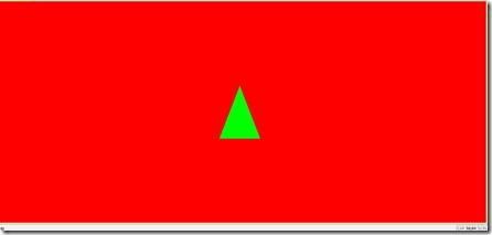
运行效果,弱爆了T_T
下面理一理头绪,回忆一下,上面的shader、ColorShaderClass、ModelClass、CameraClass都是咋回事儿来着?
shader:
(1)它是一个扩展名为.fx的文件
(2)它的入口是technique,这玩意好比main
(3)shader里面还为vertex shader和pixel shader分别定义了顶点类型
(4)分别实现了vertex shader和pixel shader函数
(5)vertex buffer里的数据送进GPU后,会先让vertex shader处理,然后再送进pixel shader
(6)别忘了类型匹配那些事儿
ModelClass:
(1)这是一个模型类,虽然现在这个模型很简单
(2)模型类创建了vertex buffer(注意顶点顺序)和index buffer,并且设置了具体的值(也就是把三角形的各个顶点坐标和颜色值都写进了buffer里面)
(3)模型类激活了vertex buffer和index buffer,让GPU知道,这块数据可以进行绘制了。
(4)模型类告诉GPU,用三角形的方式绘制buffer里的内容
ColorShaderClass:
(1)ColorShaderClass是用来调用shader的
(2)ColorShaderClass要创建并设置与shader中定义的顶点类型匹配的layout,让GPU知道vertex buffer中数据的格式
(3)ColorShaderClass会获取shader中那三个全局矩阵的指针,并设置这三个矩阵的值
(4)ColorShaderClass会获取technique的描述,让GPU知道调用哪些shader函数去绘制,然后循环调用technique中的各个pass进行绘制
CameraClass:
(1)它会设置镜头位置和旋转角度
(2)它会根据镜头位置和旋转角度生成视点变换矩阵
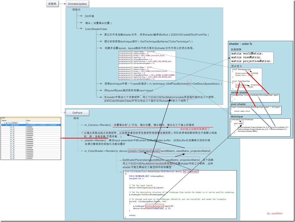
最后,还有一幅恶心的大图,描述了程序的整个流程和关键数据的传输途径:
PS:英文原文教程地址http://www.rastertek.com/dx10tut04.html,根据自己的需要进行了小小改动。
刚刚接触DX,很多背景知识不懂,希望过路的朋友不吝指教,帮我进步。谢谢。
posted on 2012-12-07 21:44 youthlion 阅读(2596) 评论(0) 编辑 收藏 举报


