scan chain的原理和实现——5.UDTP
UDTP(user defined test point)
指示DFTC在设计中用户指定的位置插入控制点和观察点
1.为什么要使用UDTP?
修复无法控制的clock和/或asynch pins;
增加设计的测试覆盖率;
减少pattern数量
2.UDTP的类型
①Force
force_0、force_1、force_01、force_z0、force_z1、force_z01


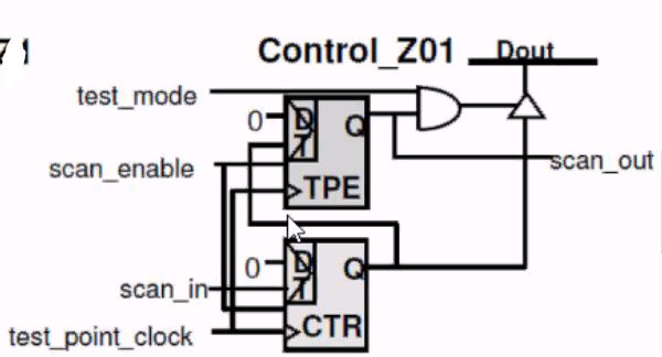
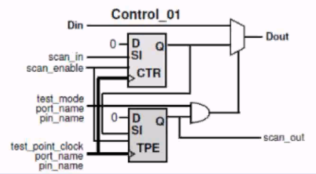
②Control
control_0、control_1、control_01、control_z0、control_z1、 control_z01

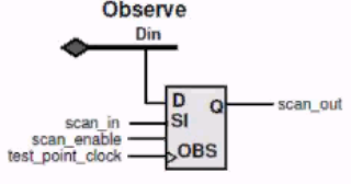
③Observe
observe


3.使用set_test_point_element
set_test_point_element [pin list] -type <test_point_type>
pin list指定了插入UDTP的位置,type只可指定一种类型的type
4.示例——定义control and clock signals
control signals
需要先定义过testmode或scanenable
set_test_point_element pin_list -type control_01 -control_signal port_name l pin_name
clock signals
需要先定义过scanclock
set_test_point_element pin_list -type control_01 -clock_signal port_name | pin_name


#Read in the design and synthesize it
acs_read hdl -hdl_source ./rt1/verilog A_DESGN
llink
compile -scan
#Define the clocks and asynchs in the design
set_dft_signal -type scanclock -view exist -timing {45 55] -port CLK1
set_dft_signal -type scanclock -view exist -timing { 45 55] -port CLK2
set_dft_signal -type Reset -view exist -active 0 -port RST_N
set_dft_signal -type TestMode -active 1 -port TM
set_scan_configuration -chain_count 10 . . .
#UDTP specification. Specify observe and control TPs
#Turn power saving ON for observe test points
set_test_point_element -type observe -power_saving enable -clock_signal CLK1 {alpha_1/Q beta_5/out gamma_3/Q}
#use an existing clock as clock signal and existing port as control signal for control TP
set_test_point_element -type control_1 {u3/omega_2/q alpha_7/Q} -clock_siqnal CLK2 -control_siqnal TM
#Run pre-DRC
create_test_protocol -capture_procedure multi_clock
dft_drc -verbose
#Preview the scan chains
preview_dft -show all -test_points all
#scan insertion
insert_dft
#Run post-DRC
dft_drc -verbose
report_scan_ path -view exist
#write out the netlist
change_names -rules verilog -hier
write -hier -f ddc -out A_DESIGN_udtp_scan.ddc
write -hier -f verilog -out TEST_udtp_scan.v


