Verilog 之 LFSR伪随机数 (转载)
转载:http://blog.csdn.net/hengzo/article/details/49689725
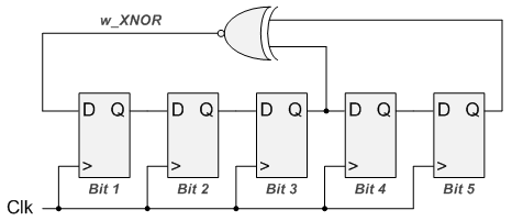
The linear feedback shift register is implemented as a series of Flip-Flops inside of an FPGA that are wired together as a shift register. Several taps off of the shift register chain are used as inputs to either an XOR or XNOR gate. The output of this gate is then used as feedback to the beginning of the shift register chain, hence the Feedback in LFSR.

- LFSR patterns are pseudo-random.
- Output patterns are deterministic. You can figure out the next state by knowing the position of the XOR gates as well as the current pattern.
- A pattern of all 0's cannot appear when the taps use XOR gates. Since 0 XORed with 0 will always produce 0, the LFSR will stop running.注意初始化种子
- A pattern of all 1's cannot appear when the taps use XNOR gates. Since 1 XNORed with 1 will always produce 1, the LFSR will stop running.
- The maximum possible number of iterations of any LFSR = 2Bits-1
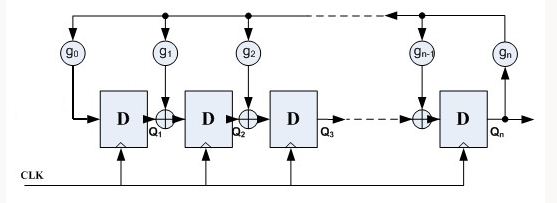
产生伪随机数的方法最常见的是利用一种线性反馈移位寄存器(LFSR)。它是由n个D触发器和若干个异或门组成的,如图:

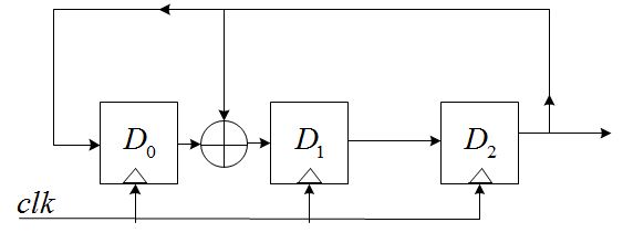
其中,gn为反馈系数,取值只能为0或1,取为0时表明不存在该反馈之路,取为1时表明存在该反馈之路;n个D触发器最多可以提供2^n-1个状态(不包括全0的状态),为了保证这些状态没有重复,gn的选择必须满足一定的条件。下面以n=3,g0=1,g1=1,g2=0,g3=1为例,说明LFSR的特性,具有该参数的LFSR结构如下图:

假设在开始时,D2D1D0=111(seed),那么,当时钟到来时,有:
D2=D1_OUT=1;
D1=D0_OUT^D2_OUT=0;
D0=D2_OUT=1;
即D2D1D0=101;同理,又一个时钟到来时,可得D2D1D0=001. ………………
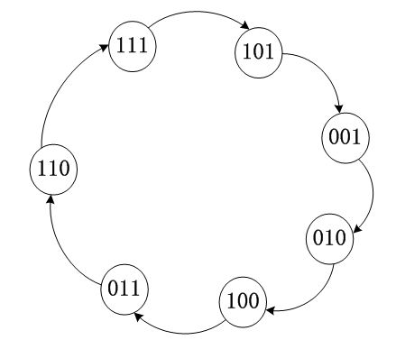
画出状态转移图如下:

从图可以看出,正好有2^3-1=7个状态,不包括全0;
如果您理解了上图,至少可以得到三条结论:
1)初始状态是由SEED提供的;
2)当反馈系数不同时,得到的状态转移图也不同;必须保证gn===1。
3)D触发器的个数越多,产生的状态就越多,也就越“随机”;
verilog实现
  1 <pre name="code" class="plain">//文章地址:http://www.nandland.com/vhdl/modules/lfsr-linear-feedback-shift-register.html
  2 //程序地址:http://www.nandland.com/verilog/modules/code/LFSR.v
  3
  4
  5 ///////////////////////////////////////////////////////////////////////////////
  6 // File downloaded from http://www.nandland.com
  7 ///////////////////////////////////////////////////////////////////////////////
  8 // Description:
  9 // A LFSR or Linear Feedback Shift Register is a quick and easy way to generate
 10 // pseudo-random data inside of an FPGA.  The LFSR can be used for things like
 11 // counters, test patterns, scrambling of data, and others.  This module
 12 // creates an LFSR whose width gets set by a parameter.  The o_LFSR_Done will
 13 // pulse once all combinations of the LFSR are complete.  The number of clock
 14 // cycles that it takes o_LFSR_Done to pulse is equal to 2^g_Num_Bits-1.  For
 15 // example setting g_Num_Bits to 5 means that o_LFSR_Done will pulse every
 16 // 2^5-1 = 31 clock cycles.  o_LFSR_Data will change on each clock cycle that
 17 // the module is enabled, which can be used if desired.
 18 //
 19 // Parameters:
 20 // NUM_BITS - Set to the integer number of bits wide to create your LFSR.
 21 ///////////////////////////////////////////////////////////////////////////////
 22 module LFSR #(parameter NUM_BITS)
 23   (
 24    input i_Clk,
 25    input i_Enable,
 26
 27    // Optional Seed Value
 28    input i_Seed_DV,
 29    input [NUM_BITS-1:0] i_Seed_Data,
 30
 31    output [NUM_BITS-1:0] o_LFSR_Data,
 32    output o_LFSR_Done
 33    );
 34
 35   reg [NUM_BITS:1] r_LFSR = 0;
 36   reg              r_XNOR;
 37
 38
 39   // Purpose: Load up LFSR with Seed if Data Valid (DV) pulse is detected.
 40   // Othewise just run LFSR when enabled.
 41   // 初始化seed值可以选择载入,
 42   always @(posedge i_Clk)
 43     begin
 44       if (i_Enable == 1'b1)
 45         begin
 46           if (i_Seed_DV == 1'b1)
 47             r_LFSR <= i_Seed_Data;
 48           else
 49             r_LFSR <= {r_LFSR[NUM_BITS-1:1], r_XNOR};
 50         end
 51     end
 52
 53   // Create Feedback Polynomials.  Based on Application Note:
 54   // http://www.xilinx.com/support/documentation/application_notes/xapp052.pdf
 55   //使用同或运算,初始化种子不能全1
 56
 57
 58   always @(*)
 59     begin
 60       case (NUM_BITS)
 61         3: begin
 62           r_XNOR = r_LFSR[3] ^~ r_LFSR[2];
 63         end
 64         4: begin
 65           r_XNOR = r_LFSR[4] ^~ r_LFSR[3];
 66         end
 67         5: begin
 68           r_XNOR = r_LFSR[5] ^~ r_LFSR[3];
 69         end
 70         6: begin
 71           r_XNOR = r_LFSR[6] ^~ r_LFSR[5];
 72         end
 73         7: begin
 74           r_XNOR = r_LFSR[7] ^~ r_LFSR[6];
 75         end
 76         8: begin
 77           r_XNOR = r_LFSR[8] ^~ r_LFSR[6] ^~ r_LFSR[5] ^~ r_LFSR[4];
 78         end
 79         9: begin
 80           r_XNOR = r_LFSR[9] ^~ r_LFSR[5];
 81         end
 82         10: begin
 83           r_XNOR = r_LFSR[10] ^~ r_LFSR[7];
 84         end
 85         11: begin
 86           r_XNOR = r_LFSR[11] ^~ r_LFSR[9];
 87         end
 88         12: begin
 89           r_XNOR = r_LFSR[12] ^~ r_LFSR[6] ^~ r_LFSR[4] ^~ r_LFSR[1];
 90         end
 91         13: begin
 92           r_XNOR = r_LFSR[13] ^~ r_LFSR[4] ^~ r_LFSR[3] ^~ r_LFSR[1];
 93         end
 94         14: begin
 95           r_XNOR = r_LFSR[14] ^~ r_LFSR[5] ^~ r_LFSR[3] ^~ r_LFSR[1];
 96         end
 97         15: begin
 98           r_XNOR = r_LFSR[15] ^~ r_LFSR[14];
 99         end
100         16: begin
101           r_XNOR = r_LFSR[16] ^~ r_LFSR[15] ^~ r_LFSR[13] ^~ r_LFSR[4];
102           end
103         17: begin
104           r_XNOR = r_LFSR[17] ^~ r_LFSR[14];
105         end
106         18: begin
107           r_XNOR = r_LFSR[18] ^~ r_LFSR[11];
108         end
109         19: begin
110           r_XNOR = r_LFSR[19] ^~ r_LFSR[6] ^~ r_LFSR[2] ^~ r_LFSR[1];
111         end
112         20: begin
113           r_XNOR = r_LFSR[20] ^~ r_LFSR[17];
114         end
115         21: begin
116           r_XNOR = r_LFSR[21] ^~ r_LFSR[19];
117         end
118         22: begin
119           r_XNOR = r_LFSR[22] ^~ r_LFSR[21];
120         end
121         23: begin
122           r_XNOR = r_LFSR[23] ^~ r_LFSR[18];
123         end
124         24: begin
125           r_XNOR = r_LFSR[24] ^~ r_LFSR[23] ^~ r_LFSR[22] ^~ r_LFSR[17];
126         end
127         25: begin
128           r_XNOR = r_LFSR[25] ^~ r_LFSR[22];
129         end
130         26: begin
131           r_XNOR = r_LFSR[26] ^~ r_LFSR[6] ^~ r_LFSR[2] ^~ r_LFSR[1];
132         end
133         27: begin
134           r_XNOR = r_LFSR[27] ^~ r_LFSR[5] ^~ r_LFSR[2] ^~ r_LFSR[1];
135         end
136         28: begin
137           r_XNOR = r_LFSR[28] ^~ r_LFSR[25];
138         end
139         29: begin
140           r_XNOR = r_LFSR[29] ^~ r_LFSR[27];
141         end
142         30: begin
143           r_XNOR = r_LFSR[30] ^~ r_LFSR[6] ^~ r_LFSR[4] ^~ r_LFSR[1];
144         end
145         31: begin
146           r_XNOR = r_LFSR[31] ^~ r_LFSR[28];
147         end
148         32: begin
149           r_XNOR = r_LFSR[32] ^~ r_LFSR[22] ^~ r_LFSR[2] ^~ r_LFSR[1];
150         end
151
152       endcase // case (NUM_BITS)
153     end // always @ (*)
154
155
156   assign o_LFSR_Data = r_LFSR[NUM_BITS:1];
157
158   // Conditional Assignment (?)
159   //一个循坏结束,数据个数2^NUM_BITS -1
160   assign o_LFSR_Done = (r_LFSR[NUM_BITS:1] == i_Seed_Data) ? 1'b1 : 1'b0;
161
162 endmodule // LFSR
`timescale 1ns / 100ps

`define N_BITS 4
module tb_lfsr;

    reg i_Clk;
    reg i_Enable;

    // Optional Seed Value
    reg i_Seed_DV;
    reg [`N_BITS-1:0] i_Seed_Data;

    wire [`N_BITS-1:0] o_LFSR_Data;
    wire o_LFSR_Done;

    LFSR #(.NUM_BITS(`N_BITS)) dut( .i_Clk(i_Clk),
                                    .i_Enable(i_Enable),
                                    .i_Seed_DV(i_Seed_DV),
                                    .i_Seed_Data(i_Seed_Data),
                                    .o_LFSR_Data(o_LFSR_Data),
                                    .o_LFSR_Done(o_LFSR_Done));

    always #10 i_Clk = ~i_Clk;

    initial begin
        i_Clk = 0;
        i_Enable = 0;
        i_Seed_DV = 0;
        i_Seed_Data = 0;

        #15;
        i_Enable = 1;
        i_Seed_DV = 1;
        @(posedge i_Clk);
        #5;
        i_Seed_DV = 0;
    end

endmodule
//参考程序地址:http://www.nandland.com/verilog/modules/code/LFSR.v


