3dContactPointAnnotationTool开发日志(三二)
今天就是看怎么把论文的python源码预测出来的smpl模型的姿势和形状参数弄到unity版本的smpl里,但是python版本的和unity版本的不一样。
先看看他的fit_3d.py:
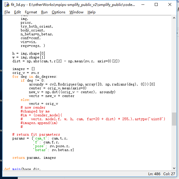
里面的params参数,也就是输出到.pkl文件的内容,包含四个属性:cam_t、f、pose、betas,分别是相机位置、焦距、姿势和形状参数,前两个暂时先无视,先把后两个比较重要的参数弄好。
用cpickle(python2)看看这两个参数:
with open(img_path,"r") as readFile:
    a=pickle.load(readFile)
    with open(out_path, 'w') as outf:
        print >> outf,a['cam_t'],
        print >> outf,a['f'],
        print >> outf,a['pose']
        print >> outf,a['betas']
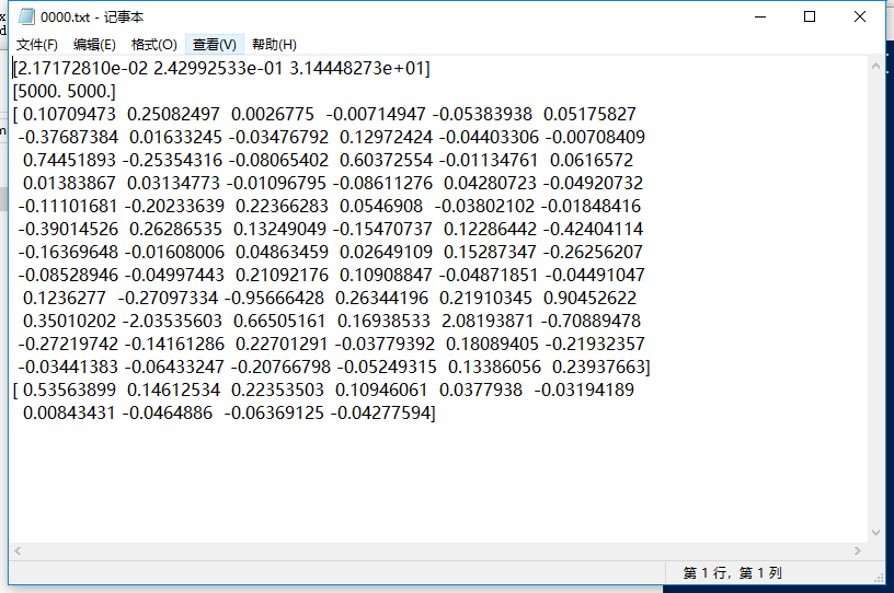 可以发现pose有72个参数,shape有10个参数,想一下smpl刚好有23个关节点+1([SMPL: A Skinned Multi-Person Linear Model](http://files.is.tue.mpg.de/black/papers/SMPL2015.pdf)里是这么说的,虽然我一直想把它当成24个关节点),并且在unity版本的smpl中的SMPLModifyBones.cs脚本里有这一段代码:
_boneNameToJointIndex = new Dictionary<string, int>();

_boneNameToJointIndex.Add("Pelvis", 0);
_boneNameToJointIndex.Add("L_Hip", 1);
_boneNameToJointIndex.Add("R_Hip", 2);
_boneNameToJointIndex.Add("Spine1", 3);
_boneNameToJointIndex.Add("L_Knee", 4);
_boneNameToJointIndex.Add("R_Knee", 5);
_boneNameToJointIndex.Add("Spine2", 6);
_boneNameToJointIndex.Add("L_Ankle", 7);
_boneNameToJointIndex.Add("R_Ankle", 8);
_boneNameToJointIndex.Add("Spine3", 9);
_boneNameToJointIndex.Add("L_Foot", 10);
_boneNameToJointIndex.Add("R_Foot", 11);
_boneNameToJointIndex.Add("Neck", 12);
_boneNameToJointIndex.Add("L_Collar", 13);
_boneNameToJointIndex.Add("R_Collar", 14);
_boneNameToJointIndex.Add("Head", 15);
_boneNameToJointIndex.Add("L_Shoulder", 16);
_boneNameToJointIndex.Add("R_Shoulder", 17);
_boneNameToJointIndex.Add("L_Elbow", 18);
_boneNameToJointIndex.Add("R_Elbow", 19);
_boneNameToJointIndex.Add("L_Wrist", 20);
_boneNameToJointIndex.Add("R_Wrist", 21);
_boneNameToJointIndex.Add("L_Hand", 22);
_boneNameToJointIndex.Add("R_Hand", 23);
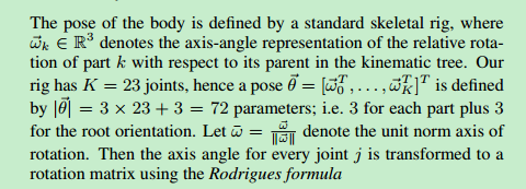
也就是说姿势中每连续的三个值代表一个结点的旋转角,而这个旋转角是localRotation,相对于它父亲的旋转角,SMPL: A Skinned Multi-Person Linear Model这篇文章里也有提及:
那么只需要按照这个顺序将pose参数导入到unity的smpl模型里就行了吧。我按照SMPLModifyBones.cs的updateBoneAngles函数仿写了以下代码看看效果:
public void SetParam(GameObject model,List<float> poseParam, List<float> shapeParam)//设置pose和shape参数
{
    var smr = model.GetComponent<SkinnedMeshRenderer>();
    var _bones = smr.bones;
    var _boneNamePrefix = "";


    foreach (Transform bone in _bones)
    {
        if (bone.name.EndsWith("root"))
        {
            int index = bone.name.IndexOf("root");
            _boneNamePrefix = bone.name.Substring(0, index);
            break;
        }
    }
    foreach (var bone in _bones)
    {
        string boneName = bone.name;
        boneName = boneName.Replace(_boneNamePrefix, "");
        int id;
        if (_boneNameToJointIndex.TryGetValue(boneName,out id))
        {
            bone.transform.localRotation = Quaternion.Euler(new Vector3(poseParam[id * 3], poseParam[id * 3 + 1], poseParam[id * 3 + 2]));
            //bone.transform.rotation = Quaternion.Euler(new Vector3(poseParam[id * 3], poseParam[id * 3 + 1], poseParam[id * 3 + 2]));
        }

    }
    float _shapeBlendsScale = 5.0f;
    for (int i = 0; i < 10; i++)
    {
        float pos, neg;
        float beta = shapeParam[i] / _shapeBlendsScale;

        if (beta >= 0)
        {
            pos = beta;
            neg = 0.0f;
        }
        else
        {
            pos = 0.0f;
            neg = -beta;
        }

        smr.SetBlendShapeWeight(i * 2 + 0, pos * 100.0f); // map [0, 1] space to [0, 100]
        smr.SetBlendShapeWeight(i * 2 + 1, neg * 100.0f); // map [0, 1] space to [0, 100]
    }
}
对于下面这张图,明显不对:

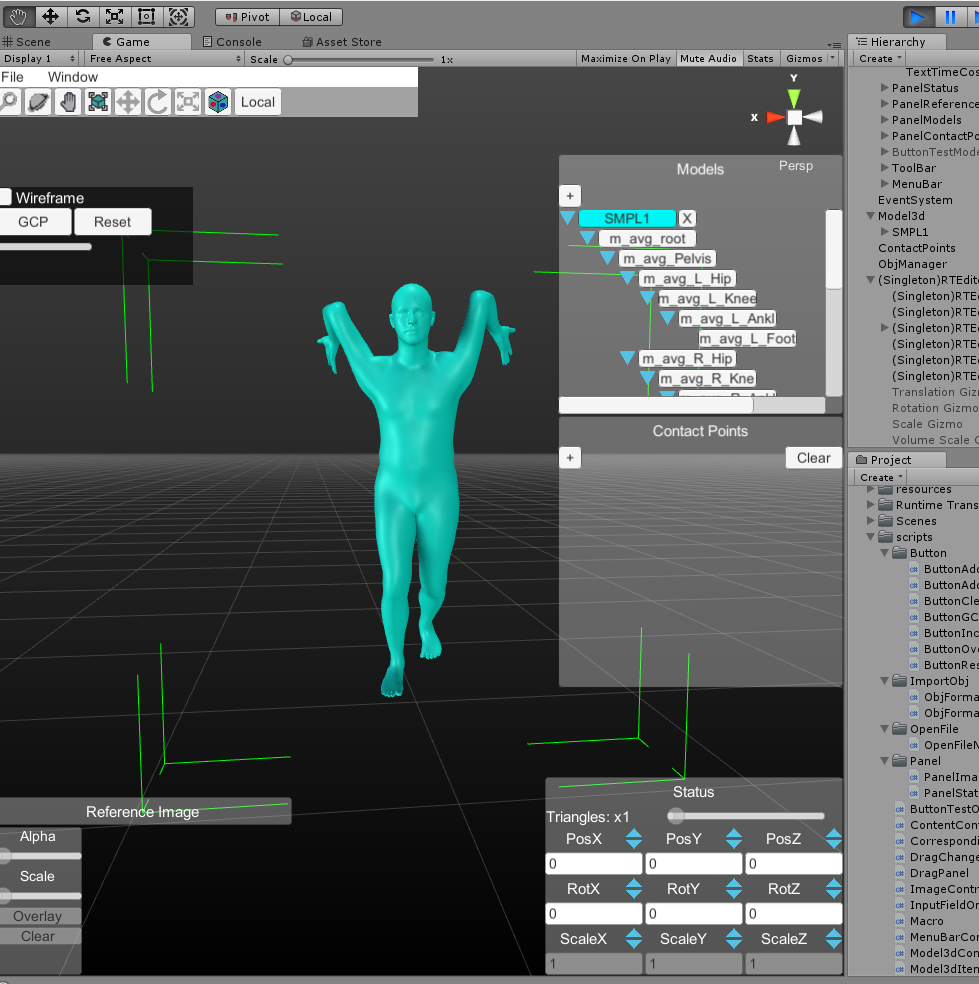
smpl_python版的生成效果如下,就是个obj文件我直接导入进去了,想获得obj文件就改一下python版的smpl文件夹里的hello_smpl.py中的pose和shape即可。
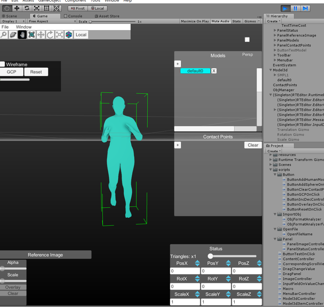
但是smpl的python代码里或者根据图像生成人物模型的源代码里压根没有类似的关于关节点的定义。
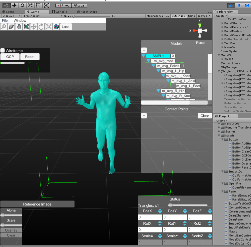
瞎试了半天,最后发现如果只看脚的话貌似左右脚的姿势刚好反了,于是我就把代码里的L和R互换位置看看:
_boneNameToJointIndex.Add("Pelvis", 0);
_boneNameToJointIndex.Add("R_Hip", 1);
_boneNameToJointIndex.Add("L_Hip", 2);
_boneNameToJointIndex.Add("Spine1", 3);
_boneNameToJointIndex.Add("R_Knee", 4);
_boneNameToJointIndex.Add("L_Knee", 5);
_boneNameToJointIndex.Add("Spine2", 6);
_boneNameToJointIndex.Add("R_Ankle", 7);
_boneNameToJointIndex.Add("L_Ankle", 8);
_boneNameToJointIndex.Add("Spine3", 9);
_boneNameToJointIndex.Add("R_Foot", 10);
_boneNameToJointIndex.Add("L_Foot", 11);
_boneNameToJointIndex.Add("Neck", 12);
_boneNameToJointIndex.Add("R_Collar", 13);
_boneNameToJointIndex.Add("L_Collar", 14);
_boneNameToJointIndex.Add("Head", 15);
_boneNameToJointIndex.Add("R_Shoulder", 16);
_boneNameToJointIndex.Add("L_Shoulder", 17);
_boneNameToJointIndex.Add("R_Elbow", 18);
_boneNameToJointIndex.Add("L_Elbow", 19);
_boneNameToJointIndex.Add("R_Wrist", 20);
_boneNameToJointIndex.Add("L_Wrist", 21);
_boneNameToJointIndex.Add("R_Hand", 22);
_boneNameToJointIndex.Add("L_Hand", 23);
看上去正常了一点,虽然还有点差距,但是对于用来做初始化而言感觉差不多了,之后就手动调各个关节的旋转角度即可。
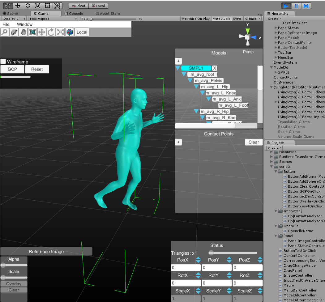
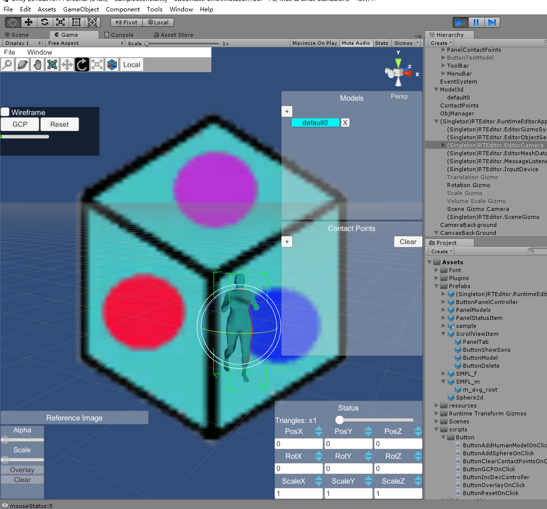
然后老师还说把人和物体交互的图像作为背景能更加方便用户标注,于是我查了一下发现可以用这个方法Unity项目使用静态图片做背景。效果如下:
