
FOTA-车端自动化测试方案设计(2)
接上篇,Capl编程详细实现,软件环境CANoe 11.0
1)Simulation Setup
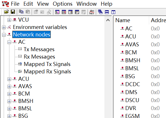
首先创建一个.DBC文件,然后新建待仿真的空节点,如下图,只有节点名称无任何信号。然后加载到Setup
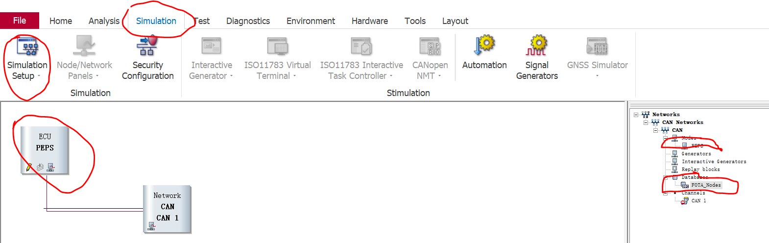
插入新节点,选择Insert Network Node, 然后右击新建的节点配置该节点属性。
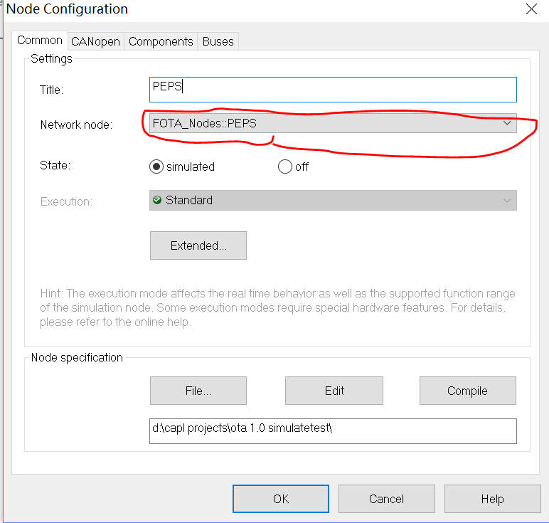
选择DBC中创建的对应节点名(此处很有用)
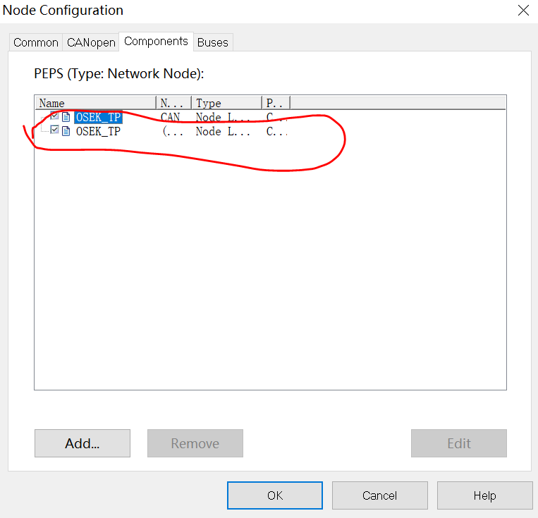
设置节点属性为OSEK_TP节点(添加osek_tp.dll即可,在canoe安装目录下查找,通常是 "C:\Program Files\Vector CANoe 11.0\Exec32")
创建完成的Simulation Setup如下图: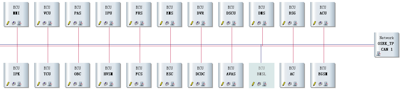
2)代码部分
此处选择GW(网关)节点作为样例讲解。其中涉及的环境变量和系统变量在代码中出现时再做说明
a. 实现ECU应用层行为仿真


1 /*@!Encoding:936*/
  2 includes
  3 {
  4   #include "GenericNode.cin"     //此处是一个造好的轮子,可见canoe提供的\OSEK_TP_MultiChannel  Demo
  5 }
  6
  7 variables
  8 {
  9   msTimer PhysRespTimer;  //物理寻址应答定时器
 10   msTimer FuncRespTimer;  //功能寻址应答定时器
 11   msTimer GWMessageTimer;    //ECU外发消息定时器,周期性的往总线发报文
 12   message 0x111 GW_message;    //此处是随便举例的报文,假设GW的tx报文就是id=0x111
 13   message 0x222 NWM_message;  //监控唤醒状态
 14   const int cycPepsTime = 100;    //100ms周期
 15 }
 16
 17 //每100ms发送一帧gw报文到总线,ecu信号仿真
 18 on timer GWMessageTimer
 19 {
 20   output(GW_message);
 21   setTimer(GWMessageTimer, cycPepsTime);
 22 }
 23
 24 //模拟按键弹起,物理寻址
 25 on timer PhysRespTimer
 26 {
 27     //注意此处的系统变量格式, ECUName::链路名::变量名, 本篇章节一介绍的在setup处建立节点时,要求配置选择数据库的节点名将在此处生效
 28   @sysvar::GW::Conn1::sysSendData = 0;
 29 }
 30
 31 //模拟按键弹起,功能寻址
 32 on timer FuncRespTimer
 33 {
 34   @sysvar::GW::Conn2::sysSendData = 0;  //注意此处链路名与上一函数不一样,区分物理寻址和功能寻址主要体现在这里
 35 }
 36 //监控一个环境变量,整车电源模式。 备注:环境变量可在DBC中创建
 37 on envVar PEPS_PwrMode
 38 {
 39   varPowerMode = getValue(PEPS_PwrMode); //先略过此变量的定义位置,全局变量记录电源状态
 40   GW_message.PEPS_PowerMode = varPowerMode;
 41   if(varPowerMode==2)
 42   {
 43     BCM_ATWS = 2;  //车身安全锁报警状态变量,略过定义处
 44   }
 45   if(varPowerMode == 3)//休眠
 46   {
 47     InactiveGW();
 48   }
 49   else
 50   {
 51     ActiveGW();
 52   }
 53 }
 54
 55 //模拟按键按下,物理寻址
 56 void diagPhysRespMessage()
 57 {
 58   if(IsResponse){
 59   @sysvar::GW::Conn1::sysSendData = 1;
 60   setTimer(PhysRespTimer, N_As);
 61   }
 62 }
 63
 64 //模拟按键按下,功能寻址
 65 void diagFuncRespMessage()
 66 {
 67   if(IsResponse){
 68   @sysvar::GW::Conn2::sysSendData = 1;
 69   setTimer(FuncRespTimer, N_As);
 70   }
 71 }
 72
 73 on message NWM_message
 74 {
 75   if(IsBUSActive == 0)
 76   {
 77     GW_message.PEPS_PowerMode = 0;
 78     ActiveGW();  //设备被唤醒,升级定时器触发后 激活信号
 79   }
 80 }
 81
 82 //处理来自诊断仪的物理寻址访问GW请求
 83 on message 0x701   //此处是捏造的物理寻址诊断ID,根据产品实际的来变更
 84 {
 85   diagReqMsg=this;
 86   writeDbgLevel(level_1, "---physical diagnostic request, id = 0x%x", diagReqMsg.id);
 87   SetValue(); //获取当前应回复值
 88   diagParseReqMessage();      //解析请求内容
 89   diagPhysRespMessage();    //应答请求
 90
 91 }
 92
 93 //处理来自诊断仪的功能寻址访问GW请求
 94 on message 0x7EE    //此处是捏造的功能寻址诊断ID,根据产品实际的来变更
 95 {
 96   diagReqMsg=this;
 97   writeDbgLevel(level_1, "---functional diagnostic request, id = 0x%x", diagReqMsg.id);
 98   diagParseReqMessage();
 99   diagFuncRespMessage();
100 }
101
102 //初始化仿真的通信信号值
103 void InitGWValue()
104 {
105   putValue(PEPS_PwrMode, 0);
106   GW_message.PEPS_PowerModeValidity = 2;
107   GW_message.PEPS_RemoteControlState = 0;
108 }
109 //初始化数据
110 void InitValue()
111 {
112     //以下是从配置文件读取 GW接到诊断请求时的应答的数据
113   getProfileString("GW", gEntry_1, gDefautStr, cOEMInfo, gLenEntry_1, gFileName);
114   putValue(GWOEMNumber, cOEMInfo); //EPS OEM  NO.
115 }
116
117 //获取ECU的回复参数
118 void SetValue()
119 {
120   getValue(GWOEMNumber, cOEMInfo);
121 }
122
123 on start
124 {
125   InitGWValue();
126   ActiveGW();
127 }
128
129 //停止仿真通信报文
130 void InactiveGW()
131 {
132   cancelTimer(GWMessageTimer);
133   IsBUSActive = 0;
134 }
135
136 //仿真通信报文
137 void ActiveGW()
138 {
139   setTimer(GWMessageTimer, cycPepsTime);
140   IsBUSActive = 1;
141 }
142
143 on preStart
144 {
145   InitValue();
146 }
147
148 //获取实时更新的OEM版本号
149 on envVar GWOEMNumber
150 {
151   char dest[100];
152   getValue(GWOEMNumber, cOEMInfo);
153   snprintf(dest, elcount(dest), "\"%s\"", cOEMInfo);
154   writeProfileString("GW", gEntry_1, dest, gFileName);
155 }
156
157 //数据对外发送的统一变量,所有ECU发送数据时通过它外传
158 on envVar varDataToTransmit
159 {
160   getValue(varDataToTransmit, cEnvVarBuffer);
161 }
以上代码,实现了ECU的通信信号仿真,不同的ECU之间的差异在于信号数量不一样、物理请求与功能请求的应答的链路的ECUName不一致, 诊断ID不一致。其余逻辑上完全一致。所以说二次开发很简单,只需要复制代码后 修改此三处即可完成新节点的增加
b. 通用接口实现
 1 includes
 2 {
 3   #include "GenericConn1.cin"
 4   #include "GenericConn2.cin"  //造好的轮子  建立链路,分别实现物理寻址与功能寻址
 5   #include "Common.cin"   //通用接口封装在此处
 6 }
 7
 8 variables
 9 {
10   char gECU[10] = "%NODE_NAME%";  //此变量是获取当前通信节点的名称,此处与通信链路中的ECUName很自然的关联起来了
11   enum AddressModes { kNormal = 0,
12                       kExtendedBased = 1,
13                       kNormalFixed = 2,
14                       kMixed = 3,
15   //......略去下面很多代码
16 }
diagParseReqMessage()实现,解析总线上的诊断请求报文
  1 /***********************************************************
  2 * description  : 解析收到的报文
  3 * creation date: 2018/11/13
  4 * author       : XXX
  5 * revision date:
  6 * revision log :
  7 * modifier     :
  8 ***********************************************************/
  9 void diagParseReqMessage()
 10 {
 11   byte fBValue;
 12   byte hNibble; //高四位
 13   byte lNibble; //低四位
 14   byte sid = 0x0;
 15   byte reserveSid = 0x0; //针对多帧请求的服务有效,特别预留
 16
 17   int remainderBLen;     //剩余未传输字节
 18   int remainderFrameCnt=0;
 19   int consecutiveFrameCnt=0;
 20   //获取首字节信息
 21   fBValue = diagReqMsg.byte(0);
 22   writeDbgLevel(level_1, "---The First Byte: 0x%02x", fBValue);
 23   hNibble = (fBValue>>4) & 0xf;
 24   lNibble = fBValue & 0xf;
 25   //writeDbgLevel(level_1, "high 4 bits=%d, low 4 bits=%d", hNibble, lNibble);
 26   IsResponse= 0; //初始化时默认不发送应答,需要发送应答时置位1
 27   //解析高字节信息
 28   if(0x0 == hNibble) //单帧
 29   {
 30     SF_DL = lNibble;
 31     sid = diagReqMsg.byte(1);
 32     writeDbgLevel(level_1, "SF: SF_DL=%d, sid=0x%x", SF_DL, sid);
 33     if(0x2e==sid){//写入服务
 34       subServiceId = ((diagReqMsg.byte(2)<<8)&0xffff)+diagReqMsg.byte(3);
 35       writeDbgLevel(level_1, "---SF:sid=0x%02x, ssid=0x%x---", sid, subServiceId);
 36     }
 37     else if(0x31==sid) //擦写 05 71 01 FF 01 04 AA AA
 38     {
 39       checkSum = (diagReqMsg.byte(2)<<24) | (diagReqMsg.byte(3)<<16)
 40       |(diagReqMsg.byte(4)<<8) | diagReqMsg.byte(5);
 41        writeDbgLevel(level_1, "---SF:crc or flush, 0x%x---", checkSum);
 42     }
 43     diagProcessSFRequest(sid); //根据实际服务回复应答内容
 44   }
 45   else if(0x1 == hNibble) //多帧首帧
 46   {
 47     FF_DL = ((lNibble<<8)&0xfff) + diagReqMsg.byte(1);
 48     reserveSid = diagReqMsg.byte(2);
 49     remainderFrameCnt = 0; //回复0值
 50     consecutiveFrameCnt = 0;  //置0连续帧
 51     remainderBLen = (FF_DL - 6);
 52     writeDbgLevel(level_1, "---MF:sid=0x%02x", reserveSid);
 53     if(reserveSid==0x2e){
 54       subServiceId = ((diagReqMsg.byte(3)<<8)&0xffff)+diagReqMsg.byte(4);
 55       writeDbgLevel(level_1, "---MF:ssid=0x%x---", subServiceId);
 56     }
 57     else if(reserveSid==0x36) //经验, 将数据放置在左边,可避免少写=的异常
 58     {
 59       transferDataSN = diagReqMsg.byte(3);
 60       writeDbgLevel(level_1, "---MF:data sn=0x%x---", transferDataSN);
 61     }
 62     else if(reserveSid==0x31) //校验
 63     {
 64       checkSum = (diagReqMsg.byte(3)<<24) | (diagReqMsg.byte(4)<<16)
 65       |(diagReqMsg.byte(5)<<8) | diagReqMsg.byte(6);
 66       writeDbgLevel(level_1, "---MF:crc or flush, 0x%x---", checkSum);
 67       IsCRCDone = 1; //已校验过 刷写完成
 68     }
 69
 70     if(remainderBLen%7 == 0)
 71     {
 72       remainderFrameCnt = remainderBLen/7;
 73     }
 74     else
 75     {
 76       remainderFrameCnt = remainderBLen/7 + 1;
 77     }
 78     writeDbgLevel(level_1, "MF: FF_DL=%d,remainder frame count=%d", FF_DL, remainderFrameCnt);
 79   }
 80   else if(0x2 == hNibble) //连续帧
 81   {
 82     SN = lNibble;
 83     consecutiveFrameCnt += 1;
 84     writeDbgLevel(level_1, "CF: SN=%x, current count=%d", SN, consecutiveFrameCnt);
 85     sid = 0x0;
 86   }
 87   else if(0x3 == hNibble) //流控帧
 88   {
 89     FS = lNibble;
 90     BS = diagReqMsg.byte(1);
 91     STmin = diagReqMsg.byte(2);
 92     writeDbgLevel(level_1, "FC: FS=%d, BS=%d, ST min=%d", FS, BS, STmin);
 93     sid = 0x0;
 94   }
 95   else
 96   {
 97     writeDbgLevel(level_1, "error frame");
 98   }
 99
100   //响应多帧请求
101   if(remainderFrameCnt!=0)
102   {
103     if(remainderFrameCnt == consecutiveFrameCnt)
104     {
105       diagProcessMFRequest(reserveSid); //封装具体的应答逻辑,可以根据诊断协议获知
106       IsResponse= 1;
107       consecutiveFrameCnt = 0;
108     }
109   }
110 }
完成了车内ECU的仿真,启动CANoe后,仿真的ECU就可以验证TBOX的FOTA流程正确性啦。
--------------完结-------------------
以上只实现了正向刷写流程的验证,覆盖异常场景还需做更多的开发工作。
仿真测试极具灵活性与扩展性,测试时可以根据需求加入或移除节点。这非常便于在开发过程中持续集成的实施。
仿真测试对于构造异常场景的测试条件比实车上简单,非破坏性的且可重复的测试手段,测试数据和过程可控可追溯。

 浙公网安备 33010602011771号