【计网实验】三层交换机的配置
三层交换机的配置
实验环境
- 仿真平台:Cisco Packet Tracer 6.1
- 终端系统:Linux Ubuntu Mate 20.04
- 交换机:3560-24PS
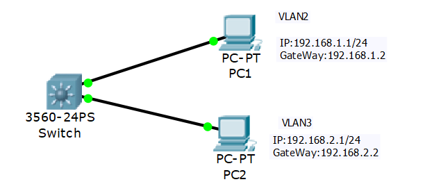
实验1:通过 vlan ip 做网关,实现不同 vlan 间的路由
网络拓扑
网络配置
- PC1:192.168.1.1/24,网关192.168.1.2
- PC2:192.168.2.1/24,网关192.168.2.2
实验步骤
1.配置交换机
Switch>en
Switch#vlan data
Switch(vlan)#vlan 2
VLAN 2 added:
    Name: VLAN0002
Switch(vlan)#vlan 3
VLAN 3 added:
    Name: VLAN0003
Switch(vlan)#exit

Switch#conf t
Enter configuration commands, one per line.  End with CNTL/Z.
Switch(config)#int f0/1
Switch(config-if)#switchport mode access
Switch(config-if)#switchport access vlan 2
Switch(config-if)#int f0/2
Switch(config-if)#switchport mode access
Switch(config-if)#switchport access vlan 3
Switch(config-if)#exit

Switch(config)#int vlan 2
Switch(config-if)#ip address 192.168.1.2 255.255.255.0
Switch(config-if)#no shutdown
Switch(config-if)#int vlan 3
Switch(config-if)#ip address 192.168.2.2 255.255.255.0
Switch(config-if)#no shutdown
Switch(config-if)#exit
Switch(config)#ip routing
Switch(config)#end
2.检查配置
VLAN配置:
Switch#show vlan

VLAN Name                             Status    Ports
---- -------------------------------- --------- -------------------------------
1    default                          active    Fa0/3, Fa0/4, Fa0/5, Fa0/6
                                                Fa0/7, Fa0/8, Fa0/9, Fa0/10
                                                Fa0/11, Fa0/12, Fa0/13, Fa0/14
                                                Fa0/15, Fa0/16, Fa0/17, Fa0/18
                                                Fa0/19, Fa0/20, Fa0/21, Fa0/22
                                                Fa0/23, Fa0/24, Gig0/1, Gig0/2
2    VLAN0002                         active    Fa0/1
3    VLAN0003                         active    Fa0/2
1002 fddi-default                     act/unsup
1003 token-ring-default               act/unsup
1004 fddinet-default                  act/unsup
1005 trnet-default                    act/unsup

VLAN Type  SAID       MTU   Parent RingNo BridgeNo Stp  BrdgMode Trans1 Trans2
---- ----- ---------- ----- ------ ------ -------- ---- -------- ------ ------
1    enet  100001     1500  -      -      -        -    -        0      0
2    enet  100002     1500  -      -      -        -    -        0      0
3    enet  100003     1500  -      -      -        -    -        0      0
1002 fddi  101002     1500  -      -      -        -    -        0      0
1003 tr    101003     1500  -      -      -        -    -        0      0
1004 fdnet 101004     1500  -      -      -        ieee -        0      0
1005 trnet 101005     1500  -      -      -        ibm  -        0      0

Remote SPAN VLANs
------------------------------------------------------------------------------


Primary Secondary Type              Ports
------- --------- ----------------- ------------------------------------------
路由配置:
Switch#show ip route
Codes: C - connected, S - static, I - IGRP, R - RIP, M - mobile, B - BGP
       D - EIGRP, EX - EIGRP external, O - OSPF, IA - OSPF inter area
       N1 - OSPF NSSA external type 1, N2 - OSPF NSSA external type 2
       E1 - OSPF external type 1, E2 - OSPF external type 2, E - EGP
       i - IS-IS, L1 - IS-IS level-1, L2 - IS-IS level-2, ia - IS-IS inter area
       * - candidate default, U - per-user static route, o - ODR
       P - periodic downloaded static route

Gateway of last resort is not set

C    192.168.1.0/24 is directly connected, Vlan2
C    192.168.2.0/24 is directly connected, Vlan3
通信测试
使用PC1来Ping PC2:
PC>ipconfig

FastEthernet0 Connection:(default port)

   Link-local IPv6 Address.........: FE80::201:96FF:FEB5:9EBD
   IP Address......................: 192.168.1.1
   Subnet Mask.....................: 255.255.255.0
   Default Gateway.................: 192.168.1.2

PC>ping 192.168.1.1

Pinging 192.168.1.1 with 32 bytes of data:

Reply from 192.168.1.1: bytes=32 time=5ms TTL=128
Reply from 192.168.1.1: bytes=32 time=0ms TTL=128
Reply from 192.168.1.1: bytes=32 time=1ms TTL=128
Reply from 192.168.1.1: bytes=32 time=2ms TTL=128

Ping statistics for 192.168.1.1:
    Packets: Sent = 4, Received = 4, Lost = 0 (0% loss),
Approximate round trip times in milli-seconds:
    Minimum = 0ms, Maximum = 5ms, Average = 2ms

PC>ping 192.168.1.2

Pinging 192.168.1.2 with 32 bytes of data:

Reply from 192.168.1.2: bytes=32 time=0ms TTL=255
Reply from 192.168.1.2: bytes=32 time=0ms TTL=255
Reply from 192.168.1.2: bytes=32 time=0ms TTL=255
Reply from 192.168.1.2: bytes=32 time=0ms TTL=255

Ping statistics for 192.168.1.2:
    Packets: Sent = 4, Received = 4, Lost = 0 (0% loss),
Approximate round trip times in milli-seconds:
    Minimum = 0ms, Maximum = 0ms, Average = 0ms

PC>ping 192.168.2.2

Pinging 192.168.2.2 with 32 bytes of data:

Reply from 192.168.2.2: bytes=32 time=1ms TTL=255
Reply from 192.168.2.2: bytes=32 time=0ms TTL=255
Reply from 192.168.2.2: bytes=32 time=0ms TTL=255
Reply from 192.168.2.2: bytes=32 time=0ms TTL=255

Ping statistics for 192.168.2.2:
    Packets: Sent = 4, Received = 4, Lost = 0 (0% loss),
Approximate round trip times in milli-seconds:
    Minimum = 0ms, Maximum = 1ms, Average = 0ms

PC>ping 192.168.2.1

Pinging 192.168.2.1 with 32 bytes of data:

Reply from 192.168.2.1: bytes=32 time=1ms TTL=127
Reply from 192.168.2.1: bytes=32 time=0ms TTL=127
Reply from 192.168.2.1: bytes=32 time=0ms TTL=127
Reply from 192.168.2.1: bytes=32 time=0ms TTL=127

Ping statistics for 192.168.2.1:
    Packets: Sent = 4, Received = 4, Lost = 0 (0% loss),
Approximate round trip times in milli-seconds:
    Minimum = 0ms, Maximum = 1ms, Average = 0ms
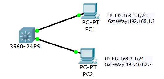
实验2:通过设置端口的三层工作模式实现不同网络的路由
网络拓扑
实验步骤
Switch>en
Switch#conf t
Switch(config)#int f0/1
Switch(config-if)#no switchport
Switch(config-if)#ip address 192.168.1.2 255.255.255.0
Switch(config-if)#int f0/2
Switch(config-if)#no switchport
Switch(config-if)#ip address 192.168.2.2 255.255.255.0
Switch(config-if)#exit
Switch(config)#ip routing
Switch(config)#end
Switch#wr
Building configuration...
[OK]

Switch#show ip route
Codes: C - connected, S - static, I - IGRP, R - RIP, M - mobile, B - BGP
       D - EIGRP, EX - EIGRP external, O - OSPF, IA - OSPF inter area
       N1 - OSPF NSSA external type 1, N2 - OSPF NSSA external type 2
       E1 - OSPF external type 1, E2 - OSPF external type 2, E - EGP
       i - IS-IS, L1 - IS-IS level-1, L2 - IS-IS level-2, ia - IS-IS inter area
       * - candidate default, U - per-user static route, o - ODR
       P - periodic downloaded static route

Gateway of last resort is not set

C    192.168.1.0/24 is directly connected, FastEthernet0/1
C    192.168.2.0/24 is directly connected, FastEthernet0/2
用这种方法实现不同网段的互联其实就是把三层交换机当做普通路由器使用,连接的两个端口分别配置不同的局域网,通过路由器连接两个不同的局域网。


【推荐】国内首个AI IDE,深度理解中文开发场景,立即下载体验Trae
【推荐】编程新体验,更懂你的AI,立即体验豆包MarsCode编程助手
【推荐】抖音旗下AI助手豆包,你的智能百科全书,全免费不限次数
【推荐】轻量又高性能的 SSH 工具 IShell:AI 加持,快人一步
· winform 绘制太阳,地球,月球 运作规律
· 超详细:普通电脑也行Windows部署deepseek R1训练数据并当服务器共享给他人
· TypeScript + Deepseek 打造卜卦网站:技术与玄学的结合
· AI 智能体引爆开源社区「GitHub 热点速览」
· 写一个简单的SQL生成工具