韦东山2440-学习笔记-framebuffer
1. framebuffer框架简述
1.1 init
init完成主设备号申请,cdev创建并加入系统,设置了fops,但这个fops只是虚函数
fbmem_init
  register_chrdev
1.2 open
fb_open
  fbidx = iminor(inode);
  info = registered_fb[fbidx];
  info->fbops->fb_open(info,1);
可见 registered_fb[] 记录了真正的驱动
1.3 read
fb_read
  fbidx = iminor(inode);
  info = registered_fb[fbidx];
  if (info->fbops->fb_read)
    return info->fbops->fb_read(info, buf, count, ppos);
  src = (u32 __iomem *) (info->screen_base + p);
  while (count) {
    *dst++ = fb_readl(src++);
  }
如果具体的驱动没有实现read,则使用通用 的read,即直接拷贝frame_buffer的数据
1.4 注册 framebuffer
由上分析可知,fbmem只是中间层,具体的驱动在 registered_fb[]。
谁写 registered_fb[] ?
register_framebuffer(struct fb_info *fb_info)
  fb_info->dev = device_create(fb_class, fb_info->device,
                       MKDEV(FB_MAJOR, i), "fb%d", i);  // 添加设备,就会创建设备节点/dev/fb0 /dev/fdb1 之类
  registered_fb[i] = fb_info;  // 注册到  registered_fb[] ,应用层就可以调用
所以驱动的写步骤是:
- 分配fb_info
- 设置fb_info
- 注册register_framebuffer
2. LCD硬件知识
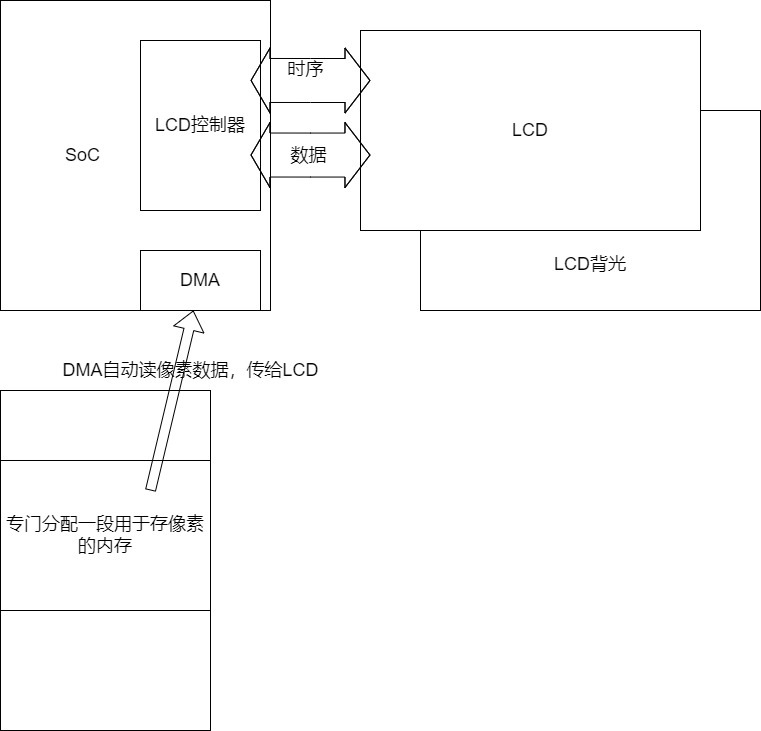
涉及的硬件有:
LCD控制器:通过SoC寄存器设置,让LCD控制器满足LCD能支持的时序,等
LCD:只需要设置引脚保证供电
LCD背光:需要设置引脚保证供电
DMA:Linux有模块会设置,写LCD驱动不需要管
GPIO控制器:
2.2 引脚
首先看LCD的手册
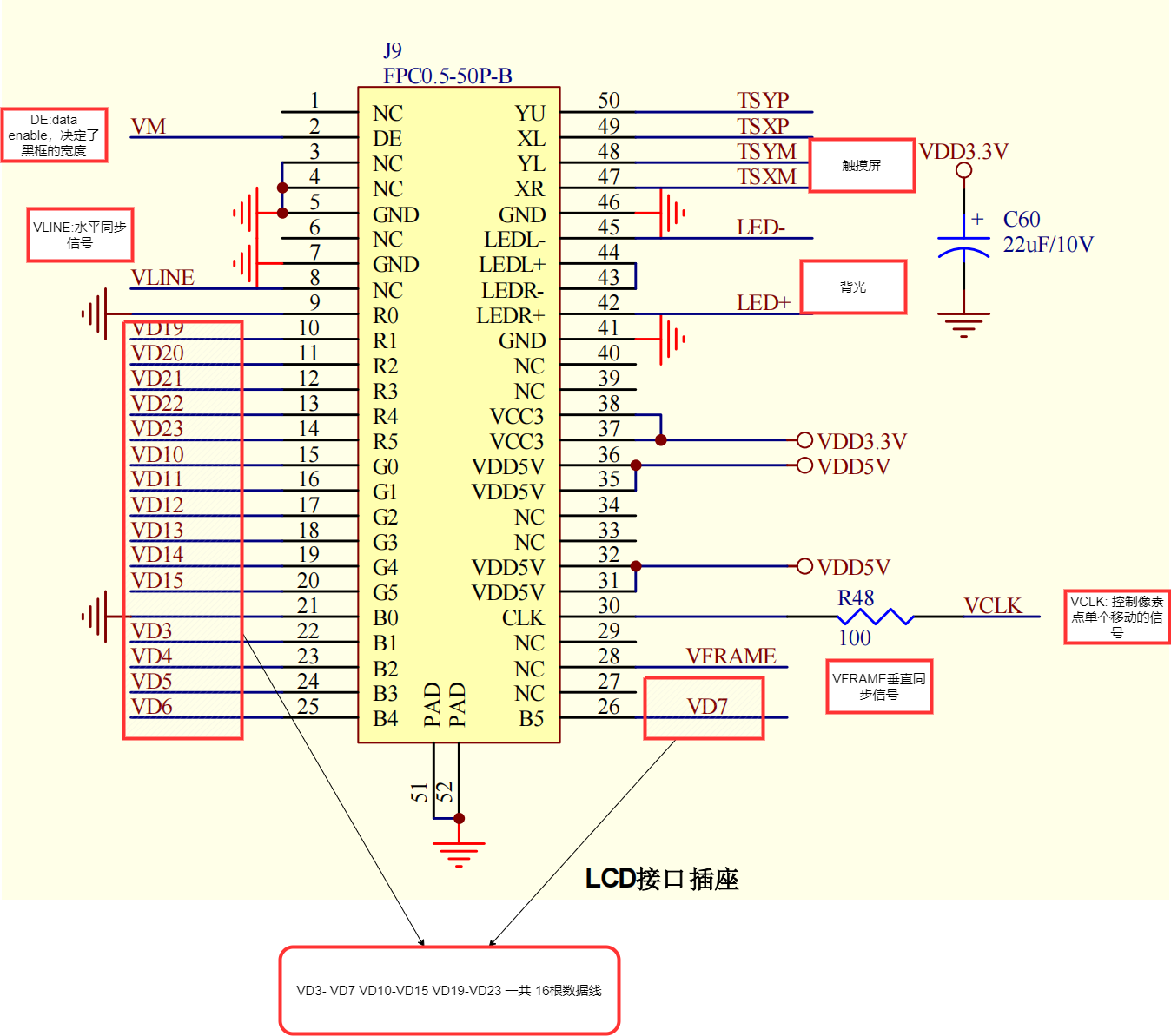
- 所有引脚都需要设置为LCD相关
- SoC使用了 16 根数据线,说明一个像素点最多能用16bit描述
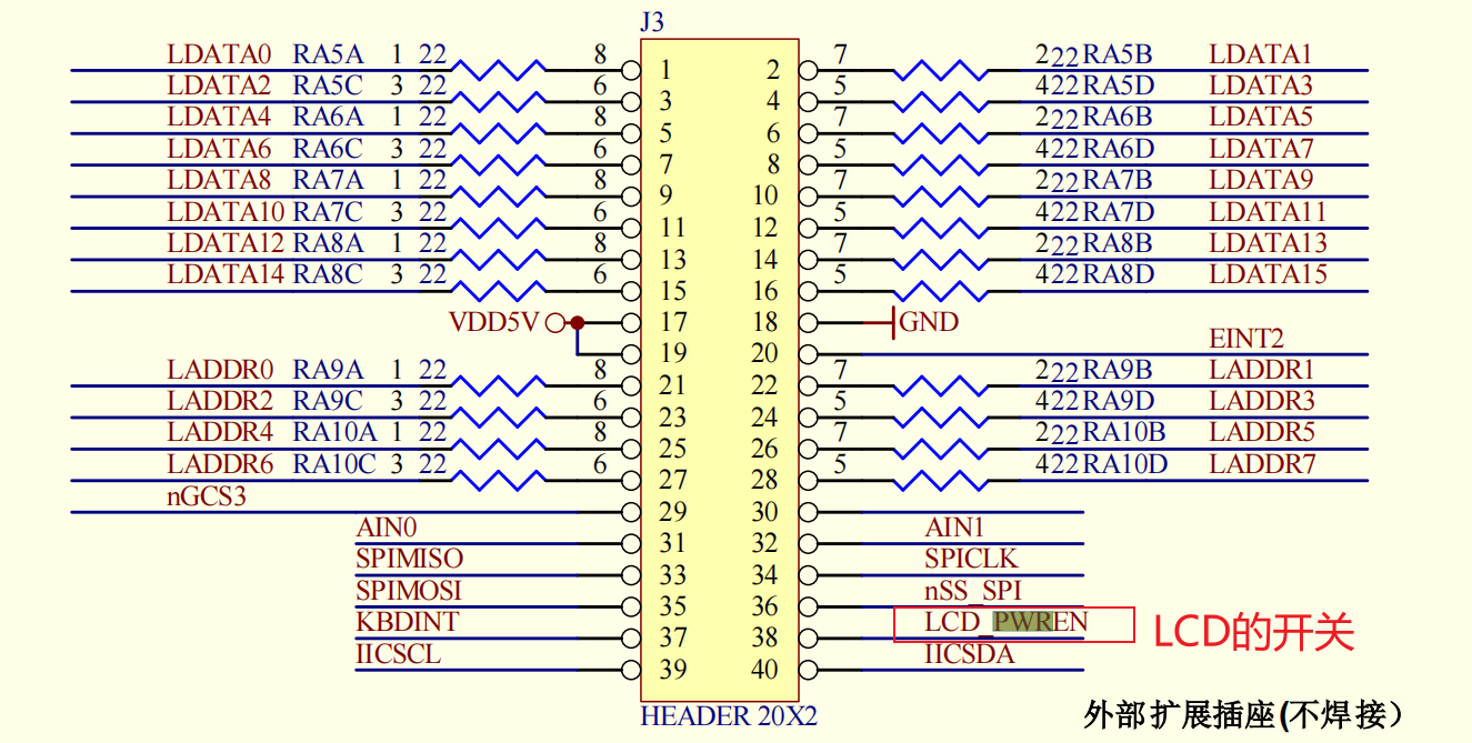
背光的开关

LCD的开关
2.1 时序
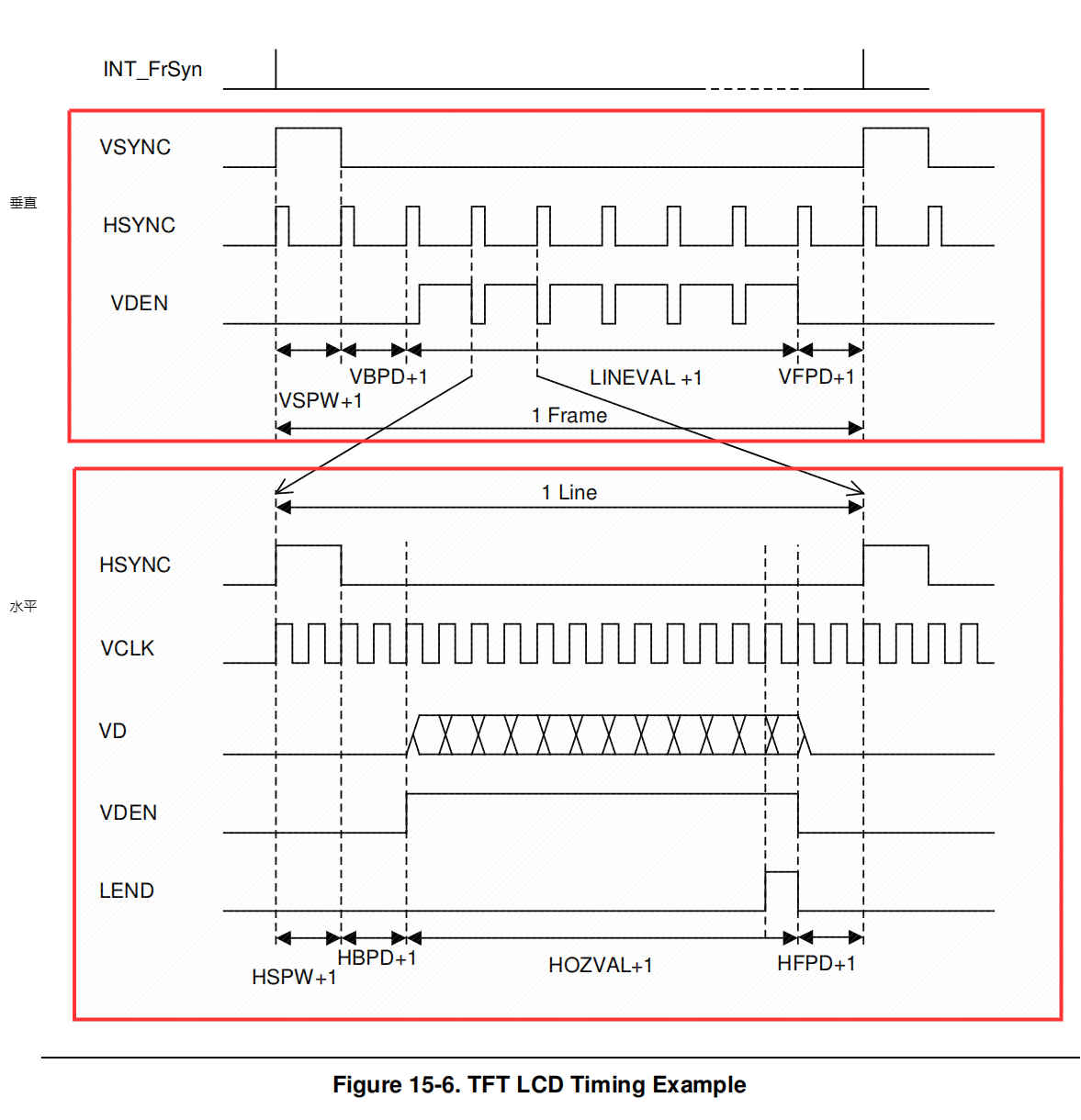
LCD 控制的时序
LCD的时序
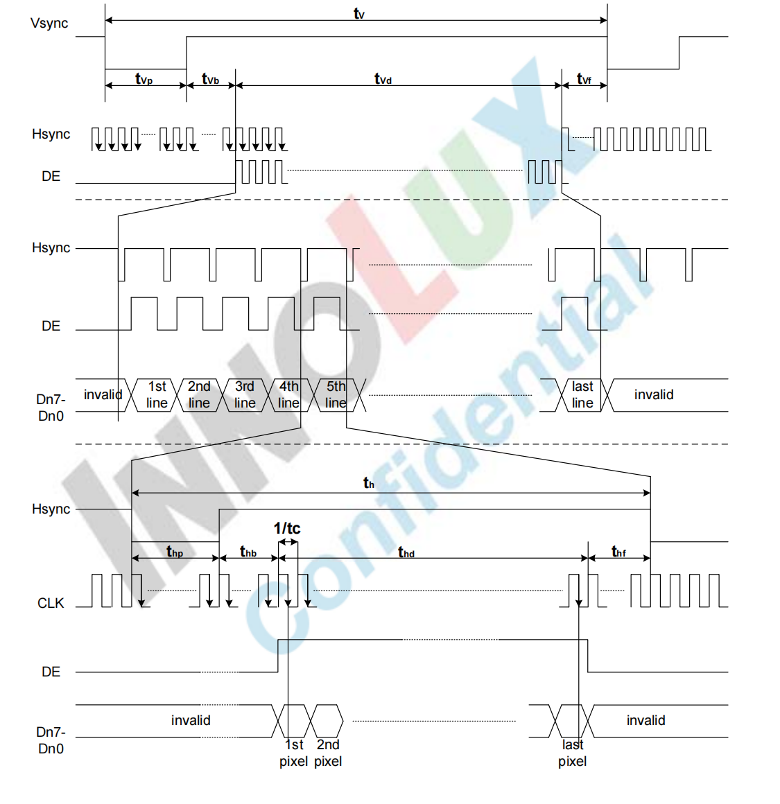
需要将LCD的时序和LCD控制器的时序结合看,找到两者关系,设置LCD控制器的时序让其满足LCD的时序。
LCD需要那种时序值,根据LCD手册
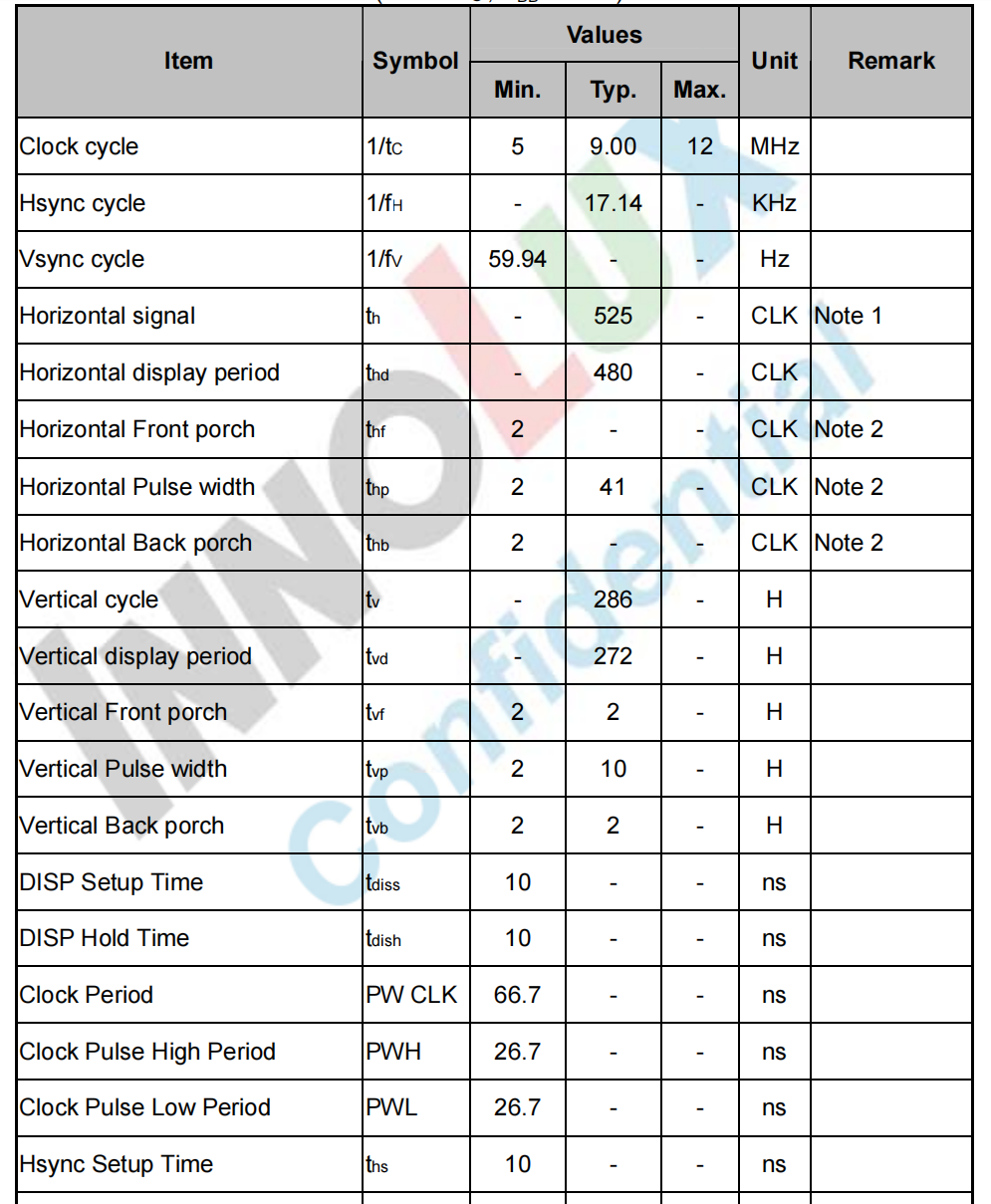
2.3 极性
还是结合LCD和控制器的时序图,可知极性是否需翻转
2.4 像素格式
根据LCD芯片手册知道,LCD支持32bpp,但是根据电路图,可知只是用了16位,所以最多使用 16bpp。
像素数据在内存的存放格式,只与LCD控制器有关,所以看SoC手册。
发现16bpp支持两种排布,可按照需要选择一种,并设置相关寄存器,
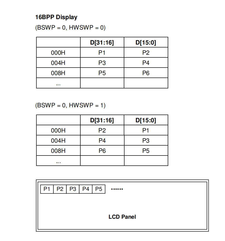
2. 代码
LCD寄存器设置太多,具体描述都放到代码中
#include <linux/module.h>
#include <linux/dma-mapping.h>
#include <linux/fb.h>
#include <linux/bitops.h>
#include <linux/input.h>
#include <linux/spinlock.h>
#include <asm/atomic.h>
#include <linux/poll.h>
#include <linux/interrupt.h>
#include <linux/device.h>
#include <linux/cdev.h>
#include <linux/kernel.h>
#include <linux/fs.h>
#include <linux/init.h>
#include <linux/delay.h>
#include <linux/irq.h>
#include <asm/uaccess.h>
#include <asm/irq.h>
#include <asm-arm/irq.h>
#include <asm/io.h>
#include <asm/arch/regs-gpio.h>
#include <asm/hardware.h>

struct s3c_lcd_regs {
        unsigned long lcdcon1;
        unsigned long lcdcon2;
        unsigned long lcdcon3;
        unsigned long lcdcon4;
        unsigned long lcdcon5;
        unsigned long lcdsaddr1;
        unsigned long lcdsaddr2;
        unsigned long lcdsaddr3;
        unsigned long redlut;
        unsigned long greenlut;
        unsigned long bluelut;

        unsigned long reserve[9];

        unsigned long dithmode;
        unsigned long tpal;
        unsigned long lcdintpnd;
        unsigned long lcdsrcpnd;
        unsigned long lcdintmsk;
        unsigned long tconsel;
};

static struct fb_info *s3c_info;

volatile static unsigned long *gpccon;
volatile static unsigned long *gpdcon;
volatile static unsigned long *gpbcon;
volatile static unsigned long *gpbdat;
volatile static unsigned long *gpgcon;

struct s3c_lcd_regs *s3c_lcd_regs;

static unsigned int pseudo_palette[16];

static int s3c_setcolreg(u_int regno, u_int red, u_int green, u_int blue,
                   u_int trans, struct fb_info *info);


// 显存操作函数,使用其他模块的实现
static struct fb_ops s3c_ops = {
        .owner          = THIS_MODULE,
        .fb_setcolreg = s3c_setcolreg,
        .fb_fillrect    = cfb_fillrect,
        .fb_copyarea    = cfb_copyarea,
        .fb_imageblit   = cfb_imageblit,
};

static inline unsigned int
chan_to_field(unsigned int chan, const struct fb_bitfield *bf)
{
        chan &= 0xffff;
        chan >>= 16 - bf->length;
        return chan << bf->offset;
}

// 设置调色板
static int
s3c_setcolreg(u_int regno, u_int red, u_int green, u_int blue,
                   u_int trans, struct fb_info *info)
{
        unsigned int val;

        if (regno > 16)
                return -1;
        //pal = fbi->fb.pseudo_palette;

        val  = chan_to_field(red, &info->var.red);
        val |= chan_to_field(green, &info->var.green);
        val |= chan_to_field(blue, &info->var.blue);

        pseudo_palette[regno] = val;

        return 0;
}

#define SCREEN_W        480
#define SCREEN_H        272


static int __init
lcd_dev_init(void)
{
        // 1. 分配fb_info
        s3c_info = framebuffer_alloc(0, NULL);

        // 2. 设置fb_info
        // 2.1 设置固定参数
        strcpy(s3c_info->fix.id, "mylcd");
        s3c_info->fix.smem_len = SCREEN_W * SCREEN_H * 2;        // framebuffer 的总长度, 一共 480 * 272 个像素,每个像素使用 16bit表示,也就是 2Byte
        s3c_info->fix.type_aux = FB_TYPE_PACKED_PIXELS; // 确定像素点的存储方式,存储方式决定了存储和传输速度和图像处理性能消耗, 优化时考虑,所以使用默认值
        s3c_info->fix.visual = FB_VISUAL_TRUECOLOR; // 确定可视化类型定义,使用真彩色
        s3c_info->fix.xpanstep = 0; // 表示每次水平滚动时,显示器位置相对于显存位置的增量,可以设为水平像素行占用多少字节,以实现显存相对显示器的滚动,不使用时设置为0
        s3c_info->fix.ypanstep = 0; // 同上
        s3c_info->fix.line_length = 2* SCREEN_W; // 一行像素占用的字节数, 使用 16bpp 所以一个像素占据2Byte,分辨率为 480*272,所以一行占用字节为 2*272
        //s3c_info->fix.mmio_start = ; // 显卡的显存基地址,是物理地址,没有显卡所以不设置
        //s3c_info->fix.mmio_len = ; //
        //s3c_info->fix.accel = ; // 像驱动表明我们使用的硬件

        // 2.2 设置可变参数
        s3c_info->var.xres = SCREEN_W; // 硬件分辨率
        s3c_info->var.yres = SCREEN_H;
        s3c_info->var.xres_virtual = SCREEN_W; // 在虚拟内存空间中,一行有多少像素, xres_virtual 可以大于 xres(如实现屏幕缩放和滚动) 也可以小于 xres (实现分页和双缓冲)
        s3c_info->var.yres_virtual = SCREEN_H;
        s3c_info->var.xoffset = 0; // 表示在显存中的显示区域, 其实位置为 (xoffset, yoffset), 结束位置为 (xoffset + xres, yoffset + yres)
        s3c_info->var.yoffset = 0;
        s3c_info->var.bits_per_pixel = 16; // 也就是 bpp,我们使用16bpp即一个像素占用16位
        s3c_info->var.grayscale = 0; // 是否为灰度模式,非0,为灰度模式,显示黑白,0为彩色模式

        // 颜色分量在像素中的位数和位置
        // [5:6:5]
        // [11:5:0]
        s3c_info->var.red.offset = 11;
        s3c_info->var.red.length = 5;
        s3c_info->var.red.msb_right = 0;

        s3c_info->var.green.offset = 5;
        s3c_info->var.green.length = 6;
        s3c_info->var.green.msb_right = 0;

        s3c_info->var.blue.offset = 0;
        s3c_info->var.blue.length = 5;
        s3c_info->var.blue.msb_right = 0;

        //s3c_info->var.transp = ; // 透明度分量

        s3c_info->var.nonstd = 0; // 是否是非标准格式RGB,不是,我们使用 RGB5:6:5,是标准的

        /*
         * FB_ACTIVATE_NOW:立即激活新的帧缓冲区,不等待垂直同步信号。这种方式可以实现无闪烁的页面刷新,但可能会导致图像出现撕裂现象。
        * FB_ACTIVATE_FORCE:强制激活新的帧缓冲区,无论是否已经接收到垂直同步信号。这种方式可以避免图像出现撕裂现象,但可能会导致屏幕闪烁。
        * FB_ACTIVATE_VBL:在下一次垂直同步信号到来时激活新的帧缓冲区。这种方式可以保证图像不会出现撕裂现象,但可能会导致页面刷新速度较慢。
        */
//      s3c_info->var.activate = FB_ACTIVATE_NOW; // 控制显示设备的激活状态
        s3c_info->var.activate = FB_ACTIVATE_VBL; // 控制显示设备的激活状态

        // MARK
        s3c_info->var.height = SCREEN_H; // 帧缓冲区高度
        s3c_info->var.width = SCREEN_W;

        //s3c_info->var. timing 部分设置了也没用

        // 2.3 设置操作函数
        s3c_info->fbops = &s3c_ops;

        // 2.4 其他设置
        //s3c_info->screen_base = ;  // 显存的虚拟地址
        s3c_info->screen_size = SCREEN_W * SCREEN_H * 2;
        s3c_info->pseudo_palette = pseudo_palette;


        // 3. 硬件相关
        // 3.1 设置GPIO支持LCD
        // VD3-VD7   GPC11-GPC15
        // VD15-VD23 GPD7-GPD15

        gpccon = ioremap(0x56000020, sizeof(unsigned long));
        gpdcon = ioremap(0x56000030, sizeof(unsigned long));

        *gpccon &= ~((3 << 11*2) | (3 << 12*2) | (3 << 13*2) | (3 << 14*2) | (3 << 15*2));
        *gpccon |= (2 << 11*2) | (2 << 12*2) | (2 << 13*2) | (2 << 14*2) | (2 << 15*2);


        *gpdcon &= ~(((3 << 7*2) | (3 << 8*2) | (3 << 9*2) | (3 << 10*2) |
                                                (3 << 11*2) | (3 << 12*2) | (3 << 13*2) | (3 << 14*2) |
                                                (3 << 15 *2)));
        *gpdcon |= ((2 << 7*2) | (2 << 8*2) | (2 << 9*2) | (2 << 10*2) |
                                                (2 << 11*2) | (2 << 12*2) | (2 << 13*2) | (2 << 14*2) |
                                                (2 << 15 *2));

        // 像素点移动信号       VCLK            GPC1
        *gpccon &= ~(3 << 1*2);
        *gpccon |= (2 << 1*2);

        // 行同步信号           VLINE           GPC2
        *gpccon &= ~(3 << 2*2);
        *gpccon |= (2 << 2*2);

        // 数据有效信号         VM                      GPC4
        *gpccon &= ~(3 << 4*2);
        *gpccon |= (2 << 4*2);

        // 垂直同步信号         VFRAME          GPC3
        *gpccon &= ~(3 << 3*2);
        *gpccon |= (2 << 3*2);

        // 背光电路                     KEYBOARD        GPB0
        gpbcon = ioremap(0x56000010, sizeof(unsigned long) * 2);
        gpbdat = gpbcon + 1;

        // 设置为输出模式,输出低电平,关闭LCD控制器
        *gpbcon &= ~(3 << 0);
        *gpbcon |= (1 << 0);

        *gpbdat &= ~(1 << 0);

        // LCD供电                      LCD_PWREN       GPG4
        gpgcon = ioremap(0x56000060, sizeof(unsigned long ));

        // 设置为LCD供电模式
        *gpgcon |= (3 << 4*2);

        // 3.2 设置lcd 控制器
        s3c_lcd_regs = ioremap(0X4D000000, sizeof(*s3c_lcd_regs));

        /*
         * [27:18]                 read only
         * [17:8]  : 0b101         决定VCLK速度
         *                                  VCLK = HCLK / [ (CLKVAL +1) * 2]
         *                                  clkval = hclk/(vclk*2) - 1
         *                                                 = 100/18 -1 = 4.5
         * [7]     : 0          决定VM的翻转速率 , 不懂 设置
         * [6:5]   : 0b11               显示模式
         * [4:1]   : 0b1100             bpp模式 16bpp for TFT
         * [0]     : 0b0                禁止LCD控制器
         */
        s3c_lcd_regs->lcdcon1 = 0x00000578;

        /*
         * 时序
         * [31:24] : 1      vpbd + 1 = 2(tvb)
         * [23:14] : 271    lineval + 1 = 272(tvd)
         * [13:6]  : 1      vfpd + 1 = 2(tvf)
         * [5:0]   : 9      VSPW + 1 = 10(tvp)
         */
        s3c_lcd_regs->lcdcon2 = (1 << 24) | (271 << 14) | (1 << 6) | (9 << 0) ;

        /*
         * 时序
         * [25:19] : 1       HBPD + 1 = 2(thb)
         * [18:8]  : 479     HOZVAL + 1 = 480(thd)
         * [7:0]   : 1       HFPD + 1 = 2(thf)
         *
         */
        s3c_lcd_regs->lcdcon3 = (1 << 19) | (479 << 8) | (1 << 0);

        /*
         * 时序
         * [15:8]            STN显示器设置,忽略
         * [7:0]  : 40       HSPW + 1 = 41(thp)
         */
        s3c_lcd_regs->lcdcon4 = 40 << 0;

        /*
         * 极性
         * [31:17]
         * [16:15]
         * [14:13]
         * [12]              决定24bpp的顺序,使用16bpp不考虑
         * [11]    : 1       决定16bpp的格式 5:6:5
         * [10]    : 0       决定VCLK极性 数据在下降沿获取
         * [9]     : 1       决定HSYNC脉冲是否反正 要
         * [8]     : 1       决定VSYNC是否反正 要
         * [7]     : 0       决定VD是否翻转     不
         * [6]     : 0       VDEN翻转
         * [5]     : 0       PWREN翻转  高电平有效
         * [4]     : 0       LEND输出信号禁止   没找到连线
         * [3]     : 0       LCD_PWREN 输出LCD
         * [2]     : 0       BSWP
         * [1]     : 0       HWSWP
         */
        s3c_lcd_regs->lcdcon5 = 0x00000b01;


        // 3.3 分配 framebuffer
        // void *dma_alloc_writecombine(struct device *dev, size_t size, dma_addr_t *handle, gfp_t gfp)
        // 返回 : 虚拟地址
        // dev :
        // size :  物理地址大小
        // handle : 物理地址
        // 3.3.1 分配framebuffer内存, 为了提高性能,此内存需要连续且和物理地址映射关系简单
        s3c_info->screen_base = dma_alloc_writecombine(NULL, s3c_info->fix.smem_len,
                                               (dma_addr_t *)&s3c_info->fix.smem_start, GFP_KERNEL);
        s3c_info->screen_size = s3c_info->fix.smem_len;

        // 3.3.2 设置LCD控制器显存部分
        // [29:21]  : 设置显存基地址的[30:22]位部分
        // [20:0]   : 设置显存基地址的[21:1]位部分
        // 所以显存基地址需要设置 [30:1]位 放到寄存器的 [29:0] ,共30为
        s3c_lcd_regs->lcdsaddr1 = (s3c_info->fix.smem_start >> 1) & 0x3fffffff;

        // [20:0]   : 设置结束地址的[21:1]
        s3c_lcd_regs->lcdsaddr2 = ((s3c_info->fix.smem_start + s3c_info->fix.smem_len) >> 1) & 0x1fffff;

        // 设置虚拟屏幕
        // [21:11]  : 虚拟屏幕偏移大小,半字单位 , 无偏移
        // [10:0]   : 虚拟屏幕页宽度大小,半字单位,半字16bit
        s3c_lcd_regs->lcdsaddr3 = SCREEN_W * 16 / 16;


        // 使能LCD
        // 启动LCD控制器信号输出
        s3c_lcd_regs->lcdcon5 |= (1 << 3);
        // 启动LCD
        s3c_lcd_regs->lcdcon1 |= (1 << 0);
        // 启动背光
        *gpbdat |= 1;

        // 4. 注册
        register_framebuffer(s3c_info);

        return 0;
}

static void __exit
lcd_dev_exit(void)
{
        unregister_framebuffer(s3c_info);

        dma_free_writecombine(NULL, s3c_info->fix.smem_len,
                        s3c_info->screen_base, s3c_info->fix.smem_start);

        iounmap(gpbcon);
        iounmap(gpgcon);
        iounmap(s3c_lcd_regs);
        iounmap(gpccon);
        iounmap(gpdcon);

        framebuffer_release(s3c_info);
}

module_init(lcd_dev_init);
module_exit(lcd_dev_exit);

MODULE_LICENSE("GPL");
3. 测试
ls /dev/fb* 出现设备
echo "aaa"> /dev/tty1 屏幕出现字
4. s3c2440的实现
使用 platform
drivers/video/s3c2410fb.c 实现 platform_driver
arch/arm/mach-s3c2440/mach-*.c 实现 platform_device
将lcd参数定义在 struct s3c2410fb_mach_info 中
使用 s3c24xx_fb_set_platdata 把 s3c2440_platform_device->dev.platform_data = s3c2410fb_mach_info_320_272
如此 在 s3c2440_platform_driver时,就可以获得该LCD的参数


【推荐】国内首个AI IDE,深度理解中文开发场景,立即下载体验Trae
【推荐】编程新体验,更懂你的AI,立即体验豆包MarsCode编程助手
【推荐】抖音旗下AI助手豆包,你的智能百科全书,全免费不限次数
【推荐】轻量又高性能的 SSH 工具 IShell:AI 加持,快人一步
· 震惊!C++程序真的从main开始吗?99%的程序员都答错了
· 别再用vector<bool>了!Google高级工程师:这可能是STL最大的设计失误
· 单元测试从入门到精通
· 【硬核科普】Trae如何「偷看」你的代码?零基础破解AI编程运行原理
· 上周热点回顾(3.3-3.9)