转:Quantization Techniques in JM/KTA – Part 2
2. Principle of H.264/AVC Normal Quantization Scheme
2.1. Scalar dead-zone quantization
In this section the principle of H.264/AVC normal quantization scheme is described in a generalized form.
A scalar quantizer for input signal W can be decomposed into a function Z=C[W] called a classification rule that selects an integer-valued class identifier called the quantization index at the encoder, and a reconstruction rule that produces a real-valued output W'=R[Z] at the decoder. Video encoder applies entropy coding to the quantization indices and communicates to the decoder. Although H.264/AVC JM reference software implements some classification functions, only reconstruction function is standardized.
In the quantization step of the encoder, the transform coefficients of the prediction error are quantized. This quantization is used to reduce the precision of the coefficients. Furthermore, the quantizer is designed to map insignificant coefficient values to zero whilst retaining a reduced number of significant, non-zero coefficients. The output of a quantizer is typically a 'sparse' array of quantized coefficients, mainly containing zeros.
This uniform quantization can be expressed with equation (1), which describes the quantization step and with equation (2), which describes the inverse quantization step.
 (1)
(1)
In this equation, the input signal W is mapped to a so called quantization level Z. Therefore, the quantization step-size ∆ and the rounding control parameter f is used. The function floor() rounds to the nearest integer towards minus infinity and sign() returns the sign of the input signal. Figure 1 shows the dead-zone plus uniform threshold quantization, where ∆ is the interval size except dead-zone, 2(∆-f) is the interval size of dead-zone, and f is the rounding offset.

Figure 1. Dead-zone with uniform threshold quantization
The mapping of the quantization level Z to the signal W' is described in the inverse quantization step that is given by
 (2)
(2)
Note that in (2), the parameter f is not considered. In the following the influence of the rounding control parameter f is analyzed.
2.1 Influence of rounding control parameter f
By modifying f, the rounding behaviour can be controlled. For example, in Figure 2, a rounding control of f=∆/2, leads to values W' of the inverse quantized (reconstructed) signal that are located in the centre of a quantization interval, and the range ∆/2<W<=3∆/2 is quantized to W'=∆ .

Figure 2. Dead-zone quantization with f=∆/2
If f is changed, the reconstructed values W' are no longer located in the centre of the corresponding quantization interval. For example, in Figure 3, a quantizer for a rounding control parameter f=∆/4 is chosen.

Figure 3. Dead-zone quantization with f=∆/4
The parameter f=∆/4 has two effects:
- Compared to f=∆/2, the quantization interval around zero is increased, and the range -3/4∆<W<3/4∆ is quantized to W'=0.
- The values of the quantized signal for W'!=0 are no longer located in the center of a quantization interval. The range 3/4∆<W<=7/4∆ is quantized to W'=∆, etc.
Observed from the above examples, we can find that rounding offset f controls two aspects:
- Size of dead-zone, 2(∆-f)
- Decrease f, dead-zone increases - Location of the reconstruction point relative to the quantization interval:
- Decrease f, all the intervals would be shifted away from zero
2.2 How to calculate the rounding offset f?
To minimize mean-squared quantization error, W' should be the centroid (conditional mean) in the interval with respect to the probability distribution function (p.d.f.) of W, i.e., W' = m = E[ W | a ≤ W ≤ a + Δ], or
 (3)
(3)
where a is one value of the set [∆-f, 2∆-f, 3∆-f,…], and P(W) is the p.d.f of W.
For general distribution, the conditional means m could be at different distance from the lower threshold, for each interval, as conditional p.d.f. is different for different interval. Fortunately, for Laplacian distribution, the conditional means are at the same distance from the lower thresholds, for all intervals. Since DCT coefficients can be modeled by Laplacian distribution, this justifies using the same f for all intervals in H.264/AVC.
The non-uniform probability distribution inside a quantization interval can be approximated by a Laplacian distribution, which is shown in Figure 4.

Figure 4: Probability distribution of transform coefficients W inside a quantization interval.
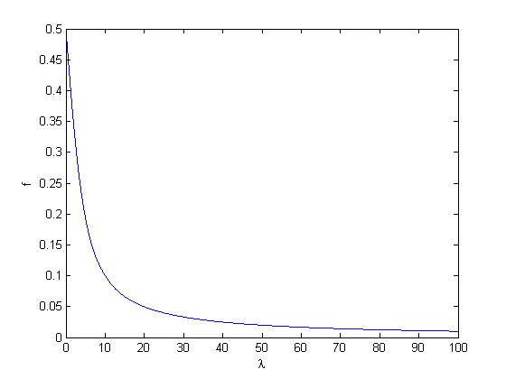
Suppose that a Laplacian p.d.f. has standard derivation λ, or P(w)= (λ/2)exp(-λ|w|), the optimal f which minimize the distortion can be determined analytically for Laplacian distribution, which decreases with increasing λ (i.e., decreasing standard derivation),
 (4)
(4)
Due to this distribution, the mean value of W inside a quantization interval is not located in the centre of corresponding interval. In order to reduce the quantization error, this effect is considered by using a rounding control parameter of f<∆/2. Such a rounding control parameter leads to smaller values of the quantized signal W', which are not located in the centre of a quantization interval.
Figure 5 shows the monotonic property between optimal f and Laplacian standard derivation λ.

Figure 5. The monotonic property between optimal f and Laplacian standard derivation λ
In the reference model of H.264/AVC, the probability distribution varies between Intra and Inter mode, thus different rounding control parameters are used. The rounding control parameter for Intra is f=∆/3 and for Inter it is f=∆/6. Therefore, the values of the quantized signal W' tend to be smaller than the value of the centre of the corresponding quantization interval. This behaviour is utilized to have a quantization that better fits to a non-uniform probability distribution of the input signal inside a quantization interval.
参考:http://www.h265.net/2009/06/quantization-techniques-in-jmkta-part-2.html


