Android 画笔Paint

转自 http://wuxiaolong.me/2016/08/20/Paint/

了解Android Paint,一篇就够。引用Aige《自定义控件其实很简单》系列博客的话“很多时候你压根不需要了解太多原理,只需站在巨人的丁丁上即可”,所谓前人种树后人好乘凉,这里记录下我的实践结果。

我们可以通过Paint中setter方法来为画笔设置属性:


浩浩荡荡来将这些方法一一过一遍:

set

1
void set(Paint src)

为当前画笔copy一个画笔

setARGB

1
void  setARGB(int a, int r, int g, int b)

设置Paint对象颜色,a代表透明度,r,g,b代表颜色值

插播:RGB与十六进制区别

一般在xml里定义颜色可以直接写:

1
android:textColor="#FF6281"


但是在code代码中就必须写成这样:

1
text.setTextColor(0xffff6281);


xml中透明度写不写无所谓,默认是ff不透明,但是代码中用十六进制0x来表示,就必须跟上ff透明度,不然会默认00全透明。

setAlpha

1
void  setAlpha(int a)

设置alpha透明度,范围为0~255

setAntiAlias

1
void  setAntiAlias(boolean aa)

是否抗锯齿

setColor

1
void  setColor(int color)

设置paint颜色

setColorFilter

1
ColorFilter setColorFilter (ColorFilter filter)

设置颜色过滤,ColorFilter有三个子类去实现ColorMatrixColorFilter、LightingColorFilter和PorterDuffColorFilter

ColorMatrixColorFilter

1
2
3
4
5
6
7
8
9
10
11
12
13
14
15
16
17
18
19
20
21
22
23
public class PaintCanvas extends View {
private Paint mPaint;
//省略构造方法
private void init() {
mPaint = new Paint();
mPaint.setAntiAlias(true);
// 生成色彩矩阵
ColorMatrix colorMatrix = new ColorMatrix(new float[]{
0.5F, 0, 0, 0, 0,
0, 0.5F, 0, 0, 0,
0, 0, 0.5F, 0, 0,
0, 0, 0, 1, 0,
});
mPaint.setColorFilter(new ColorMatrixColorFilter(colorMatrix));
}

@Override
protected void onDraw(Canvas canvas) {
Bitmap bitmap = BitmapFactory.decodeResource(getResources(), R.mipmap.logo);
canvas.drawBitmap(bitmap, 0, 0, mPaint);
}

}

第一行表示的R(红色)的向量,第二行表示的G(绿色)的向量,第三行表示的B(蓝色)的向量,最后一行表示A(透明度)的向量,这一顺序必须要正确不能混淆!这个矩阵不同的位置表示的RGBA值,其范围在0.0F至2.0F之间,1为保持原图的RGB值。每一行的第五列数字表示偏移值。


这是原图效果,增加ColorMatrix,效果如下:

LightingColorFilter

只有一个构造方法,LightingColorFilter (int mul, int add),参数1:mul全称是colorMultiply意为色彩倍增;参数2:add全称是colorAdd意为色彩添加,这两个值都是16进制的色彩值0xAARRGGBB。

1
2
// 设置颜色过滤,去掉绿色
mPaint.setColorFilter(new LightingColorFilter(0xFFFF00FF, 0x00000000));


效果如下:

PorterDuffColorFilter

也只有一个构造方法,PorterDuffColorFilter (int color, PorterDuff.Mode mode),参数1:16进制表示的颜色值;参数2:PorterDuff内部类Mode中的一个常量值,这个值表示混合模式。

1
2
// 设置颜色过滤,Color的值设为红色,模式PorterDuff.Mode.DARKEN变暗
mPaint.setColorFilter(new PorterDuffColorFilter(Color.RED, PorterDuff.Mode.DARKEN));


效果如下:

混合模式还有很多,不仅是应用于图像色彩混合,还应用于图形混合。

setDither

1
void setDither(boolean dither)

设定是否使用图像抖动处理,会使绘制出来的图片颜色更加平滑和饱满,图像更加清晰

setFakeBoldText

1
void setFakeBoldText(boolean fakeBoldText)

设置伪粗体文本

setFilterBitmap

1
void setFilterBitmap(boolean filter)

设置位图进行滤波处理

setHinting

1
void setHinting (int mode)

Added in API level 14,设置暗示模式,HINTING_OFF 或 HINTING_ON

setLetterSpacing

1
void setLetterSpacing (float letterSpacing)

Added in API level 21,设置文本字母间距,默认0,负值收紧文本

setLinearText

1
void setLinearText(boolean linearText)

设置线性文本

setMaskFilter

1
MaskFilter setMaskFilter (MaskFilter maskfilter)

设置滤镜的效果,MaskFilter有两个子类实现BlurMaskFilter, EmbossMaskFilter

BlurMaskFilter

设置画笔模糊阴影效果

1
mPaint.setMaskFilter(new BlurMaskFilter(20f, BlurMaskFilter.Blur.SOLID));


参数1:模糊延伸半径,必须>0;
参数2:有四种枚举
NORMAL,同时绘制图形本身内容+内阴影+外阴影,正常阴影效果
INNER,绘制图形内容本身+内阴影,不绘制外阴影
OUTER,不绘制图形内容以及内阴影,只绘制外阴影
SOLID,只绘制外阴影和图形内容本身,不绘制内阴影
BlurMaskFilter绘制的Bitmap基本完全不受影响

四种枚举效果如下:


EmbossMaskFilter

1
2
3
4
5
6
7
8
//Paint的setMaskFilter不被GPU支持,为了确保画笔的setMaskFilter能供起效,我们需要禁用掉GPU硬件加速或AndroidManifest.xml文件中设置android:hardwareAccelerated为false
if (Build.VERSION.SDK_INT >= Build.VERSION_CODES.HONEYCOMB) {
//View从API Level 11才加入setLayerType方法
//设置软件渲染模式绘图
this.setLayerType(View.LAYER_TYPE_SOFTWARE, null);
}
//设置浮雕滤镜效果,参数1:光源指定方向;参数2:环境光亮度,取值0-1,值越小越暗;参数3:镜面高光反射系数,值越小反射越强;参数4:模糊延伸半径
mPaint.setMaskFilter(new EmbossMaskFilter(new float[]{1, 1, 1}, 0.4f, 8f, 3f));

效果如下:

setPathEffect

1
PathEffect  setPathEffect(PathEffect effect)

设置路径效果,PathEffect有6个子类实现ComposePathEffect, CornerPathEffect, DashPathEffect, DiscretePathEffect, PathDashPathEffect, SumPathEffect
具体代码:

1
2
3
4
5
6
7
8
9
10
11
12
13
14
15
16
17
18
19
20
21
22
23
24
25
26
27
28
29
30
31
32
33
34
35
36
37
38
39
40
41
42
43
44
45
46
47
48
49
50
51
52
53
54
55
56
57
58
59
60
public class PaintCanvas extends View {
private Paint mPaint;
// 路径对象
private Path mPath;
private PathEffect[] pathEffects = new PathEffect[7];
private float mPhase=5;

//省略构造方法

private void init() {
mPaint = new Paint();
mPaint.setStyle(Paint.Style.STROKE);
mPaint.setStrokeWidth(5);
mPaint.setAntiAlias(true);
initPath();

}

private void initPath() {
// 实例化路径
mPath = new Path();
// 定义路径的起点
mPath.moveTo(10, 50);

// 定义路径的各个点
for (int i = 0; i <= 30; i++) {
mPath.lineTo(i * 35, (float) (Math.random() * 100));
}
//什么都不处理
pathEffects[0] = null;
//参数1:线段之间的圆滑程度
pathEffects[1] = new CornerPathEffect(10);
//参数1:间隔线条长度(length>=2),如float[] {20, 10}的偶数参数20定义了我们第一条实线的长度,
//而奇数参数10则表示第一条虚线的长度,后面不再有数据则重复第一个数以此往复循环;参数2:虚实线间距
pathEffects[2] = new DashPathEffect(new float[]{20, 10}, mPhase);
//参数1:值越小杂点越密集;参数2:杂点突出的大小,值越大突出的距离越大
pathEffects[3] = new DiscretePathEffect(5.0f, 10.0f);
Path path = new Path();
path.addRect(0, 0, 8, 8, Path.Direction.CCW);
//定义路径虚线的样式,参数1:path;参数2:实线的长度;参数3:虚实线间距
pathEffects[4] = new PathDashPathEffect(path, 20, mPhase, PathDashPathEffect.Style.ROTATE);
pathEffects[5] = new ComposePathEffect(pathEffects[2], pathEffects[4]);
//ComposePathEffect和SumPathEffect都可以用来组合两种路径效果,具体区别(不知道如何描述)小伙伴们自己试试
pathEffects[6] = new SumPathEffect(pathEffects[4], pathEffects[3]);
}

@Override
protected void onDraw(Canvas canvas) {
/*
* 绘制路径
*/
for (int i = 0; i < pathEffects.length; i++) {
mPaint.setPathEffect(pathEffects[i]);
canvas.drawPath(mPath, mPaint);
// 每绘制一条将画布向下平移250个像素
canvas.translate(0, 250);
}
}

}


效果如下:

setRasterizer

Rasterizer setRasterizer(Rasterizer rasterizer)
设置光栅化,API21已过时

setShader

1
Shader  setShader(Shader shader)

设置着色器,Shader 子类实现有BitmapShader, ComposeShader, LinearGradient, RadialGradient, SweepGradient

BitmapShader

对图形进行渲染,构造方法:

1
BitmapShader (Bitmap bitmap,Shader.TileMode tileX,Shader.TileMode tileY)


tileX、tileY参数Shader.TileMode有三个:
CLAMP 重复最后一个颜色至最后
MIRROR 重复着色的图像水平或垂直方向已镜像方式填充会有翻转效果
REPEAT 重复着色的图像水平或垂直方向

设置tileX、tileY为Shader.TileMode.CLAMP

1
2
3
4
5
6
7
8
9
10
11
12
13
14
15
16
17
18
19
20
21
22
public class PaintCanvas extends View {
private Paint mPaint;
private Context mContext;
private Bitmap mBitmap;
private BitmapShader mShader;

// 省略构造方法

private void init() {
mBitmap = BitmapFactory.decodeResource(mContext.getResources(), R.mipmap.logo);
mShader= new BitmapShader(mBitmap, Shader.TileMode.CLAMP, Shader.TileMode.CLAMP);
mPaint = new Paint();
mPaint.setAntiAlias(true);
}

@Override
protected void onDraw(Canvas canvas) {
mPaint.setShader(mBitmapShader);
canvas.drawCircle(500, 550, 500, mPaint);
}

}


效果如下:

设置tileX、tileY为Shader.TileMode.MIRROR
效果如下:

设置tileX、tileY为Shader.TileMode.REPEAT
效果如下:

LinearGradient

设置线性渐变效果,有两个构造函数

1
2
3
//坐标(x0,y0)渐变直线的起点,坐标(x1,y1)渐变直线的终点,color0和color1分别表示了渐变的起始颜色和终止颜色,TileMode也有CLAMP 、REPEAT 和 MIRROR三个取值
LinearGradient(float x0, float y0, float x1, float y1, int color0, int color1, Shader.TileMode tile)
LinearGradient(float x0, float y0, float x1, float y1, int[] colors, float[] positions,Shader.TileMode tile)


例子:

1
2
3
4
5
6
7
8
9
10
11
12
13
14
15
16
17
18
19
20
21
public class PaintCanvas extends View {
private Paint mPaint;
private Context mContext;
private Bitmap mBitmap;
private Shader mShader;

// 省略构造方法

private void init() {
mShader = new LinearGradient(0, 0, 500, 500, Color.BLUE, Color.GREEN,Shader.TileMode.CLAMP);
mPaint = new Paint();
mPaint.setAntiAlias(true);
}

@Override
protected void onDraw(Canvas canvas) {
mPaint.setShader(mBitmapShader);
canvas.drawCircle(500, 550, 400, mPaint);
}

}


效果如下:

设置REPEAT 和 MIRROR就不贴图片了,小伙伴们可以自己试试看看效果。

RadialGrdient

设置光束从中心向四周发散的辐射渐变效果,构造方法:

1
2
3
//坐标(centerX,centerY)中心点坐标,radius圆的半径,centerColor中心颜色,edgeColor圆的轮廓颜色,颜色逐渐从centerColor渐变到edgeColor,TileMode也有CLAMP 、REPEAT 和 MIRROR三个取值
RadialGradient(float centerX, float centerY, float radius, int centerColor, int edgeColor, Shader.TileMode tileMode)
RadialGradient(float centerX, float centerY, float radius, int[] colors, float[] stops, Shader.TileMode tileMode)


例子:

1
2
3
4
5
6
7
8
9
10
11
12
13
14
15
16
17
18
19
20
public class PaintCanvas extends View {
private Paint mPaint;
private Context mContext;
private Shader mShader;

// 省略构造方法

private void init() {
mShader = new RadialGradient(500, 500, 400, Color.BLUE, Color.GREEN, Shader.TileMode.CLAMP);
mPaint = new Paint();
mPaint.setAntiAlias(true);
}

@Override
protected void onDraw(Canvas canvas) {
mPaint.setShader(mBitmapShader);
canvas.drawCircle(500, 550, 400, mPaint);
}

}


效果如下:

设置REPEAT 和 MIRROR也不贴图片了。

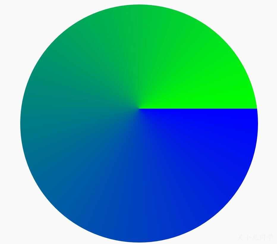
SweepGradient

设置绕着某中心点进行360度旋转渐变效果,构造方法:

1
2
3
4
//坐标(cx,cy)决定了中心点的位置,会绕着该中心点进行360度旋转。color0表示的是起点的颜色,color1表示的是终点的颜色
SweepGradient(float cx, float cy, int color0, int color1)
//坐标(cx,cy)决定了中心点的位置,colors颜色数组,position取值范围为[0,1],0和1都表示3点钟位置,0.25表示6点钟位置,0.5表示9点钟位置,0.75表示12点钟位置,诸如此类
SweepGradient(float cx, float cy, int[] colors, float[] positions)


例子:

1
2
3
4
5
6
7
8
9
10
11
12
13
14
15
16
17
18
19
20
public class PaintCanvas extends View {
private Paint mPaint;
private Context mContext;
private Shader mShader;

// 省略构造方法

private void init() {
mShader = new SweepGradient(500, 500, Color.BLUE, Color.GREEN);
mPaint = new Paint();
mPaint.setAntiAlias(true);
}

@Override
protected void onDraw(Canvas canvas) {
mPaint.setShader(mBitmapShader);
canvas.drawCircle(500, 550, 400, mPaint);
}

}


效果如下:

ComposeShader

混合,有两个构造函数

1
2
3
//shaderA对应下层图形,shaderB对应上层图形
ComposeShader(Shader shaderA, Shader shaderB, Xfermode mode)
ComposeShader(Shader shaderA, Shader shaderB, PorterDuff.Mode mode)


例子:

1
2
3
4
5
6
7
8
9
10
11
12
13
14
15
16
17
18
19
20
21
22
23
24
public class PaintCanvas extends View {
private Paint mPaint;
private Context mContext;
private Bitmap mBitmap;
private Shader bitmapShader, linearGradient, composeShader;

// 省略构造方法

private void init() {
mBitmap = BitmapFactory.decodeResource(mContext.getResources(), R.mipmap.logo);
bitmapShader = new BitmapShader(mBitmap, Shader.TileMode.MIRROR, Shader.TileMode.MIRROR);
linearGradient = new LinearGradient(0, 0, mBitmap.getWidth(), mBitmap.getHeight(), Color.BLUE, Color.GREEN, Shader.TileMode.CLAMP);
//bitmapShader对应下层图形,linearGradient对应上层图形,像素颜色混合采用MULTIPLY模式
composeShader = new ComposeShader(bitmapShader, linearGradient, PorterDuff.Mode.MULTIPLY);
mPaint = new Paint();
mPaint.setAntiAlias(true);
}

@Override
protected void onDraw(Canvas canvas) {
mPaint.setShader(mBitmapShader);
canvas.drawCircle(500, 550, 400, mPaint);
}
}


效果如下:

setShadowLayer

1
void setShadowLayer(float radius, float dx, float dy, int shadowColor)

图形添加一个阴影层效果

setStrikeThruText

1
void setStrikeThruText (boolean strikeThruText)

设置删除线

setStrokeCap

1
void setStrokeCap (Paint.Cap cap)

当设置setStyle是Stroke或StrokeAndFill,设置笔刷的图形样式,如圆形样式Cap.ROUND或方形样式Cap.SQUARE

setStrokeJoin

1
void setStrokeJoin (Paint.Join join)

当设置setStyle是Stroke或StrokeAndFill,设置绘制时各图形的结合方式,如影响矩形角的外轮廓

setStrokeMiter

1
void setStrokeMiter (float miter)

当设置setStyle是Stroke或StrokeAndFill,设置斜切

setStrokeWidth

1
void setStrokeWidth (float width)

当画笔样式为STROKE或FILL_OR_STROKE时,设置笔刷的粗细度

setStyle

1
void setStyle (Paint.Style style)

设置画笔样式,画笔样式分三种:
Paint.Style.STROKE:描边
Paint.Style.FILL_AND_STROKE:描边并填充
Paint.Style.FILL:填充

setSubpixelText

1
void setSubpixelText (boolean subpixelText)

有助于文本在LCD屏幕上的显示效果

setTextAlign

1
void setTextAlign(Paint.Align align)

设置文本对齐

setTextScaleX

1
void setTextScaleX(float scaleX)

设置文本缩放倍数,1.0f为原始

setTextSize

1
void setTextSize(float textSize)

设置字体大小

setTextSkewX

1
void setTextSkewX (float skewX)

设置斜体文字,skewX为倾斜弧度,默认值0,大于0,向左斜,小于0,向右斜

setTypeface

1
Typeface  setTypeface(Typeface typeface)

设置字体,Typeface包含了字体的类型,粗细,还有倾斜、颜色等。

1
mPaint.setTypeface(Typeface.SANS_SERIF);

setUnderlineText

1
void setUnderlineText(boolean underlineText)

设置下划线

setXfermode

1
Xfermode setXfermode (Xfermode xfermode)

设置图像混合模式,Xfermode 有个子类去实现PorterDuffXfermode

PorterDuffXfermode

构造方法PorterDuffXfermode(PorterDuff.Mode mode),参数就是上面的提到的,图形混合模式如图:

Dst:先画(下层)的图形;Src:后画(上层)的图形,然而被网上这张图片误导了,解释见孙群博客,他也给了最终运行效果:

我一一运行确实是如此,这里贴出Mode 为Screen代码:

1
2
3
4
5
6
7
8
9
10
11
12
13
14
15
16
17
18
19
20
21
22
23
24
25
26
27
28
29
30
31
32
33
34
35
public class PaintCanvas extends View {
private Paint mPaint;
private PorterDuffXfermode porterDuffXfermode;// 图形混合模式
private Context mContext;
private Bitmap mBitmap;
//省略构造方法

private void init() {
mBitmap = BitmapFactory.decodeResource(mContext.getResources(), R.mipmap.logo);
mPaint = new Paint();
mPaint.setAntiAlias(true);
// 实例化混合模式
porterDuffXfermode = new PorterDuffXfermode(PorterDuff.Mode.SCREEN);
}

@Override
protected void onDraw(Canvas canvas) {
int canvasWidth = canvas.getWidth();
int canvasHeight = canvas.getHeight();
//新建一个layer,放置在canvas默认layer的上部,产生的layer初始时是完全透明的
int layerId = canvas.saveLayer(0, 0, canvasWidth, canvasHeight, null, Canvas.ALL_SAVE_FLAG);
//dst是先画的图形
canvas.drawBitmap(mBitmap, 0, 0, mPaint);
//设置混合模式
mPaint.setXfermode(porterDuffXfermode);
//src是后画的图形
mPaint.setColor(0xFFFFCC44);
canvas.drawCircle(600, 600, 200, mPaint);
//还原混合模式
mPaint.setXfermode(null);
//或canvas.restore()把这个layer绘制到canvas默认的layer上去
canvas.restoreToCount(layerId);
}

}


例子源码

https://github.com/WuXiaolong/AndroidSamples/blob/master/app/src/main/java/com/wuxiaolong/androidsamples/paintcanvas/PaintCanvas.java


posted @ 2016-08-20 16:41  心夢無痕  阅读(861)  评论(0编辑  收藏  举报