linux设备驱动(24)dts补充
1 可以转换成设备的节点
首先,要说明的是设备树最初是为了解决大量重复的platform_device在mach-xx目录下,但在实现的过程重,设备树体现的是一个电路板的信息,添加了bootargs,memory,clock,interrupt等非platform_device的节点,这样就不能对所有的device_node转换成platform_device。memory,interrupt等虽然是硬件,但是不是platform_device。
内核的Documentation/devicetree/usage-model.txt目录中,有设备树使用的一个例子:
 1 /{
 2     compatible = "nvidia,harmony", "nvidia,tegra20";
 3     #address-cells = <1>;
 4     #size-cells = <1>;
 5     interrupt-parent = <&intc>;
 6
 7     chosen { };
 8     aliases { };
 9
10     memory {
11         device_type = "memory";
12         reg = <0x00000000 0x40000000>;
13     };
14
15     soc {
16         compatible = "nvidia,tegra20-soc", "simple-bus";
17         #address-cells = <1>;
18         #size-cells = <1>;
19         ranges;
20
21         intc: interrupt-controller@50041000 {
22             compatible = "nvidia,tegra20-gic";
23             interrupt-controller;
24             #interrupt-cells = <1>;
25             reg = <0x50041000 0x1000>, < 0x50040100 0x0100 >;
26         };
27
28         serial@70006300 {
29             compatible = "nvidia,tegra20-uart";
30             reg = <0x70006300 0x100>;
31             interrupts = <122>;
32         };
33
34         i2s1: i2s@70002800 {
35             compatible = "nvidia,tegra20-i2s";
36             reg = <0x70002800 0x100>;
37             interrupts = <77>;
38             codec = <&wm8903>;
39         };
40
41         i2c@7000c000 {
42             compatible = "nvidia,tegra20-i2c";
43             #address-cells = <1>;
44             #size-cells = <0>;
45             reg = <0x7000c000 0x100>;
46             interrupts = <70>;
47
48             wm8903: codec@1a {
49                 compatible = "wlf,wm8903";
50                 reg = <0x1a>;
51                 interrupts = <347>;
52             };
53         };
54     };
55
56     sound {
57         compatible = "nvidia,harmony-sound";
58         i2s-controller = <&i2s1>;
59         i2s-codec = <&wm8903>;
60     };
61 };
基本的我们看到,根节点肯定不是一个设备。aliases,aliases ,memory 也都不是一个platform_device。
以上面的i2c控制器的节点为例,一般来说i2c控制器下的子节点都是外设,但例子中的i2c节点不是根节点子节点。而是跟节点的子子节点。这样就不复合根节点下的有compatible 属性的节点,一般是子节点的特点了吗?
这里要说的是,对于这种情况,设备树做了特殊处理。即一般在一个节点的compatible 属性中函数一下的几个bus标识的话,它的子节点都会转换成平台设备platform_device。
1 const struct of_device_id of_default_bus_match_table[] = {
2     { .compatible = "simple-bus", },
3     { .compatible = "simple-mfd", },
4     { .compatible = "isa", },
5 #ifdef CONFIG_ARM_AMBA
6     { .compatible = "arm,amba-bus", },
7 #endif /* CONFIG_ARM_AMBA */
8     {} /* Empty terminated list */
9 };
既然i2c控制器被注册为了一个子节点,那么挂在i2c下面的设备呢?
通用行为是由父设备驱动程序在驱动程序.probe()时注册子设备。因此,i2c总线设备驱动程序将为每个子节点注册i2c_client,SPI总线驱动程序将注册其spi_device子节点,对于其他bus_types也是如此。
总结:
(1)除根节点以外,要能能被转换为platform_device,节点必须有compatible 属性。
(2)根节点下含有compatible 属性的子节点,一般被转换成platform_device?。
(3)函有compatible 属性的节点属性中函有基本的bus,其子节点中若也函有compatible 属性也会被转换成platform_device 。
2 device node到platform device的转换
在2.6的内核的时候,我们通常是在mach-xxx.c的一个文件中定义一个平台设备。
接下来说一下如何确定一个device_node是不是能被转换成一个platform_device。就是通过下面这个函数来分析的。
 1 static const struct of_device_id reserved_mem_matches[] = {
 2     { .compatible = "qcom,rmtfs-mem" },
 3     { .compatible = "qcom,cmd-db" },
 4     { .compatible = "ramoops" },
 5     {}
 6 };
 7
 8 static int __init of_platform_default_populate_init(void)
 9 {
10     struct device_node *node;
11
12     if (!of_have_populated_dt())
13         return -ENODEV;
14
15     /*
16      * Handle certain compatibles explicitly, since we don't want to create
17      * platform_devices for every node in /reserved-memory with a
18      * "compatible",
19      */
20     for_each_matching_node(node, reserved_mem_matches)
21         of_platform_device_create(node, NULL, NULL);
22
23     node = of_find_node_by_path("/firmware");
24     if (node) {
25         of_platform_populate(node, NULL, NULL, NULL);
26         of_node_put(node);
27     }
28
29     /* Populate everything else. */
30     of_platform_default_populate(NULL, NULL, NULL);
31
32     return 0;
33 }
34 arch_initcall_sync(of_platform_default_populate_init);
arch_initcall_sync函数是内核分阶段调用的一个例子。关于分阶段调用在内核中很常见,比如我们常用的module_init就是在某一阶段调用的。
看函数of_platform_default_populate_init
 1 static inline bool of_have_populated_dt(void)
 2 {
 3     return of_root != NULL;
 4 }
 5
 6 static int __init of_platform_default_populate_init(void)
 7 {
 8     struct device_node *node;
 9
10     if (!of_have_populated_dt())        //判断根节点是否存在,存在才有继续分析的意义
11         return -ENODEV;
12
13     /*
14      * Handle certain compatibles explicitly, since we don't want to create
15      * platform_devices for every node in /reserved-memory with a
16      * "compatible",   //处理高通对保留的内存节点的处理
17      */
18     for_each_matching_node(node, reserved_mem_matches)
19         of_platform_device_create(node, NULL, NULL);
20
21     node = of_find_node_by_path("/firmware");    //获取根节点下的firmware
22     if (node) {
23         of_platform_populate(node, NULL, NULL, NULL);    //处理这个节点下的节点
24         of_node_put(node);
25     }
26
27     /* Populate everything else.处理其他所有的节点*/
28     of_platform_default_populate(NULL, NULL, NULL);
29
30     return 0;
31 }
函数of_platform_default_populate
 1 const struct of_device_id of_default_bus_match_table[] = {
 2     { .compatible = "simple-bus", },
 3     { .compatible = "simple-mfd", },
 4     { .compatible = "isa", },
 5 #ifdef CONFIG_ARM_AMBA
 6     { .compatible = "arm,amba-bus", },
 7 #endif /* CONFIG_ARM_AMBA */
 8     {} /* Empty terminated list */
 9 };
10
11 //of_platform_default_populate函数的参数都是NULL
12 int of_platform_default_populate(struct device_node *root,
13                  const struct of_dev_auxdata *lookup,
14                  struct device *parent)
15 {
16     //这里是检测根节点下的所有节点,有of_default_bus_match_table表代表是cpu能访问的总线,即下面的子节点可以被转换成platform_device
17     return of_platform_populate(root, of_default_bus_match_table, lookup,
18                     parent);
19 }
函数of_platform_populate的详解见linux设备驱动(20)设备树详解4-kernel解析dts
3 设备树命名规则
DeviceTree发源于PowerPC架构,目的是为了为了消除代码中冗余的各种device注册代码而产生的,现在已经成为了linux的通用机制。设备树是一种用树状结构的方式来描述硬件信息,由Node(节点)、Property(属性)两种元素组成:
Node节点。在DTS中使用一对花括号”node-name{}”来定义;
Property属性。在Node中使用”property-name=value”字符串来定义;
3.1 设备树结构与规则
3.1.1 节点名(Node Names):node-name@unit-address
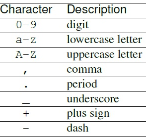
节点名称组件指定节点的名称。它的长度应为1到31个字符,且仅由下列总的字符集中的字符组成:
数字:0-9;大小写字母A(a)-Z(z);逗号 "," ;句号“.” ;下划线"_" ;加减号

3.1.2 路径名(Path Names)
通过指定从根节点到子节点再到所需节点的完整路径,可以唯一标识设备树中的一个节点。规则如下:
/node-name-1/node-name-2/node-name-N
其中,/是根节点路径。
3.1.3 属性(Properties)
设备树中的每个节点都有描述其节点特征的属性,属性由名称和值组成。
属性名:属性名称1到31个字符的字符串,字符规则如下表:

属性值:属性值是一个零个或多个字节的数组,其中包含与该属性关联的信息。
属性值详解:linux设备驱动(18)设备树详解2-基础知识
3.2 标准属性(Standard Properties)
3.2.1 compatible属性
Property name: compatible
Value type: <stringlist>
compatible属性值包含一个或多个字符串,这些字符串定义了设备的明确的编程模型。该字符串列表被用来匹配设备驱动程序。该属性的值由空终止字符串的串联列表组成,从最具体到最一般。它允许单个设备驱动程序与多个设备进行匹配。“compatible”属性通常用来device和driver的适配,推荐的格式为”manufacturer,model”。其中manufacturer是描述厂商名称的字符串,model值用于指定设备型号。
例如:
compatible = "fsl,mpc8641", "ns16550";
例中,操作系统将首先尝试找到支持fsl,mpc8641的设备驱动程序。如果找不到驱动程序,它将尝试找到支持更通用的ns16550设备类型的驱动程序。
3.2.2 phandle属性
Property name: phandle
Value type: <u32>
“phandle”属性通用一个唯一的id来标识一个Node,在property可以使用这个id来引用Node。
例如:
1 pic@10000000 {
2     phandle = <1>;
3     interrupt-controller;
4 };
5
6 another-device-node {
7     interrupt-parent = <1>;
8 };
定义phandle值为1另一个设备节点可以使用一个虚拟值1引用pic节点。
3.2.3 status属性
Property name: status
Value type: <string>
status属性指示设备的运行状态,下面列出了各状态值的定义。
"okay":指示设备正在运行
"disabled":表示该设备当前无法运行,但是将来可能会运行(比如未插入或关闭的某些设备)。
"reserved":表示设备可运行,但不应使用。通常,它用于由另一个软件组件(例如平台固件)控制的设备。
"fail":表示设备无法运行。在设备中检测到严重错误,且不进行修复就无法运行。
"fail-sss":表示设备无法运行。在设备中检测到严重错误,且如果不进行修复就无法开始运行。sss的部分指定设备,并指示侦测到的错误情况。
3.2.4 #address-cells, #size-cells
Property name: #address-cells, #size-cells
Value type: <u32>
#address-cells和 #size-cells属性可作用于设备树结构中具有子节点的任何设备节点,并定义子节点设备的该属性规则。#address-cells属性定义<u32>用于在子节点的 reg 属性中对地址字段进行编码的单元格数。 #size-cells属性定义<u32>用于在子节点的 reg 属性中对大小字段进行编码的单元数。#address-cells和#size-cells属性不会从设备树中的父节点继承。
例如:
 1 soc {
 2     #address-cells = <1>;
 3     #size-cells = <1>;
 4     serial@4600 {
 5         compatible = "ns16550";
 6         reg = <0x4600 0x100>;
 7         clock-frequency = <0>;
 8         interrupts = <0xA 0x8>;
 9         interrupt-parent = <&ipic>;
10     };
11 };
例中,soc 节点的#address-cells数和#size-cells属性都设置为 1。此设置指定需要一个单元来表示地址,并且需要一个单元来表示此节点的子节点大小。串行设备 reg 属性必须遵循父 (soc) 节点中的此规范,地址由1个单元格 (0x4600) 表示,大小由1个单元格 (0x100) 表示。
3.2.5 reg 属性
Property name: reg
Property value: <prop-encoded-array>
reg 属性描述设备资源在其父总线定义的地址空间内的地址。最常见的情况是,表示内存映射 IO 寄存器块的偏移量和长度,但在某些总线类型上可能具有不同的含义。根节点定义的地址空间中的地址是 CPU 的真实地址。它的<prop-encoded-array>值,由任意数目的地址和长度对组成[地址长度]。<u32>指定特定于总线上的地址和长度所需的单元数,由设备节点的父节点中#address-cells和#size-cells属性指定。如果父节点#size-cells值 为0,则应省略 reg 值中的长度字段。
例如:
假设片上系统内的设备有两个寄存器块,SOC 中的偏移 0x3000 的 32 字节块和偏移 0xFE00 的 256 字节块。reg 属性的编码方式如下(假设#address-cells和#size-cells值为 1)
reg = <0x3000 0x20 0xFE00 0x100>;
3.2.6 ranges属性
Property name: ranges
Value type: <empty> or <prop-encoded-array>(编码为任意数量的(子总线地址、父总线地址、长度)三阵列)
ranges提供了一种在总线的地址空间(子地址空间)和总线节点的父节点(父地址空间)的地址空间之间定义映射或转换的方法。
child-bus-address是子总线地址空间内的物理地址。表示地址的单元数与总线相关,可以从该节点的#address-cells(显示范围属性的节点)确定。
parent-bus-address是父总线地址空间中的物理地址。表示父地址的单元数与总线相关,可以从定义父地址空间的节点的#address-cells属性确定。
length指定子地址空间中范围的大小。表示大小的单元数可以从该节点的#size-cells(显示范围属性的节点)确定。
如果属性使用<empty>值定义,则指定父地址空间和子地址空间相同,并且不需要地址转换。如果该属性不存在于总线节点中,则假定节点的子节点和父地址空间之间不存在映射。
例如:
 1 soc {
 2     compatible = "simple-bus";
 3     #address-cells = <1>;
 4     #size-cells = <1>;
 5     ranges = <0x0 0xe0000000 0x00100000>;
 6     serial@4600 {
 7         device_type = "serial";
 8         compatible = "ns16550";
 9         reg = <0x4600 0x100>;
10         clock-frequency = <0>;
11         interrupts = <0xA 0x8>;
12         interrupt-parent = <&ipic>;
13     };
14 };
ranges = <0x0 0xe0000000 0x00100000>;
此属性值指定在1024 KB 地址空间范围,以物理 0x0 地址寻址的子节点映射到物理父地址 0xe000000 ,可以映射到父地址的长度为0x00100000。通过此映射,串行设备节点在父地址 的位置0xe0004600,长度0x100范围内。
为了对ranges属性更深入的理解,后面有详细实例详解。
3.3 中断属性
在设备树中,存在逻辑中断树,该逻辑中断树表示平台硬件中中断的层次结构和路由。在设备树中,使用interruptparent属性表示中断源与中断控制器的物理连线。产生中断的设备节点包含一个中断父级属性,该属性具有一个虚拟值,该值指向该设备的中断所路由到的设备(通常是中断控制器)。每个中断产生设备都包含一个中断属性,该属性的值描述该设备的一个或多个中断源。每个源都在中断说明符填充相关信息。中断说明符的格式和含义是由中断域所确定的,即它取决于中断域根节点上节点的属性。中断域的根使用#interrupt-cells属性定义中断说明符进行编码所需值的数量。如果产生中断的设备不具有父中断属性,则假定其父中断为其设备树父节点。
和中断相关的node可以分成3种:
1 “Interrupt Generating Devices”,中断发生设备,这种设备可以发生中断。
2 “Interrupt Controllers”,中断控制器,处理中断。
3 “Interrupt Nexus”,中断联结,路由中断给中断控制器。
3.3.1 中断产生设备属性(Properties for Interrupt Generating Devices)
Property:interrupts
Value type: <prop-encoded-array>(编码为任意数量的中断说明符)
interrupts属性的值由任意数量的中断说明符组成。中断说明符的格式由绑定的中断域根定义。“interrupts”属性定义了设备的中断解析,定义设备生成的一个或多个中断。根据其”interrupt-parent”node中定义的“#interrupt-cells”来解析。比如#interrupt-cells=2,表示用2个单元解析“interrupts”属性。
例如:
interrupts = <0xA 8>;
在open PIC–compatible中断域中,中断说明符的通用定义由两个单元组成;第二个单元由两个单元组成。中断号和级别/检测信息。例子中定义了一个中断说明符,中断号为0xA,级别/检测编码为8。
Property: interrupt-parent
Value type: <phandle>
“interrupt-parent”属性用来制定当前设备的Interrupt Controllers/Interrupt Nexus,phandle指向对应的node。
3.3.2 中断控制器属性(Properties for Interrupt Controllers)
Property: #interrupt-cells
Value type: <u32>
“#interrupt-cells”属性用来规定连接到该中断控制器上的设备节点里"interrupts"属性的解析长度(所需单元数)。
Property: interrupt-controller
Value type: <empty>
“interrupt-controller”属性用来声明当前node为中断控制器。
3.3.3 中断联结属性(Interrupt Nexus Properties)
Property: #interrupt-cells
Value type: <u32>
“#interrupt-cells”属性用来规定连接到该中断控制器上的设备的”interrupts”属性的解析长度。
Property: interrupt-map
Value type: <prop-encoded-array>(编码为任意数量的中断映射项)
“interrupt-map”属性用来描述interrupt nexus设备对中断的路由。解析格式为5个元素序列:
child unit address:被映射的子节点的单元地址。该属性的cells长度由其所在的总线节点的#address-cells属性描述。
child interrupt specifier:被映射的子节点的中断说明符。该节点所需的单元数由#interrupt-cells属性(包含中断映射属性的关系节点)指定。
interrupt-parent:单个值指向子域要映射到的父中断。
parent unit address:父中断域中的单元地址。指定此地址所需的单元数由父中断域指向节点的#address-cells属性描述。
parent interrupt specifier:父域中的中断说明符。所需的单元数由父中断域指向节点的#interrupt-cells属性描述。
例如:
 1 soc {
 2     compatible = "simple-bus";
 3     #address-cells = <1>;
 4     #size-cells = <1>;
 5     open-pic {
 6         clock-frequency = <0>;
 7         interrupt-controller;
 8         #address-cells = <0>;
 9         #interrupt-cells = <2>;
10     };
11     pci {
12         #interrupt-cells = <1>;
13         #size-cells = <2>;
14         #address-cells = <3>;
15         interrupt-map-mask = <0xf800 0 0 7>;
16         interrupt-map = <
17         /* IDSEL 0x11 - PCI slot 1 */
18         0x8800 0 0 1 &open-pic 2 1 /* INTA */
19         0x8800 0 0 2 &open-pic 3 1 /* INTB */
20         0x8800 0 0 3 &open-pic 4 1 /* INTC */
21         0x8800 0 0 4 &open-pic 1 1 /* INTD */
22         /* IDSEL 0x12 - PCI slot 2 */
23         0x9000 0 0 1 &open-pic 3 1 /* INTA */
24         0x9000 0 0 2 &open-pic 4 1 /* INTB */
25         0x9000 0 0 3 &open-pic 1 1 /* INTC */
26         0x9000 0 0 4 &open-pic 2 1 /* INTD */
27         >;
28     };
29 };
中断映射表的第一行指定插槽1的INTA的映射:
1 child unit address: 0x8800 0 0
2 child interrupt specifier: 1
3 interrupt parent: &open-pic
4 parent unit address: (empty because #address-cells = <0> in the open-pic node)
5 parent interrupt specifier: 2 1
4 ranges的实例详解
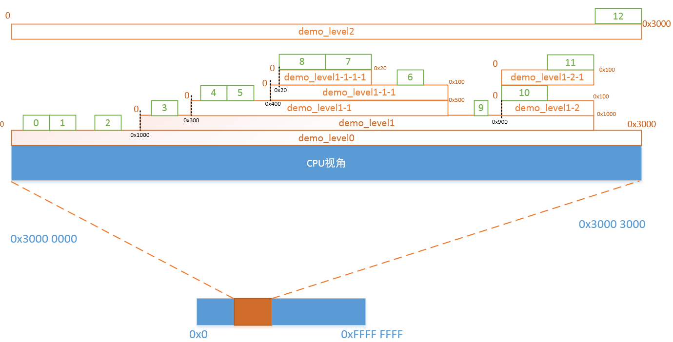
在设备树中有时会看到ranges属性,这个ranges属性可以达到什么效果?下面结合一个实际的例子来看看。
4.1 设备树
下面是我们将要实验的设备树的例子:
  1 / {
  2     #address-cells = <1>;
  3     #size-cells = <1>;
  4
  5     demo_level0 {
  6         compatible = "simple-bus";
  7         ranges = <0x0 0x3000000 0x3000>;
  8         #address-cells = <1>;
  9         #size-cells = <1>;
 10
 11         range@0 {
 12             compatible = "range";
 13             reg = <0x100 0x200>;
 14             reg-names = "range0";
 15         };
 16
 17         range@1 {
 18             compatible = "range";
 19             reg = <0x300 0x200>;
 20             reg-names = "range1";
 21         };
 22
 23         range@2 {
 24             compatible = "range";
 25             reg = <0x600 0x200>;
 26             reg-names = "range2";
 27         };
 28
 29         demo_level1 {
 30             compatible = "simple-bus";
 31             ranges = <0x0 0x1000 0x1000>;
 32             #address-cells = <1>;
 33             #size-cells = <1>;
 34
 35             range@3 {
 36                 compatible = "range";
 37                 reg = <0x100 0x200>;
 38                 reg-names = "range3";
 39             };
 40
 41             demo_level1-1 {
 42                 compatible = "simple-bus";
 43                 ranges = <0x0 0x300 0x500>;
 44                 #address-cells = <1>;
 45                 #size-cells = <1>;
 46
 47                 range@4 {
 48                     compatible = "range";
 49                     reg = <0x100 0x200>;
 50                     reg-names = "range4";
 51                 };
 52
 53                 range@5 {
 54                     compatible = "range";
 55                     reg = <0x300 0x100>;
 56                     reg-names = "range5";
 57                 };
 58
 59                 demo_level1-1-1 {
 60                     compatible = "simple-bus";
 61                     ranges = <0x0 0x400 0x100>;
 62                     #address-cells = <1>;
 63                     #size-cells = <1>;
 64
 65                     range@6 {
 66                         compatible = "range";
 67                         reg = <0x50 0x30>;
 68                         reg-names = "range6";
 69                     };
 70
 71                     demo_level1-1-1-1 {
 72                         compatible = "simple-bus";
 73                         ranges = <0x0 0x20 0x20>;
 74                         #address-cells = <1>;
 75                         #size-cells = <1>;
 76
 77                         range@7 {
 78                             compatible = "range";
 79                             reg = <0x10 0x10>;
 80                             reg-names = "range7";
 81                         };
 82
 83                         range@8 {
 84                             compatible = "range";
 85                             reg = <0x0 0x10>;
 86                             reg-names = "range8";
 87                         };
 88                     };
 89                 };
 90             };
 91
 92             range@9 {
 93                 compatible = "range";
 94                 reg = <0x800 0x50>;
 95                 reg-names = "range9";
 96             };
 97
 98             demo_level1-2 {
 99                 compatible = "simple-bus";
100                 ranges = <0x0 0x900 0x100>;
101                 #address-cells = <1>;
102                 #size-cells = <1>;
103
104                 range@10 {
105                     compatible = "range";
106                     reg = <0x0 0x50>;
107                     reg-names = "range10";
108                 };
109
110                 demo_level1-2-1 {
111                     compatible = "simple-bus";
112                     ranges;
113                     #address-cells = <1>;
114                     #size-cells = <1>;
115
116                     range@11 {
117                         compatible = "range";
118                         reg = <0x50 0x30>;
119                         reg-names = "range11";
120                     };
121                 };
122             };
123         };
124
125         demo_level2 {
126             compatible = "simple-bus";
127             ranges;
128             #address-cells = <1>;
129             #size-cells = <1>;
130
131             range@12 {
132                 compatible = "range";
133                 reg = <0x2000 0x1000>;
134                 reg-names = "range12";
135             };
136         };
137     }
138 };
4.2 驱动
 1 #include <linux/init.h>
 2 #include <linux/module.h>
 3 #include <linux/platform_device.h>
 4 #include <linux/of.h>
 5
 6 static int demo_range_probe(struct platform_device *pdev)
 7 {
 8     struct resource *res = platform_get_resource(pdev, IORESOURCE_MEM, 0);
 9
10     printk(KERN_INFO "%s start: 0x%x, end: 0x%x\n",
11         res->name, res->start, res->end + 1);
12
13     return 0;
14 }
15
16 static int demo_range_remove(struct platform_device *pdev)
17 {
18     return 0;
19 }
20
21 static const struct of_device_id demo_range_of_match[]  = {
22     { .compatible = "range"},
23     {},
24 };
25
26 static struct platform_driver demo_range_driver = {
27     .driver = {
28         .name = "demo_range",
29         .owner = THIS_MODULE,
30         .of_match_table = demo_range_of_match,
31     },
32     .probe = demo_range_probe,
33     .remove = demo_range_remove,
34 };
35 module_platform_driver(demo_range_driver);
36
37 MODULE_LICENSE("GPL v2");
在驱动中会获得memory资源,然后将start和(end+1)打印出来,之所以这里用(end+1),仅仅是为了便于理解下面的kernel log。
4.3 验证
编译驱动,然后加载,可以看到下面的打印信息:
[root@vexpress mnt]# insmod demo_range.ko
[  382.940402] range0 start: 0x3000100, end: 0x3000300
[  382.940697] range1 start: 0x3000300, end: 0x3000500
[  382.941448] range2 start: 0x3000600, end: 0x3000800
[  382.941657] range3 start: 0x3001100, end: 0x3001300
[  382.941855] range4 start: 0x3001400, end: 0x3001600
[  382.942057] range5 start: 0x3001600, end: 0x3001700
[  382.942262] range6 start: 0x3001750, end: 0x3001780
[  382.942470] range7 start: 0x3001730, end: 0x3001740
[  382.942684] range8 start: 0x3001720, end: 0x3001730
[  382.949796] range9 start: 0x3001800, end: 0x3001850
[  382.950023] range10 start: 0x3001900, end: 0x3001950
[  382.950603] range11 start: 0x3001950, end: 0x3001980
[  382.950805] range12 start: 0x3002000, end: 0x3003000
总结:
(1)ranges属性值的格式 <local地址, parent地址, size>, 表示将local地址向parent地址的转换。
比如对于#address-cells和#size-cells都为1的话,以<0x0 0x10 0x20>为例,表示将local的从0x0~(0x0 + 0x20)的地址空间映射到parent的0x10~(0x10 + 0x20)
其中,local地址的个数取决于当前含有ranges属性的节点的#address-cells属性的值,size取决于当前含有ranges属性的节点的#size-cells属性的值。
而parent地址的个数取决于当前含有ranges属性的节点的parent节点的#address-cells的值。
(2)对于含有ranges属性的节点的子节点来说,其reg都是基于local地址的。
(3)ranges属性值为空的话,表示1:1映射。
(4)对于没有ranges属性的节点,代表不是memory map区域。
对照上面的log理解下面的框图:

参考博文:https://blog.csdn.net/qq_16777851/java/article/details/87870567


