TMC2300防丢步步进电机驱动芯片使用小结
概述
TMC2300驱动电压2-11V,QFN3*3 20PIN。具有两种驱动方式(1.脉冲+方向引脚 2.单线串口),可实现无感负载测量,通过负载测量可实现电机的防丢步设计。
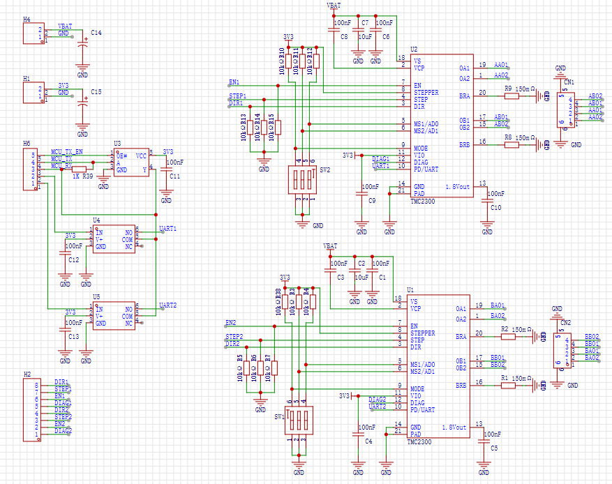
典型应用框图及引脚说明
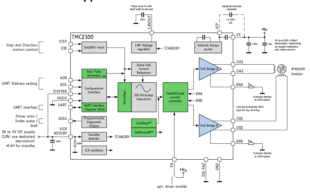
STEP: 脉冲输入引脚 DIR :方向控制引脚 MODE:0:单线串口控制模式 1:脉冲+方向控制模式
AD0、AD1:在脉冲+方向模式下配置驱动细分,在单线串口模式下是硬件通讯地址。
DIAG:在单线串口模式下,可配置为脉冲输出,电机每步进一步输出一个脉冲。也可配置为丢步输出,当检测即将丢步时输出一个脉冲。
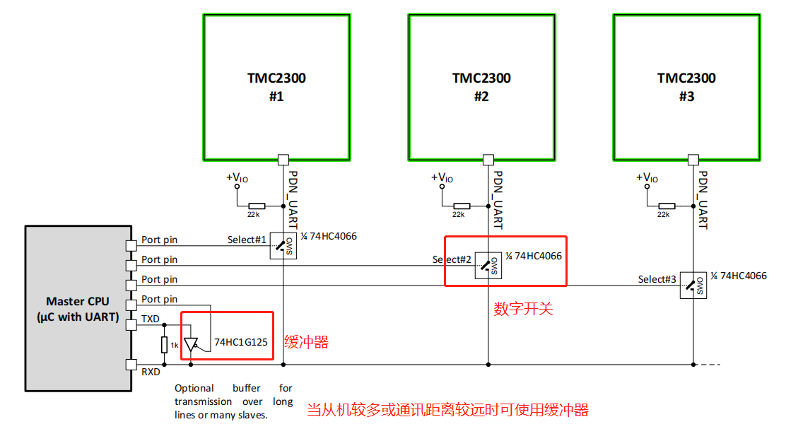
典型拓扑结构
通过配合TMC2300的AD0与AD1引脚,每个模拟开关后可以挂在4个驱动芯片。
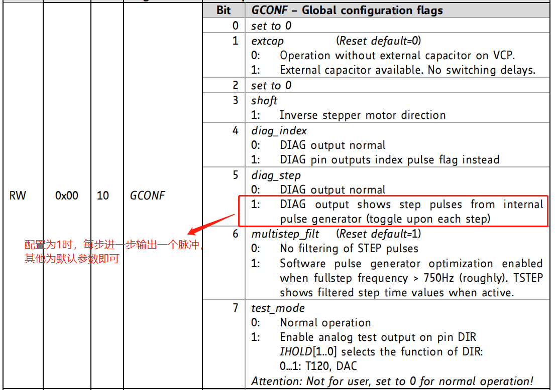
重点寄存器说明
1.全局配置寄存器
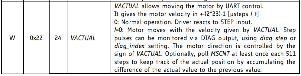
2.速度设置寄存器(写入一个int型数据,int型数据的符号控制旋转方向)
当速度写入0时,芯片可通过外部脉冲实现速度控制。即使在串口模式下,DIR方向控制引脚依然起作用。
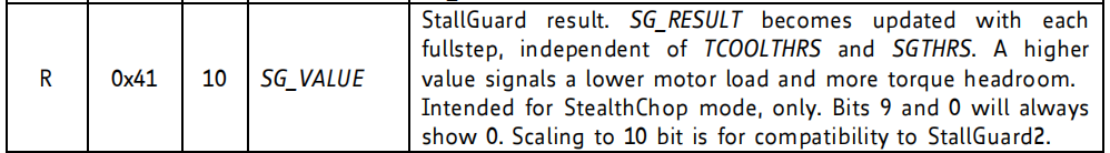
3.负载寄存器,共10位有效位,但第0、第9位始终为0。当负载越大时该寄存器里的值越小。
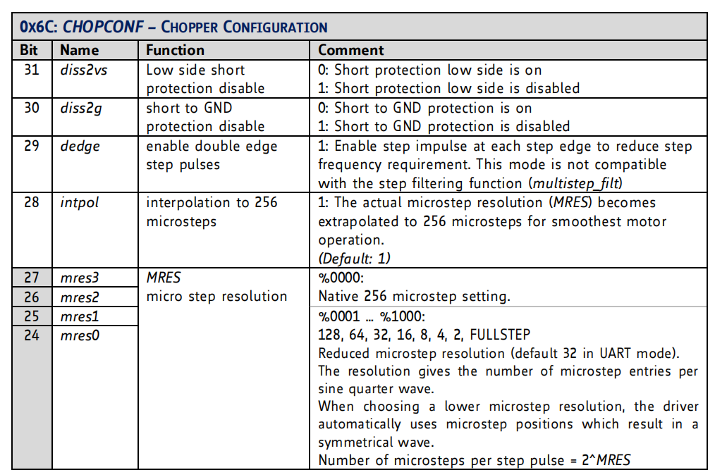
4.恒流斩波配置寄存器
mres0-3共4位用于步进电机的驱动细分配置,0-9分别对应256/128/64/32/16/8/4/2细分、整步
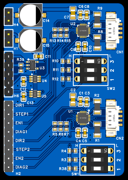
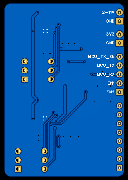
自己做的评估板
部分代码
uint8_t TMC2300_ReadWrite_buf[8] = { 0 };

void tmc2300_writeInt(uint8_t chip_address,uint8_t reg_address, int32_t value)
{
		TMC2300_ReadWrite_buf[0] = 0x05;
		TMC2300_ReadWrite_buf[1] = chip_address;
		TMC2300_ReadWrite_buf[2] = reg_address | 0x80;
		TMC2300_ReadWrite_buf[3] = (value >> 24) & 0xFF;
		TMC2300_ReadWrite_buf[4] = (value >> 16) & 0xFF;
		TMC2300_ReadWrite_buf[5] = (value >> 8 ) & 0xFF;
		TMC2300_ReadWrite_buf[6] = (value      ) & 0xFF;
		swuart_calcCRC(TMC2300_ReadWrite_buf, 8);

		HAL_UART_Transmit_DMA(&huart2, TMC2300_ReadWrite_buf, 8);
}

void tmc2300_readInt(uint8_t chip_address,uint8_t reg_address)
{

	TMC2300_ReadWrite_buf[0] = 0x05;
	TMC2300_ReadWrite_buf[1] = chip_address;
	TMC2300_ReadWrite_buf[2] = reg_address;

	swuart_calcCRC(TMC2300_ReadWrite_buf, 4);

	HAL_UART_Transmit_DMA(&huart2, TMC2300_ReadWrite_buf, 4);

}

void swuart_calcCRC(uint8_t* datagram, uint8_t datagramLength)
{
    int i,j;
    uint8_t* crc = datagram + (datagramLength-1); // CRC located in last byte of message
    uint8_t currentByte;
    *crc = 0;
    for (i=0; i<(datagramLength-1); i++)
    { // Execute for all bytes of a message
        currentByte = datagram[i]; // Retrieve a byte to be sent from Array
        for (j=0; j<8; j++)
        {
            if ((*crc >> 7) ^ (currentByte&0x01)) // update CRC based result of XOR operation
            {
                *crc = (*crc << 1) ^ 0x07;
            }
            else
            {
                *crc = (*crc << 1);
            }
            currentByte = currentByte >> 1;
        } // for CRC bit
    } // for message byte
}

 浙公网安备 33010602011771号