Raspberry Pi & GPIO All In One
Raspberry Pi & GPIO All In One
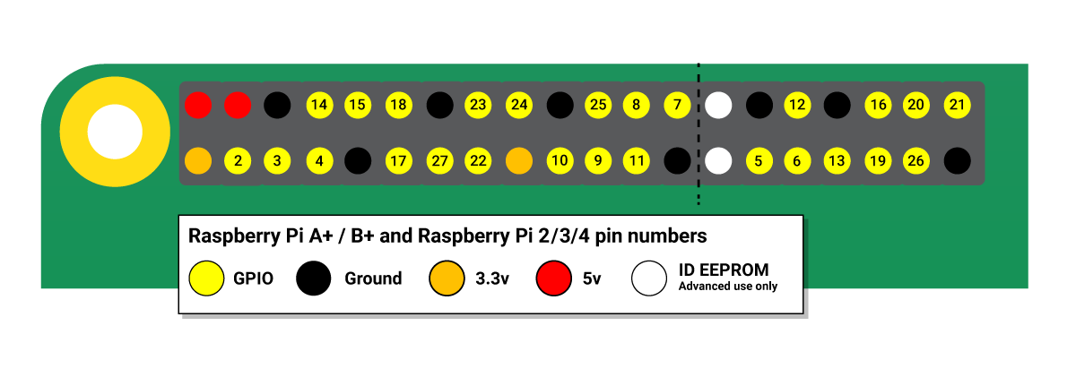
GPIO

https://www.raspberrypi.com/documentation/computers/os.html#gpio-and-the-40-pin-header
pinout ===
pin out/ p in out
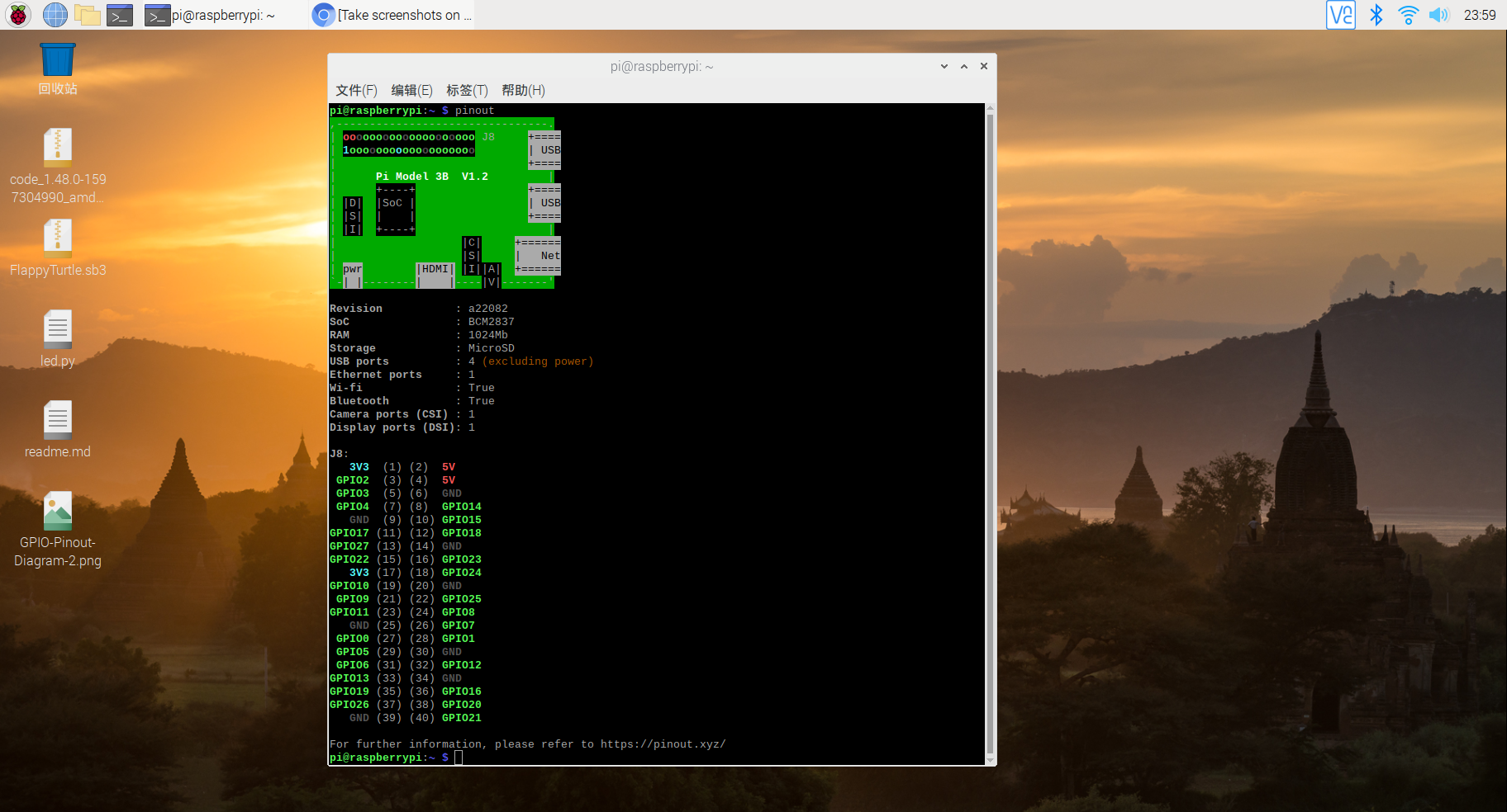
pi@raspberrypi:~ $ pinout
,--------------------------------.
| oooooooooooooooooooo J8     +====
| 1ooooooooooooooooooo        | USB
|                             +====
|      Pi Model 3B  V1.2         |
|      +----+                 +====
| |D|  |SoC |                 | USB
| |S|  |    |                 +====
| |I|  +----+                    |
|                   |C|     +======
|                   |S|     |   Net
| pwr        |HDMI| |I||A|  +======
`-| |--------|    |----|V|-------'

Revision           : a22082
SoC                : BCM2837
RAM                : 1024Mb
Storage            : MicroSD
USB ports          : 4 (excluding power)
Ethernet ports     : 1
Wi-fi              : True
Bluetooth          : True
Camera ports (CSI) : 1
Display ports (DSI): 1

J8:
   3V3  (1) (2)  5V
 GPIO2  (3) (4)  5V
 GPIO3  (5) (6)  GND
 GPIO4  (7) (8)  GPIO14
   GND  (9) (10) GPIO15
GPIO17 (11) (12) GPIO18
GPIO27 (13) (14) GND
GPIO22 (15) (16) GPIO23
   3V3 (17) (18) GPIO24
GPIO10 (19) (20) GND
 GPIO9 (21) (22) GPIO25
GPIO11 (23) (24) GPIO8
   GND (25) (26) GPIO7
 GPIO0 (27) (28) GPIO1
 GPIO5 (29) (30) GND
 GPIO6 (31) (32) GPIO12
GPIO13 (33) (34) GND
GPIO19 (35) (36) GPIO16
GPIO26 (37) (38) GPIO20
   GND (39) (40) GPIO21

For further information, please refer to https://pinout.xyz/
pi@raspberrypi:~ $
Pinout
引脚排列
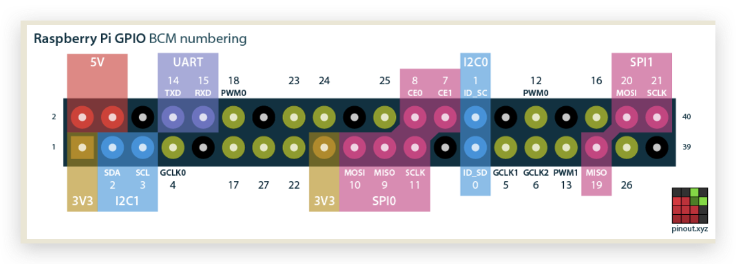
GPCLK0
https://pinout.xyz/pinout/pin7_gpio4
BCM 17
https://pinout.xyz/pinout/pin11_gpio17
GPIO 12 / BCM 12
Physical/Board pin 32
GPIO/BCM pin 12
Wiring Pi pin 26
物理/电路板引脚 32 ✅
GPIO/BCM 引脚 12 ✅
接线 Pi 引脚 26

https://pinout.xyz/pinout/pin32_gpio12
$ pinout

3V3
3.3V正极 +,高电平
5V
5V正极 +,高电平
GND
Ground负极 - ,接地,低电平
GPIO
general purpose input/output
-
普通 GPIO,如
GPIO 17,可以控制电平的高低状态,改变 LED 的显示状态 -
特殊 GPIO, 如 ?,一般
高级功能才用的到,暂不讲解
LED 点亮
电路图
电源正极(3v3 pin) => 电阻 => LED 正极(长脚) => 电源负极(GND pin)

面包板
电阻 200Ω (大于 50Ω? 200KΩ 不好使?)
LED 长正短负
杜邦线,红正黑负
面包板,正负极是如何划分的? https://www.cnblogs.com/xgqfrms/p/17266194.html
红线接正极,黑线接负极
220 欧姆电阻器, 200k is not ok
触觉 按钮 开关
LED 长针是正极,短针是负极
https://youtu.be/XrlR7cHSltw?t=370
You can test whether your GPIO pins and LEDs are working by building the circuit below. You can use any resistor over about 50Ω.
The LED is connected directly to the GND pin and the 3V3 pin via the 330 Ohm resistor, and should light up.
Be sure to connect your LED the correct way round; the longer leg should be connected to the 3V3 pin:
GPIO with Scratch 2
GPIO with Python
refs
面包板使用教程 All In One
https://www.cnblogs.com/xgqfrms/p/17266194.html
https://www.raspberrypi.org/documentation/usage/gpio/
https://www.cnblogs.com/xgqfrms/p/13474349.html
https://www.cnblogs.com/xgqfrms/p/16478328.html
©xgqfrms 2012-2020
www.cnblogs.com/xgqfrms 发布文章使用:只允许注册用户才可以访问!
原创文章,版权所有©️xgqfrms, 禁止转载 🈲️,侵权必究⚠️!
本文首发于博客园,作者:xgqfrms,原文链接:https://www.cnblogs.com/xgqfrms/p/13511057.html
未经授权禁止转载,违者必究!