
GD32F30x_AD5693R驱动程序
一、工具
1、硬件:GD32F30x系列单片机
2、编译环境:KEIL
3、AD5693R芯片:AD5693RxRM
二、芯片简介
AD5693R是一款16位单通道缓冲电压输出DAC,内部集成默认2.5 V基准电压源,内部基准电压源默认使能 ,提供2ppm/℃漂移。输出范围可编程设置为0 V至 Vref或者0V至2xVref。数据通过I2C串行接口以24位字格式写入,支持标准(100kHz)和快速(400kHz)数据传输模式,不支持10位寻址和广播寻址。
输出电压计算公式:
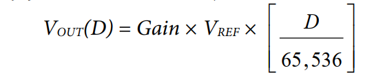
D是载入DAC寄存器的二进制编码的十进制等效值。
Gain是输出放大器的增益,默认设置为1。 也可以将该增益设置为2。
Vref是参比电压,默认使用内部2.5V电压。
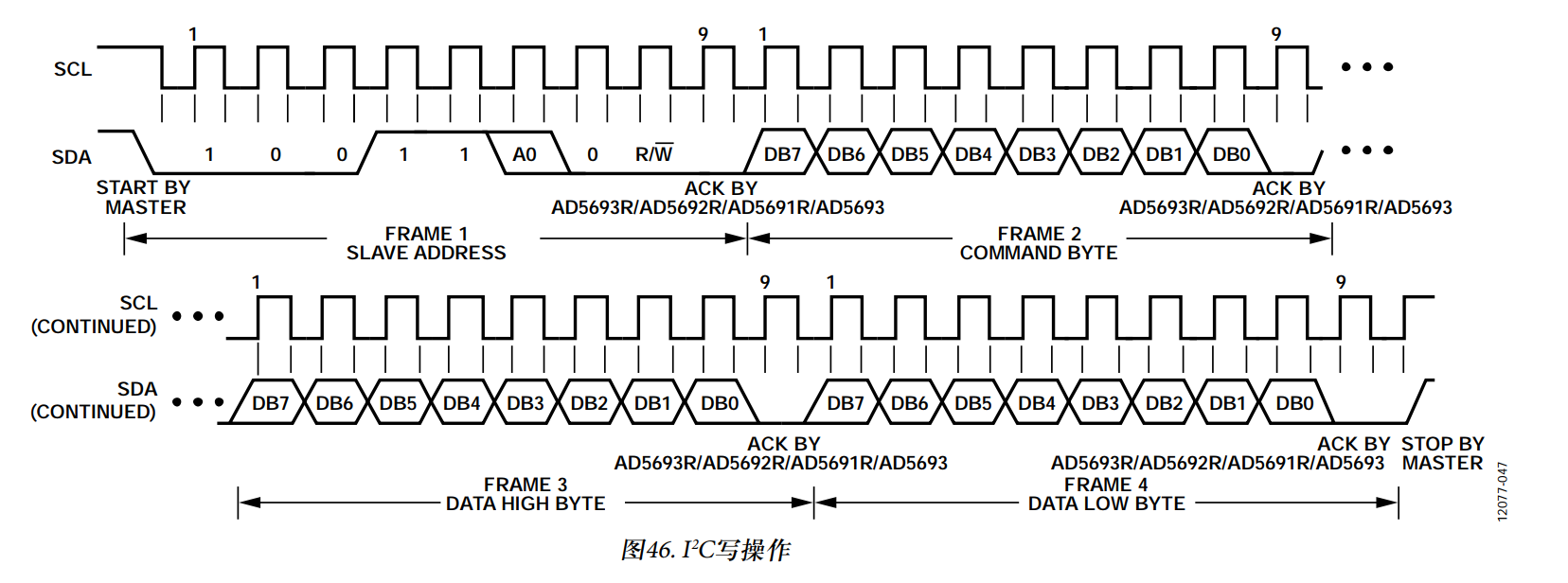
三、芯片I2C协议
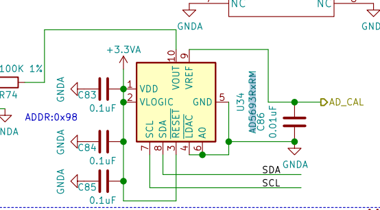
四、硬件电路
五、程序编写
I2C配置
- I2C引脚初始化
/**
  *****************************************************************************
  * @Name   : I2C1_GPIO_Configuration
  * @Brief  : I2C1引脚初始化
  *****************************************************************************
**/
void I2C1_GPIO_Configuration(void)
{
    rcu_periph_clock_enable(RCU_GPIOB);
    rcu_periph_clock_enable(RCU_AF);

    gpio_init(GPIOB, GPIO_MODE_AF_OD, GPIO_OSPEED_50MHZ, GPIO_PIN_10 | GPIO_PIN_11);
}
2. I2C外设配置
/**
  *****************************************************************************
  * @Name   : I2C1_Configuration
  * @Brief  : I2C1配置
  * @Input  :
  * @Output :
  * @Return :
  *****************************************************************************
**/
void I2C1_Configuration(void)
{
    I2C1_GPIO_Configuration();
    rcu_periph_clock_enable(RCU_I2C1);

    i2c_clock_config(I2C1, 250000, I2C_DTCY_2);/*设置I2C频率*/
    i2c_mode_addr_config(I2C1, I2C_I2CMODE_ENABLE, I2C_ADDFORMAT_7BITS, 0);/*设置I2C 地址长度*/

    i2c_enable(I2C1);
    i2c_ack_config(I2C1, I2C_ACK_ENABLE);/*开启应答*/
}
3. I2C写
/**
  * @brief I2C1写函数
  * @param addr设备地址
  * @param pdata 数据指针
  * @param data_length 数据长度
  * @retval none
  * @author Mr.W
  * @date 2020-11-11
  */
void i2c_write(uint8_t addr, uint8_t *pdata, uint32_t data_length)
{
    uint32_t i;

    /* wait until I2C bus is idle */
    while(i2c_flag_get(I2C1, I2C_FLAG_I2CBSY));
    /* send a start condition to I2C bus */
    i2c_start_on_bus(I2C1);
    /* wait until SBSEND bit is set */
    while(!i2c_flag_get(I2C1, I2C_FLAG_SBSEND));
    /* send slave address to I2C bus */
    i2c_master_addressing(I2C1, addr, I2C_TRANSMITTER);
    /* wait until ADDSEND bit is set */
    while(!i2c_flag_get(I2C1, I2C_FLAG_ADDSEND));
    /* clear ADDSEND bit */
    i2c_flag_clear(I2C1, I2C_FLAG_ADDSEND);
    /* wait until the transmit data buffer is empty */
    while(!i2c_flag_get(I2C1, I2C_FLAG_TBE));
    for(i = 0; i < data_length; i++){
        /* data transmission */
        i2c_data_transmit(I2C1, pdata[i]);
        /* wait until the TBE bit is set */
        while(!i2c_flag_get(I2C1, I2C_FLAG_TBE));
    }
    /* send a stop condition to I2C bus */
    i2c_stop_on_bus(I2C1);
    /* wait until stop condition generate */
    while(I2C_CTL0(I2C1)&0x0200);
}
4. I2C读
/**
  * @brief I2C1读函数
  * @param addr设备地址
  * @param pdata 数据指针
  * @param data_length 数据长度
  * @retval none
  * @author Mr.W
  * @date 2020-11-11
  */
void i2c_read(uint8_t addr, uint8_t *pdata, uint32_t data_length)
{
    uint32_t i;

    /* send a NACK for the next data byte which will be received into the shift register */
    i2c_ackpos_config(I2C1, I2C_ACKPOS_NEXT);
    /* wait until I2C bus is idle */
    while(i2c_flag_get(I2C1, I2C_FLAG_I2CBSY));
    /* send a start condition to I2C bus */
    i2c_start_on_bus(I2C1);
    /* wait until SBSEND bit is set */
    while(!i2c_flag_get(I2C1, I2C_FLAG_SBSEND));
    /* send slave address to I2C bus */
    i2c_master_addressing(I2C1, addr, I2C_RECEIVER);
    /* disable ACK before clearing ADDSEND bit */
    i2c_ack_config(I2C1, I2C_ACK_DISABLE);
    /* wait until ADDSEND bit is set */
    while(!i2c_flag_get(I2C1, I2C_FLAG_ADDSEND));
    /* clear ADDSEND bit */
    i2c_flag_clear(I2C1, I2C_FLAG_ADDSEND);
    /* Wait until the last data byte is received into the shift register */
    while(!i2c_flag_get(I2C1, I2C_FLAG_BTC));
    for(i = 0; i < data_length; i++)
    {
        /* wait until the RBNE bit is set */
        while(!i2c_flag_get(I2C1, I2C_FLAG_RBNE));
        /* read a data from I2C_DATA */
        pdata[i] = i2c_data_receive(I2C1);
    }
    /* send a stop condition */
    i2c_stop_on_bus(I2C1);
    /* wait until stop condition generate */
    while(I2C_CTL0(I2C1)&0x0200);
    i2c_ackpos_config(I2C1, I2C_ACKPOS_CURRENT);
    /* enable acknowledge */
    i2c_ack_config(I2C1, I2C_ACK_ENABLE);
}
AD5693R控制操作
ad5693r.c文件中基本包含了常用的功能函数,如下所示:
/*
 * ad5693r.c
 *
 *  Created on: Nov 10, 2020
 *      Author: Mr.W
 */
#include "./ad5693r/ad5693r.h"
#include <stdlib.h>
#include "./i2c/bsp_i2c.h"

/**
  * @brief AD5693R初始化
  * @return None.
  * @author Mr.W
  * @date 2020-11-11
  */
void ad5693r_init(void)
{
}


/**
  * @brief Write to input shift register.
  *
  * @param command - Command control bits.
  * @param data    - Data to be written in input register.
  * @return None.
  * @author Mr.W
  * @date 2020-11-11
  */
void ad5693r_set_shift_reg(uint8_t command, uint16_t data)
{
    uint8_t data_buff [3] = {0, 0, 0};

    data_buff[0] = ((command & 0x0F) << 4);
    data_buff[1] = ((data & 0xFF00) >> 8);
    data_buff[2] = ((data & 0x00FF)&0xFF);
    i2c_write(0x98, data_buff, 3);
}


/**
  * @brief 写输入寄存器
  * @param data - desired value to be written in register.
  * @return None.
  * @author Mr.W
  * @date 2020-11-11
  */
void ad5693r_write_register(uint16_t data)
{
    ad5693r_set_shift_reg(AD5693R_CTRL_WRITE, data);
}

/**
  * @brief 更新DAC寄存器
  * @return None.
  * @author Mr.W
  * @date 2020-11-11
  */
void ad5693r_update_register(void)
{
    ad5693r_set_shift_reg(AD5693R_CTRL_UPDATE, 0);
}

/**
  * @brief 写入DAC寄存器
  * @param data    - Desired value to be written in register.
  * @return None.
  * @author Mr.W
  * @date 2020-11-11
  */
void ad5693r_write_update_register(uint16_t data)
{
    ad5693r_set_shift_reg(AD5693R_CTRL_WRITEUPDATE, data);
}

/**
  * @brief 设置工作模式
  * @param mode    - Power-down operation modes.
  *                  Accepted values:
  *                  'AD5693R_PWRM_NORMAL' - Normal Mode
  *                  'AD5693R_PWRM_1K' - Power-down mode 1kOhm to GND
  *                  'AD5693R_PWRM_100K' - Power-down mode 100kOhm to GND
  *                  'AD5693R_PWRM_THREESTATE' - Three-State
  * @return None.
  * @author Mr.W
  * @date 2020-11-11
  */
void ad5693r_power_mode(uint8_t mode)
{
    ad5693r_set_shift_reg(AD5693R_CMD_WR_CTRL_REG, AD5693R_CTRL_PWRM(mode));
}

/**
  * @brief 软件复位
  * @return None.
  * @author Mr.W
  * @date 2020-11-11
  */
void ad5693r_software_reset(void)
{
    ad5693r_set_shift_reg(AD5693R_CMD_WR_CTRL_REG, AD5693R_SW_RESET);
}

/**
  * @brief 设置内部基准电压启动(默认启动)
  *
  * @param value - The internal reference register value
  *                Example : 'AD5693R_INTREF_EN' - enable internal reference
  *                          'AD5693R_INTREF_DIS' - disable internal reference
  * @return None.
  * @author Mr.W
  * @date 2020-11-11
  */
void ad5693r_internal_reference(uint8_t value)
{
    ad5693r_set_shift_reg(AD5693R_CMD_WR_CTRL_REG, AD5693R_CTRL_INT_REF(value));
}

/**
  * @brief 设置增益模式
  *
  * @param value - Gain modes.
  *                Accepted values:
  *                Example : 'AD5693R_GB_VREF' - 0V to VREF
  *                          'AD5693R_GB_2VREF' - 0V to 2xVREF
  * @return None.
  * @author Mr.W
  * @date 2020-11-11
  */
void ad5693r_gain_mode(uint8_t value)
{
    ad5693r_set_shift_reg(AD5693R_CMD_WR_CTRL_REG, AD5693R_CTRL_GM(value));
}


/**
  * @brief 测试程序
  * @return None.
  * @author Mr.W
  * @date 2020-11-11
  */
static void ad5693r_delay_ms(uint32_t ms)
{
    volatile uint32_t i, j;

    for(i = 0; i < ms; i++)
    {
        for(j = 110; j > 0; j--);
    }
}

void ad5686_test(void)
{
#if 1
    uint16_t adc_value;
    float voltage = 0.2;

    adc_value = (uint16_t)((voltage*65536)/2.5);
    ad5693r_write_update_register(adc_value);
#else
    uint16_t step;
    //Sample test program to output a triangular wave on DAC channels
    for (step = 0x0000; step < 0xFFFF; step = step+0x1000)
    {
        ad5693r_write_update_register(step);
        ad5693r_delay_ms(0xFFFF);
    }
#endif
}
ad5693r.h文件中的内容
/*
 * ad5693r.h
 *
 *  Created on: Nov 10, 2020
 *      Author: Mr.W
 */

#ifndef AD5693R_H_
#define AD5693R_H_

#include <stdint.h>

/* Control Bits */
#define AD5693R_CTRL_NOP          0                /* 无操作命令 */
#define AD5693R_CTRL_WRITE        1                /* 写输入寄存器命令 */
#define AD5693R_CTRL_UPDATE       2                /* 更新DAC寄存器命令 */
#define AD5693R_CTRL_WRITEUPDATE  3                /* 写入DAC寄存器命令 */
#define AD5693R_CMD_WR_CTRL_REG   4                /* 写控制寄存器命令 */

/********************** AD5693R Write Control Register Bits ********************/
#define AD5693R_CTRL_GM(x)        (((((x) & 0x1) << 0) << 11) & 0xF800)
#define AD5693R_CTRL_INT_REF(x)   (((((x) & 0x1) << 1) << 11) & 0xF800)
#define AD5693R_CTRL_PWRM(x)      (((((x) & 0x3) << 2) << 11) & 0xF800)
#define AD5693R_SW_RESET          ((((0x1) << 4) << 11) & 0xF800)


void ad5686_init(void);
void ad5693r_set_shift_reg(uint8_t command, uint16_t data);
void ad5693r_write_register(uint16_t data);
void ad5693r_update_register(void);
void ad5693r_write_update_register(uint16_t data);
void ad5693r_power_mode(uint8_t mode);
void ad5693r_software_reset(void);
void ad5693r_internal_reference(uint8_t value);
void ad5693r_gain_mode(uint8_t value);


/* 测试函数 */
void ad5686_test(void);

#endif    /* AD5693R_H_ */
#enif

 浙公网安备 33010602011771号