交换机命令随笔与案例
华为设备密码是“Huawei@123”
<>display ? 帮助功能和命令自动补全功能
<>system-view 进入系统视图
<>display version 查看设备的软件版本和硬件信息
<>display clock
<>clock timezone Local add 08:00:00 修改成东8区
<>clock datetime 15:15:00 2019-10-25 修改系统时间

[]sysname CE6855-01 修改设备名称
[]dis cu 查看端口配置
ctrl+z 退回到<>
[]dis mac-address MAC地址表查询
配置console口参数:
[]user-interface console 0
[*CE6800-ui-console0]authentication-mode password
[*CE6800-ui-console0]set authentication password cipher huawei@123 设置console密码为密文形式huawei@123
[*CE6800-ui-console0]idle-timeout 20 0 设置超时时间为20min
[]display this 查看配置结果

配置IP地址和描述信息
[*CE6800]undo portswitch batch GE 1/0/0 GE 1/0/0开启三层转发
[*CE6800]interface GE 1/0/0 进入接口配置模式
[*CE6800-GE1/0/0]ip address 10.0.12.1 24 配置IP及netmask
[*CE6800-GE1/0/0]description this port connect to CE12800 GE 1/0/0 添加端口说明(可选)
[*CE6800-GE1/0/0]undo shutdown 激活接口
[*CE6800-GE1/0/0]quit 退出接口配置模式
[*CE6800]commit 提交配置
[]display ip interface brief 查看
CE12800 添加
在CE6800上添加去往8.0.10.0/24的静态路由,下一跳地址应为CE12800上的10.0.12.2
[*CE6800]ip route-static 8.0.10.0 24 10.0.12.2
在CE6850上添加去往10.0.12.0/24的静态路由,下一跳地址应为CE12800上的8.0.10.1
[~CE6850]ip route-static 10.0.12.0 24 8.0.10.1
[]display ip routing-table 查看CE6800路由表
[]display interface brief。查看端口状态,可以使用命令查看端口是为Up/Down状态
[]display ip interface brief。查看IP、端口状态,
[]display interface。查看端口信息。此命令可以查看端口有无错包及两边的协商模式、半双工模式是否一样
[]display ip routing-table。查看路由表信息。此命令可以查看默认路由或者其他精确路由
[]clear configuration interface ge 1/0/1 。 清除某个端口号下的配置(高危)
[]display history-command [ all-users ]    显示历史命令
[]display vlan  来查看vlan信息
交换机A和交换机B之间通过3条GE以太网连接,活动链路为2,配置如下:


SwitchA配置
<HUAWEI> system-view
[HUAWEI] sysname SwitchA

[SwitchA] interface eth-trunk 1 # 创建Eth-Trunk1(尽量不要用1)
[SwitchA-Eth-Trunk1] mode lacp # 配置LACP模式
[SwitchA-Eth-Trunk1] trunkport gigabtiethernet 0/0/1 to 0/0/3 # 添加接口成员
[SwitchA-Eth-Trunk1] max active-linknumber 2 # 设置活动上限阀值
[SwitchA-Eth-Trunk1] quit

[SwitchA] lacp priority 100 # 配置系统优先级使其成为主控端
[SwitchA] interface gigabitethernet 0/0/1
[SwitchA-GigabitEthernet0/0/1] lacp priority 100 # 配置活动链路优先级
[SwitchA-GigabitEthernet0/0/1] quit
[SwitchA] interface gigabitethernet 0/0/2
[SwitchA-GigabitEthernet0/0/2] lacp priority 100 # 配置活动链路优先级
[SwitchA-GigabitEthernet0/0/2] quit
SwitchB配置
<HUAWEI> system-view
[HUAWEI] sysname SwitchB

[SwitchB] interface eth-trunk 1 # 创建Eth-Trunk1
[SwitchB-Eth-Trunk1] mode lacp # 配置LACP模式
[SwitchB-Eth-Trunk1] trunkport gigabtiethernet 0/0/1 to 0/0/3 # 添加接口成员
[SwitchB-Eth-Trunk1] max active-linknumber 2 # 设置活动上限阀值
[SwitchB-Eth-Trunk1] quit

[SwitchB] interface gigabitethernet 0/0/1
[SwitchB-GigabitEthernet0/0/1] lacp priority 100 # 配置活动链路优先级
[SwitchB-GigabitEthernet0/0/1] quit
[SwitchB] interface gigabitethernet 0/0/2
[SwitchB-GigabitEthernet0/0/2] lacp priority 100 # 配置活动链路优先级
[SwitchB-GigabitEthernet0/0/2] quit
说明: LACP优先级值越大,优先级越低,系统LACP优先级为32768
转载于:https://blog.51cto.com/huanghai/2370286
一、华为交换机命令随笔
华为设备密码是“Huawei@123”


 1 <>display ? 帮助功能和命令自动补全功能
 2 <>system-view 进入系统视图
 3 <>display version 查看设备的软件版本和硬件信息
 4 <>display clock
 5 <>clock timezone Local add 08:00:00 修改成东8区
 6 <>clock datetime 15:15:00 2019-10-25 修改系统时间
 7
 8
 9 []sysname CE6855-01 修改设备名称
10 []dis cu 查看端口配置
11 ctrl+z 退回到<>
12 []dis mac-address MAC地址表查询
13
14 配置console口参数:
15 []user-interface console 0
16 [*CE6800-ui-console0]authentication-mode password
17 [*CE6800-ui-console0]set authentication password cipher huawei@123 设置console密码为密文形式huawei@123
18 [*CE6800-ui-console0]idle-timeout 20 0 设置超时时间为20min
19 []display this 查看配置结果
20
21
22
23 配置IP地址和描述信息
24 [*CE6800]undo portswitch batch GE 1/0/0 GE 1/0/0开启三层转发
25 [*CE6800]interface GE 1/0/0 进入接口配置模式
26 [*CE6800-GE1/0/0]ip address 10.0.12.1 24 配置IP及netmask
27 [*CE6800-GE1/0/0]description this port connect to CE12800 GE 1/0/0 添加端口说明(可选)
28 [*CE6800-GE1/0/0]undo shutdown 激活接口
29 [*CE6800-GE1/0/0]quit 退出接口配置模式
30 [*CE6800]commit 提交配置
31 []display ip interface brief 查看
32 CE12800 添加
33
34 在CE6800上添加去往8.0.10.0/24的静态路由,下一跳地址应为CE12800上的10.0.12.2
35 [*CE6800]ip route-static 8.0.10.0 24 10.0.12.2
36
37 在CE6850上添加去往10.0.12.0/24的静态路由,下一跳地址应为CE12800上的8.0.10.1
38 [~CE6850]ip route-static 10.0.12.0 24 8.0.10.1
39
40 []display ip routing-table 查看CE6800路由表
41
42 []display interface brief。查看端口状态,可以使用命令查看端口是为Up/Down状态
43
44 []display ip interface brief。查看IP、端口状态,
45 []display interface。查看端口信息。此命令可以查看端口有无错包及两边的协商模式、半双工模式是否一样
46 []display ip routing-table。查看路由表信息。此命令可以查看默认路由或者其他精确路由
47
48 []clear configuration interface ge 1/0/1 。 清除某个端口号下的配置(高危)
49
50 []display history-command [ all-users ]    显示历史命令
51
52 []display vlan  来查看vlan信息
二、华为交换机配置基于接口划分VLAN示例
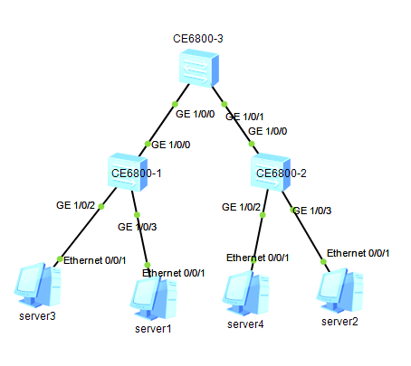
配置基于接口划分VLAN示例


适用产品和版本

CE12800/CE6800/CE5800系列产品V100R001C00或更高版本。


组网需求

如图1所示,数据中心的接入层交换机SwitchA和SwitchB接入到核心层交换机SwitchC,SwitchA和SwitchB连接生产业务服务器和办公业务服务器,其中Server1和Server2属于生产业务服务器,Server3和Server4属于办公业务服务器。

为了通信的安全性,也为了避免广播报文泛滥,管理员希望业务相同的服务器之间可以互通,业务不同的服务器不能互通。


需求分析

可以在SwitchA和SwitchB上配置基于接口划分VLAN,把业务相同的服务器连接的接口划分到同一VLAN中,这样属于不同VLAN内的服务器不能直接进行二层互通,同一VLAN的服务器可以直接进行二层通信。

采用如下的思路配置VLAN:
1.创建VLAN并将连接服务器的接口加入VLAN,实现不同业务之间的二层流量隔离。
2.配置SwitchA和SwitchC、SwitchB和SwitchC之间的链路类型及允许通过的VLAN,实现相同业务通过SwitchC通信。


操作步骤
1.在SwitchA和SwitchB上创建VLAN200和VLAN300,并将相应的接口分别加入VLAN。

# 配置SwitchA
<HUAWEI> system-view
[~HUAWEI] sysname SwitchA
[*HUAWEI] commit
[~SwitchA] vlan batch 200 300
[*SwitchA] interface 10ge 1/0/2
[*SwitchA-10GE1/0/2] port default vlan 200
[*SwitchA-10GE1/0/2] quit
[*SwitchA] interface 10ge 1/0/3
[*SwitchA-10GE1/0/3] port default vlan 300
[*SwitchA-10GE1/0/3] quit
[*SwitchA] interface 10ge 1/0/1
[*SwitchA-10GE1/0/1] port link-type trunk
[*SwitchA-10GE1/0/1] undo port trunk allow-pass vlan 1
[*SwitchA-10GE1/0/1] port trunk allow-pass vlan 200 300
[*SwitchA-10GE1/0/1] quit
[*SwitchA] commit

# 配置SwitchB
<HUAWEI> system-view
[~HUAWEI] sysname SwitchB
[*HUAWEI] commit
[~SwitchB] vlan batch 200 300
[*SwitchB] interface 10ge 1/0/2
[*SwitchB-10GE1/0/2] port default vlan 200
[*SwitchB-10GE1/0/2] quit
[*SwitchB] interface 10ge 1/0/3
[*SwitchB-10GE1/0/3] port default vlan 300
[*SwitchB-10GE1/0/3] quit
[*SwitchB] interface 10ge 1/0/1
[*SwitchB-10GE1/0/1] port link-type trunk
[*SwitchB-10GE1/0/1] undo port trunk allow-pass vlan 1
[*SwitchB-10GE1/0/1] port trunk allow-pass vlan 200 300
[*SwitchB-10GE1/0/1] quit
[*SwitchB] commit


2.配置SwitchA和SwitchC、SwitchB和SwitchC之间的链路类型,并将相应的接口加入VLAN。
<HUAWEI> system-view
[~HUAWEI] sysname SwitchC
[*HUAWEI] commit
[~SwitchC] vlan batch 200 300
[*SwitchC] interface 10ge 1/0/1
[*SwitchC-10GE1/0/1] port link-type trunk
[*SwitchC-10GE1/0/1] undo port trunk allow-pass vlan 1
[*SwitchC-10GE1/0/1] port trunk allow-pass vlan 200 300
[*SwitchC-10GE1/0/1] quit
[*SwitchC] interface 10ge 1/0/2
[*SwitchC-10GE1/0/2] port link-type trunk
[*SwitchC-10GE1/0/2] undo port trunk allow-pass vlan 1
[*SwitchC-10GE1/0/2] port trunk allow-pass vlan 200 300
[*SwitchC-10GE1/0/2] quit
[*SwitchC] commit


验证

将Server1和Server2配置在同一个网段,比如192.168.100.0/24;将Server3和Server4配置在同一个网段,比如192.168.200.0/24。

Server1和Server2能够互相ping通,但是均不能ping通Server3和Server4。Server3和Server4能够互相ping通,但是均不能ping通Server1和Server2。


配置文件

•SwitchA的配置文件
#
sysname SwitchA
#
vlan batch 200 300
#
interface 10GE1/0/1
 port link-type trunk
 undo port trunk allow-pass vlan 1
 port trunk allow-pass vlan 200 300
#
interface 10GE1/0/2
 port default vlan 200
#
interface 10GE1/0/3
 port default vlan 300
#
return


•SwitchB的配置文件
#
sysname SwitchB
#
vlan batch 200 300
#
interface 10GE1/0/1
 port link-type trunk
 undo port trunk allow-pass vlan 1
 port trunk allow-pass vlan 200 300
#
interface 10GE1/0/2
 port default vlan 200
#
interface 10GE1/0/3
 port default vlan 300
#
return


•SwitchC的配置文件
#
sysname SwitchC
#
vlan batch 200 300
#
interface 10GE1/0/1
 port link-type trunk
 undo port trunk allow-pass vlan 1
 port trunk allow-pass vlan 200 300
#
interface 10GE1/0/2
 port link-type trunk
 undo port trunk allow-pass vlan 1
 port trunk allow-pass vlan 200 300
#
return
查询mac地址参考链接
https://zhidao.baidu.com/question/412549257.html
三、dell交换机
文档链接:
https://www.dell.com/support/incidents-online/zh-cn/contactus/Dynamic
https://www.dell.com/support/home/zh-cn/product-support/product/networking-s5248f-on/docs

在 SmartFabric 模式下,PowerEdge MX 交换机作为第二层 I/O 聚合设备运行。OpenManage Enterprise - Modular 界面支持大多数交
换机配置设置。使用 SmartFabric 模式配置您的交换机。
SmartFabric 模式支持所有 OS10 show 命令和以下 CLI 配置命令子集:其他 CLI 配置命令不可用。
• clock — 配置时钟参数。
• end — 退出到 EXEC 模式。
• exit — 退出当前模式
• help — 显示可用命令。
• hostname — 设置系统主机名称。
• interface — 配置管理接口、VLAN 接口或一系列接口。
• ip name-server — 配置名称服务器的 IP 地址;最多支持三个名称服务器。
• logging — 配置系统日志记录。
• management route — 配置 IPv4 或 IPv6 管理路由。
• no — 在配置模式下删除或禁用命令。
• ntp — 配置网络时间协议。
• snmp-server — 配置 SNMP 服务器。
• spanning-tree
• disable — 全局禁用生成树。
• mac-flush-timer — 设置用于刷新 MAC 地址条目的时间。
• mode — 启用生成树模式,如 RSTP 或 MST。
• mst — 配置多个生成树 (MST) 模式。
• rstp — 配置快速生成树协议 (RSTP) 模式。
• vlan — 在 VLAN 范围上配置生成树。
• username — 创建或修改用户凭据。
• SupportAssist — 配置 SupportAssist 相关设置。
• Security — 配置与网络安全对应的功能。
• Fibre Channel — 配置与光纤通道接口对应的功能。

1,登录检查版本
OS10# show version

no
在 EXEC 模式下禁用或删除命令。
语法no [alias | debug | support-assist-activity | terminal]
参数• alias — 移除别名定义。
• debug — 禁用调试。
• support-assist-activity — 与 SupportAssist 相关的活动。
• terminal — 重置终端设置。
默认未配置
命令模式EXEC
使用情况信息在 EXEC 模式下使用此命令可禁用或移除配置。在 CONFIGURATION 模式下使用 no ? 可查看可用的命令。
示例
OS10# no alias goint

两种交换机模式:SmartFabric Mode 和 Full-Switch

交换机模式:
OS10(config)# do show switch-operating-mode

Switch-Operating-Mode : SmartFabric Mode

将交换机设置为全交换
switch-operating mode
将交换机的操作模式设置为 SmartFabric Director 模式。
语法switch-operating-mode Full-Switch
参数• Full-Switch — 将操作模式设置为全交换。
默认未配置
命令模式CONFIGURATION 模式
使用情况信息无。
示例
OS10(config)# switch-operating-mode Full-Switch

以太网接口
默认情况下,以太网端口接口处于启用状态。要禁用以太网接口,请使用 shutdown 命令。使用 show interface status 命令
可查看接口的状况。
要重新启用已禁用的接口,请使用 no shutdown 命令。
1. 在 Global CONFIGURATION 模式下配置以太网端口接口。
interface ethernet node/slot/port[:subport]
2. 在 INTERFACE 模式下禁用并重新启用以太网端口接口。
shutdown
no shutdown
禁用以太网端口接口
OS10(config)# interface ethernet 1/1/1
OS10(conf-if-eth1/1/1)# shutdown
启用以太网端口接口
OS10(config)# interface ethernet 1/1/1
OS10(conf-if-eth1/1/1)# no shutdown

查看端口配置信息
OS10(config)# interface ethernet 1/1/3:2
OS10(conf-if-eth1/1/3:2)# show configuration
!
interface ethernet1/1/3:2
no shutdown

查看交换机端口组
OS10# show port-group

查看L3端口
OS10# show ip interface brief

查看VLAN
OS10# show vlan


1. 配置管理 IP 地址。
2. 配置管理路由。
3. 配置用户名和密码。

一,配置管理 IP 地址
要远程访问 OS10,请向管理端口分配 IP 地址。使用管理接口进行带外 (OOB) 交换机管理。
1. 从 CONFIGURATION 模式配置管理接口。
interface mgmt 1/1/1
2. 默认情况下,DHCP 客户端在管理接口上处于启用状态。在 INTERFACE 模式下禁用 DHCP 客户端操作。
no ip address dhcp
3. 在 INTERFACE 模式下,在管理接口上配置 IPv4 或 IPv6 地址。
ip address A.B.C.D/mask
ipv6 address A:B/prefix-length
4. 在 INTERFACE 模式下启用管理接口。
no shutdown

例如:配置管理接口
OS10(config)# interface mgmt 1/1/1
OS10(conf-if-ma-1/1/1)# no ip address dhcp
OS10(conf-if-ma-1/1/1)# ip address 10.1.1.10/24
OS10(conf-if-ma-1/1/1)# no shutdown

2,查看序列号
OS10#
OS10# show inventory
Product               : S4112F-ON
Description           : S4112F-ON 12x10GbE, 3x100GbE Interface Module
Software version      : 10.5.0.6
Product Base          :
Product Serial Number :
Product Part Number   :

Unit Type                     Part Number  Rev  Piece Part ID             Svc Tag  Exprs Svc Code
-------------------------------------------------------------------------------------------------
* 1  S4112F-ON                0086KK       A00  TW-0086KK-DNG00-08B-0063  7M7KPK2  165 804 557 78
  1  S4112F-ON-PWR-1-AC       NA           NA   NA
  1  S4112F-ON-PWR-2-AC       NA           NA   NA
  1  S4112F-ON-FANTRAY-1-R    NA           NA   NA
二、配置管理路由
要设置 OS10 的远程访问,请在将 IPv4 或 IPv6 地址分配给管理端口后配置管理路由。管理端口使用默认管理路由与其他网络进行通
信。管理路由允许您将管理流量与数据流量分开。
1. (可选)确保在 INTERFACE 模式下的管理接口上禁用了 DHCP 客户端。
no ip address dhcp
2. 在 CONFIGURATION 模式下为管理端口配置管理路由。重复命令以配置多个路由。
management route {ipv4-address/mask | ipv6-address/prefix-length}
{forwarding-router-address | managementethernet}
• ipv4-address/mask — 以点分隔的十进制格式 (A.B.C.D) 输入 IPv4 网络地址,然后以前缀长度格式 (/x) 输入子网掩码。
• ipv6-address/prefix-length — 以 x:x:x:x::x 格式输入 IPv6 地址,前缀长度为 /x 格式。前缀范围是 /0 至 /128。
• forwarding-router-address — 输入转发路由器的下一中继站 IPv4/IPv6 地址,用作连接到不同子网的管理网关。
• managementethernet — 针对配置的 IPv4/IPv6 子网在管理端口上发送流量。
注: 管理路由独立于 IPv4 和 IPv6 路由,前者用于通过管理端口管理交换机。

配置管理路由
OS10(config)# management route 10.10.20.0/24 10.1.1.1
OS10(config)# management route 172.16.0.0/16 managementethernet
OS10(config)# management route 0.0.0.0/0 10.226.26.247
三、配置用户名和密码
要设置对 OS10 的远程访问,在配置管理端口和默认路由后创建用户名和密码。用户角色是必需的条目。
以明文形式输入密码。它会转换为正在运行的配置中的 SHA-512 格式。密码必须包含至少 9 个字符,包括字母数字和特殊字符,以
及以前用于同一用户名的密码中至少有五个不同的字符;例如:
OS10(config)# username admin password alpha404! role sysadmin

为了向后兼容 OS10 版本 10.3.1E 及更低版本,支持以 MD-5、SHA-256 和 SHA-512 格式输入密码。要增加所需的密码强度,请使用
password-attributes 命令。

• 在 CONFIGURATION 模式下创建用户名和密码。
username username password password role role
• username username — 输入文本字符串。最多 32 个字母数字字符;最少 1 个字符。
• password password — 输入文本字符串。最多 32 个字母数字字符;最少 9 个字符。
• role role — 输入用户角色:
• sysadmin — 对系统中所有命令的完全访问权限、对操作文件系统的命令的独占访问权限,以及对系统 shell 的访问权
限。系统管理员可以创建用户 ID 和用户角色。默认权限级别为 15。
• secadmin — 对设置安全策略和系统访问权限的配置命令的完全访问权限,如密码强度、AAA 授权和加密密钥。安全管
理员可以显示安全信息,如加密密钥、登录统计信息和日志信息。默认权限级别为 15。
• netadmin — 对管理流经交换机(如路由、接口和 ACL)的流量的配置命令的完全访问权限。网络管理员无法访问安全
功能的配置命令或查看安全信息。默认权限级别为 15。
• netoperator — EXEC 模式访问,以使用有限的显示命令集。网络操作员无法修改交换机上的任何配置设置。默认权限级别为 1。

注: 要更改系统管理员密码,请使用新密码重新输入管理员用户名的命令。
OS10(config)# username admin password beta@1 role sysadmin


CONFIGURATION 模式
首次登录 OS10 时,您将处于 EXEC 模式。要访问 CONFIGURATION 模式,请输入 configure terminal 命令。使用
CONFIGURATION 模式来管理接口、协议和功能。
OS10# configure terminal
OS10(config)#


例如,在进入事务模式之前,您可以检查是否未输入任何新的配置命令。如果 show 命令未返回输出,则 candidateconfiguration
和 running-configuration 文件是相同的。然后启动事务模式、配置新设置,并查看候选配置与正在运行的
配置之间的差异。确定是否要提交对正在运行的配置的更改。要删除未提交的更改,请使用 discard 命令。
查看候选配置与正在运行的配置之间的差异
OS10# show diff candidate-configuration running-configuration
OS10#
OS10# start transaction
OS10# configure terminal
OS10(config)# interface vlan 100
OS10(conf-if-vl-100)# exit
OS10(config)# interface ethernet 1/1/15
OS10(conf-if-eth1/1/15)# switchport mode trunk
OS10(conf-if-eth1/1/15)# switchport trunk allowed vlan 100
OS10(conf-if-eth1/1/15)# end
OS10# show diff candidate-configuration running-configuration
!
interface ethernet1/1/15
switchport mode trunk
switchport trunk allowed vlan 100
!
interface vlan100
no shutdown
OS10#
在事务模式下的候选配置中提交配置更改
1. 从 EXEC 模式更改为基于事务的配置模式。
start transaction
2. 输入配置命令。例如,从 INTERFACE 模式下启用接口。
interface ethernet 1/1/1
no shutdown
3. 将配置更改保存到正在运行的配置。
do commit
输入 commit 命令后,当前 OS10 会话将切换回自动提交所有配置更改的默认行为。
OS10# start transaction
OS10# configure terminal
OS10(config)#
OS10(config)# interface ethernet 1/1/1
OS10(config-if-eth1/1/1)# no shutdown
OS10(config-if-eth1/1/1)# do commit
4,写入
# do write memory

四、创建VLAN


OS10#
OS10# start transaction  进入事务型,并不是能马上生效,需要提交生效
OS10# configure terminal
OS10(config)# interface vlan 100
OS10(conf-if-vl-100)# exit


五、端口添加VLAN
OS10(config)# interface ethernet 1/1/15
OS10(conf-if-eth1/1/15)# switchport mode trunk
OS10(conf-if-eth1/1/15)# switchport trunk allowed vlan 100
OS10(conf-if-eth1/1/15)# end

六,事务模式
例如,在进入事务模式之前,您可以检查是否未输入任何新的配置命令。如果 show 命令未返回输出,则 candidateconfiguration和 running-configuration 文件是相同的。然后启动事务模式、配置新设置,并查看候选配置与正在运行的配置之间的差异。确定是否要提交对正在运行的配置的更改。要删除未提交的更改,请使用 discard 命令。
OS10# show diff candidate-configuration running-configuration
!
interface ethernet1/1/15
switchport mode trunk
switchport trunk allowed vlan 100
!
interface vlan100
no shutdown
OS10#

在事务模式下的候选配置中提交配置更改
1. 从 EXEC 模式更改为基于事务的配置模式。
start transaction
2. 输入配置命令。例如,从 INTERFACE 模式下启用接口。
interface ethernet 1/1/1
no shutdown
3. 将配置更改保存到正在运行的配置。
do commit
输入 commit 命令后,当前 OS10 会话将切换回自动提交所有配置更改的默认行为。
OS10# start transaction
OS10# configure terminal
OS10(config)#
OS10(config)# interface ethernet 1/1/1
OS10(config-if-eth1/1/1)# no shutdown
OS10(config-if-eth1/1/1)# do commit

七,显示管理端口IPV4的路由
OS10# show ip management-route
Destination Gateway State Source
-----------------------------------------------------------------
192.168.10.0/24 managementethernet Connected Connected

八,显示交换机端口情况
OS10# show interface status

--------------------------------------------------------------------------------------------------
Port            Description     Status   Speed    Duplex   Mode Vlan Tagged-Vlans
--------------------------------------------------------------------------------------------------
Eth 1/1/1                       up       10G      full     T         -
Eth 1/1/2                       down     0        full     T         -
Eth 1/1/3                       up       10G      full     T         -
Eth 1/1/4                       down     0        full     T         -
Eth 1/1/5                       up       10G      full     T         -
Eth 1/1/6                       down     0        full     T         -
Eth 1/1/7                       down     0        full     T         -
Eth 1/1/8                       down     0        full     T         -
Eth 1/1/9                       down     0        full     T         -
Eth 1/1/10                      down     0        full     T         -
Eth 1/1/11                      down     0        full     T         -
Eth 1/1/12                      down     0        full     T         -
Eth 1/1/13                      down     0        full     T         -
Eth 1/1/14                      down     0        full     T         -
Eth 1/1/15                      down     0        full     T         -
--------------------------------------------------------------------------------------------------
九,端口拆分
P298
配置 QSFP28 端口组接口
OS10(config)# port-group 1/1/13
OS10(conf-pg-1/1/13)# mode Eth 25g-4x
OS10(conf-pg-1/1/13)# exit

100G口拆分成10G-8x
OS10(config)# port-group 1/1/13
OS10(conf-pg-1/1/13)# show configuration
!
port-group 1/1/13
 mode Eth 100g-2x
OS10(conf-pg-1/1/13)# mode Eth
100g-2x 50g-4x  40g-2x  10g-8x  25g-8x
OS10(conf-pg-1/1/13)# mode Eth 1
100g-2x 10g-8x
OS10(conf-pg-1/1/13)# mode Eth 10g-8x
OS10(conf-pg-1/1/13)#
OS10(conf-pg-1/1/13)#
OS10(conf-pg-1/1/13)# show configuration
!
port-group 1/1/13
 mode Eth 10g-8x


十、动态LACP
https://www.dell.com/support/kbdoc/zh-cn/000121857/%e5%a6%82%e4%bd%95%e5%9c%a8dell-networking-powerconnect%e4%ba%a4%e6%8d%a2%e6%9c%ba%e4%b8%8a%e5%88%9b%e5%bb%ba%e9%93%be%e8%b7%af%e8%81%9a%e5%90%88%e7%bb%84-lag
2017年:
https://www.xuexila.com/diannao/diy/2870911.html


P240 官方文档
LACP 使端口可动态捆绑为端口通道的成员。要配置 LACP 操作的端口,请使用 channel-group mode {active|passive} 命令。主动和被动模式允许 LACP 在端口之间进行协商,以确定是否可以根据配置设置来形成端口通道。

进入全局模式
OS10(config)#
创建聚合组并进入聚合接口模式
OS10(config)# interface port-channel 100
OS10(conf-if-po-100)# exit
将端口1/1/2加入聚合组100并指定聚合模式为active
OS10(config)# interface ethernet 1/1/2
OS10(conf-if-eth1/1/2)# channel-group 100 mode active
聚合接口下进行端口配置(聚合接口端口模式)
interface ethernet1/1/15
switchport mode trunk
switchport trunk allowed vlan 151

删除端口通道
OS10(config)# interface port-channel 10
OS10(conf-if-po-10)# no interface port-channel 10

如何验证端口通道状态
console# show interfaces port-channel 1


十一、开发测试isilon 前端25G交换机配置
#show run
(1)查看接口情况
OS10(conf-if-eth1/1/56)# do show interface status

--------------------------------------------------------------------------------------------------
Port            Description     Status   Speed    Duplex   Mode Vlan Tagged-Vlans
--------------------------------------------------------------------------------------------------
Eth 1/1/1                       down     0        full     A    1581 -
Eth 1/1/2                       up       25G      full     A    1581 -
Eth 1/1/3                       up       25G      full     A    1581 -
Eth 1/1/4                       up       25G      full     A    1581 -
Eth 1/1/5                       up       25G      full     A    1581 -
Eth 1/1/6                       up       25G      full     A    1581 -
Eth 1/1/7                       down     0        full     A    1    -
Eth 1/1/8                       down     0        full     A    1    -
Eth 1/1/9                       down     0        full     A    1    -

。。。。。。。。
Eth 1/1/44                      down     0        full     A    1    -
Eth 1/1/45                      down     0        full     A    1    -
Eth 1/1/46                      down     0        full     A    1    -
Eth 1/1/47                      down     0        full     A    1    -
Eth 1/1/48                      down     0        full     A    1    -
Eth 1/1/49                      down     0        full     A    1    -
Eth 1/1/50                      down     0        full     A    1    -
Eth 1/1/51                      down     0        full     A    1    -
Eth 1/1/52                      down     0        full     A    1    -
Eth 1/1/53                      down     0        full     -
Eth 1/1/54                      down     0        full     -
Eth 1/1/55                      down     0        full     -
Eth 1/1/56                      down     0        full     -

#因为接口Eth 1/1/53-1/1/56是100G端口,而实际接的是40G线缆

(2)查看端口组情况
OS10(conf-if-eth1/1/56)# do show port-group

Port-group            Mode           Ports     FEM
port-group1/1/1       Eth 25g-4x     1  2  3  4     -
port-group1/1/2       Eth 25g-4x     5  6  7  8     -
port-group1/1/3       Eth 25g-4x     9  10  11  12     -
port-group1/1/4       Eth 25g-4x     13  14  15  16     -
port-group1/1/5       Eth 25g-4x     17  18  19  20     -
port-group1/1/6       Eth 25g-4x     21  22  23  24     -
port-group1/1/7       Eth 25g-4x     25  26  27  28     -
port-group1/1/8       Eth 25g-4x     29  30  31  32     -
port-group1/1/9       Eth 25g-4x     33  34  35  36     -
port-group1/1/10      Eth 25g-4x     37  38  39  40     -
port-group1/1/11      Eth 25g-4x     41  42  43  44     -
port-group1/1/12      Eth 25g-4x     45  46  47  48     -
port-group1/1/13      Eth 100g-2x    49  50     -
port-group1/1/14      Eth 100g-2x    51  52     -
port-group1/1/15      Eth 100g-1x    53         -
port-group1/1/16      Eth 100g-1x    54         -
port-group1/1/17      Eth 100g-1x    55         -
port-group1/1/18      Eth 100g-1x    56         -
#port-group1/1/15-1/1/18对应端口是Eth1/1/53-1/1/56模式是100g-1x,这里需要修改模式为40g-1x

(3)修改端口组mode
#port-group1/1/15-1/1/18需要修改模式为40g-1x

OS10(config)# port-group 1/1/18
OS10(conf-pg-1/1/18)# show configuration
!
port-group 1/1/18
 mode Eth 100g-1x
OS10(conf-pg-1/1/18)#
OS10(conf-pg-1/1/18)# mode Eth
100g-1x 50g-2x  40g-1x  25g-4x  10g-4x
OS10(conf-pg-1/1/18)# mode Eth 40g-1x
OS10(conf-pg-1/1/18)#
OS10(conf-pg-1/1/18)#
OS10(conf-pg-1/1/18)# show configuration
candidate |
OS10(conf-pg-1/1/18)# show configuration
!
port-group 1/1/18
 mode Eth 40g-1x
OS10(conf-pg-1/1/18)#do write
#分别把剩余的3个端口组修改成40g
OS10(config)# do show port-group

Port-group            Mode           Ports     FEM
port-group1/1/1       Eth 25g-4x     1  2  3  4     -
port-group1/1/2       Eth 25g-4x     5  6  7  8     -
port-group1/1/3       Eth 25g-4x     9  10  11  12     -
port-group1/1/4       Eth 25g-4x     13  14  15  16     -
port-group1/1/5       Eth 25g-4x     17  18  19  20     -
port-group1/1/6       Eth 25g-4x     21  22  23  24     -
port-group1/1/7       Eth 25g-4x     25  26  27  28     -
port-group1/1/8       Eth 25g-4x     29  30  31  32     -
port-group1/1/9       Eth 25g-4x     33  34  35  36     -
port-group1/1/10      Eth 25g-4x     37  38  39  40     -
port-group1/1/11      Eth 25g-4x     41  42  43  44     -
port-group1/1/12      Eth 25g-4x     45  46  47  48     -
port-group1/1/13      Eth 100g-2x    49  50     -
port-group1/1/14      Eth 100g-2x    51  52     -
port-group1/1/15      Eth 40g-1x     53         -
port-group1/1/16      Eth 40g-1x     54         -
port-group1/1/17      Eth 40g-1x     55         -
port-group1/1/18      Eth 40g-1x     56         -

(4)1/1/53-1/1/56四个口一起,创建聚合。
interface port-channel101
 no shutdown
 switchport mode trunk
 switchport access vlan 1
 switchport trunk allowed vlan 1581
!
(5)将端口加入聚合
将端口1/1/56加入聚合组100并指定聚合模式为active
OS10(config)# interface ethernet 1/1/56
OS10(conf-if-eth1/1/2)# channel-group 101 mode active
#查看接口配置
OS10(config)# interface range ethernet 1/1/53:1-1/1/56:1
OS10(conf-range-eth1/1/53:1-1/1/56:1)# show configuration
!
interface ethernet1/1/53:1
 no shutdown
 channel-group 101 mode active
 no switchport
!
interface ethernet1/1/54:1
 no shutdown
 channel-group 101 mode active
 no switchport
!
interface ethernet1/1/55:1
 no shutdown
 channel-group 101 mode active
 no switchport
!
interface ethernet1/1/56:1
 no shutdown
 channel-group 101 mode active
 no switchport

#查看聚合
OS10(config)# do show port-channel summary

Flags:  D - Down    I - member up but inactive    P - member up and active
        U - Up (port-channel)    F - Fallback Activated
--------------------------------------------------------------------------------
Group Port-Channel           Type     Protocol  Member Ports
--------------------------------------------------------------------------------
101  port-channel101  (U)     Eth      DYNAMIC   1/1/53:1(P) 1/1/54:1(P) 1/1/55:1(P) 1/1/56:1(P)
#查看端口聚合详细情况
OS10(config)# do show interface port-channel 101
Port-channel 101 is up, line protocol is up
Address is c0:3e:ba:dc:96:66, Current address is c0:3e:ba:dc:96:66
Interface index is 72
Internet address is not set
Mode of IPv4 Address Assignment: not set
Interface IPv6 oper status: Disabled
MTU 1532 bytes, IP MTU 1500 bytes
LineSpeed 160G
Minimum number of links to bring Port-channel up is 1
Maximum active members that are allowed in the portchannel is 32
Members in this channel: Eth 1/1/53:1,1/1/54:1,1/1/55:1,1/1/56:1
ARP type: ARPA, ARP Timeout: 60
Last clearing of "show interface" counters: 18:27:32
Queuing strategy: fifo
Input statistics:
     10238403 packets, 5889803145 octets
     1 64-byte pkts, 5860144 over 64-byte pkts, 758952 over 127-byte pkts
     188879 over 255-byte pkts, 56868 over 511-byte pkts, 3373559 over 1023-byte pkts
     3617790 Multicasts, 2728424 Broadcasts, 3891232 Unicasts
     0 runts, 0 giants, 0 throttles
     0 CRC, 0 overrun, 0 discarded
Output statistics:
     459621 packets, 34483187 octets
     4592 64-byte pkts, 439744 over 64-byte pkts, 7580 over 127-byte pkts
     7694 over 255-byte pkts, 9 over 511-byte pkts, 2 over 1023-byte pkts
     75491 Multicasts, 33 Broadcasts, 384097 Unicasts
     0 throttles, 0 discarded, 0 Collisions,  wred drops
Rate Info(interval  seconds):
     Input 0 Mbits/sec, 101 packets/sec, 0% of line rate
     Output 0 Mbits/sec, 4 packets/sec, 0% of line rate
Time since last interface status change: 15:28:34
四、联想交换机
文档: https://systemx.lenovofiles.com/help/index.jsp?topic=%2Fcom.lenovo.rackswitch.g8272.doc%2Frs_g8272.html&cp=0_4_5 Pwd2020x0x0x0x7x3 一、配置管理口 Using the Switch Management Ports To manage the switch through the management ports, you must configure an IP interface for each management interface. Configure the following IPv4 parameters: IP address/mask Default gateway address 1. Log on to the switch. 2. Enter Global Configuration mode. RS 8272> enable RS 8272# configure terminal 3. Configure a management IP address and mask: RS 8272(config)# interface ip 128 RS 8272(configipif)# ip address <management interface IPv4 address> RS 8272(configipif)# ip netmask <IPv4 subnet mask> RS 8272(configipif)# enable RS 8272(configipif)# exit 4. Configure the appropriate default gateway. IP gateway 4 is required for IF 128. RS 8272(config)# ip gateway 4 address <default gateway IPv4 address> RS 8272(config)# ip gateway 4 enable 二、基础命令 1,查看端口状态 lenovoG8272-003#show interface status ----------------------------------------------------------------------- Port Speed Duplex Flow Ctrl Link Description ------- ------ -------- --TX-----RX-- ------ ------------- 1 10000* full* no* no* down 1 2 1G/10G full no no down 2 3 1G/10G full no no down 3 4 1G/10G full no no down 4 5 1G/10G full no no down 5 2,查看运行配置 lenovoG8272-003#show running-config Current configuration: ! version "8.4.19" switch-type "Lenovo RackSwitch G8272" 3,创建VLAN 创建VLAN 101 lenovoG8272-003(config)#vlan 101 Warning: VLAN 101 was assigned to STG 101. VLAN 101 is created. Access Mode Port RS 8272(config)# interface port <port number> RS 8272(configif)# switchport access vlan <VLAN ID> For Trunk Mode Port RS 8272(config)# interface port <port number> RS 8272(configif)# switchport trunk native vlan <VLAN ID> # 设置接口access 3,Configure server ports that belong to a single VLAN. RS 8272(config)# interface port 4 RS 8272(configif)#switchport mode access RS 8272(configif)#switchport access vlan 2 RS 8272(configif)#exit 设置接口vlan #switchport mode trunk 1. Enable VLAN tagging/trunk mode on server ports that support multiple VLANs. RS 8272(config)# interface port 5 RS 8272(configif)#switchport mode trunk RS 8272(configif)#switchport trunk allowed vlan add 2 RS 8272(configif)#exit 2,Enable tagging/trunk mode on uplink ports that support multiple VLANs. RS 8272(config)# interface port 19 RS 8272(configif)#switchport mode trunk RS 8272(configif)#switchport trunk allowed vlan add 2,3 RS 8272(configif)#exit RS 8272(config)# interface port 20 RS 8272(configif)#switchport mode trunk RS 8272(configif)#switchport trunk allowed vlan add 2,3 RS 8272(configif)#exit 4,LACP(Link Aggregation Control Protocol) P138 查看lacp RS 8272 # show lacp information LACP Port Modes off(默认)、active、 配置Configuring LACP Use the following procedure to configure LACP for ports 7, 8, 9 and 10 toparticipate in link aggregation. 1. Configure port parameters. All ports that participate in the LACP trunk group must have the same settings, including VLAN membership. 2. Select the port range and define the admin key. Only ports with the same admin key can form an LACP trunk group. RS 8272(config)# interface port 710 RS 8272(configif)#lacp key 100 3. Set the LACP mode. RS 8272(configif)#lacp mode active 4. Allow member ports to individually participate in normal data traffic if no LACPDUs are received. RS 8272(configif)#no lacp suspendindividual RS 8272(configif)#exit 5. Set the link aggregation as static, by associating it with trunk ID 65: RS 8272(config)# interface port <port number or range> RS 8272(configif)#portchannel minlinks <minimum links> RS 8272(configif)#exit RS 8272(config)# interface portchannel lacp <LACP key> RS 8272(configPortChannel)#portchannel minlinks <minimum links> RS 8272(configif)#exit RS 8272(config)# interface port 710 RS 8272(configif)#lacp key 100 RS 8272(configif)#lacp mode active RS 8272(configif)#no lacp suspendindividual RS 8272(configif)#exit RS 8272(config)# portchannel 65 lacp key 100
五、H3C交换机(聚合配置)
(1) 同一台交换机聚合
  1 1,显示端口情况
  2 <SZYT01PDSWH361>dis interface brief
  3 Brief information on interfaces in route mode:
  4 Link: ADM - administratively down; Stby - standby
  5 Protocol: (s) - spoofing
  6 Interface            Link Protocol Primary IP        Description
  7 InLoop0              UP   UP(s)    --
  8 MGE0/0/0             DOWN DOWN     --
  9 MGE0/0/1             DOWN DOWN     --
 10 NULL0                UP   UP(s)    --
 11 REG0                 UP   --       --
 12 Vlan1                DOWN DOWN     --
 13 Vlan10               UP   UP       10.226.24.41
 14
 15 Brief information on interfaces in bridge mode:
 16 Link: ADM - administratively down; Stby - standby
 17 Speed: (a) - auto
 18 Duplex: (a)/A - auto; H - half; F - full
 19 Type: A - access; T - trunk; H - hybrid
 20 Interface            Link Speed     Duplex Type PVID Description
 21 BAGG100              UP   200G(a)   F(a)   T    1    To_10.226.24.7_group2
 22 BAGG200              DOWN auto      A      A    1
 23 BAGG201              DOWN auto      A      A    1    H3C X10000_stor
 24 BAGG202              DOWN auto      A      A    1    H3C X10000 stor
 25 BAGG203              DOWN auto      A      A    1    H3C X10000_stor
 26 BAGG204              DOWN auto      A      A    1    H3C X10000_stor
 27 BAGG301              UP   50G(a)    F(a)   A    1582 aliyun-storage-cpfs
 28 BAGG302              UP   50G(a)    F(a)   A    1582 aliyun-storage-cpfs
 29 HGE1/0/25            UP   100G(a)   F(a)   T    1
 30 HGE1/0/26            UP   100G(a)   F(a)   T    1
 31
 32 2,查看mac地址
 33 <SZYT01PDSWH361>dis mac-address
 34 MAC Address      VLAN ID    State            Port/Nickname            Aging
 35 0000-0c9f-f00a   10         Learned          BAGG100                  Y
 36 0001-e8d6-1998   10         Learned          BAGG100                  Y
 37 0001-ff0d-0a5c   10         Learned          BAGG100                  Y
 38 000a-f74c-9948   10         Learned          BAGG100                  Y
 39 000a-f792-6c98   10         Learned          BAGG100                  Y
 40
 41 3,查看配置
 42 <SZYT01PDSWH361>dis current-configuration
 43
 44 4,显示某个端口配置
 45 [SZYT01PDSWH361-Twenty-FiveGigE1/0/1]dis th
 46 #
 47 interface Twenty-FiveGigE1/0/1
 48  port link-mode bridge
 49  port access vlan 1000
 50  stp edged-port
 51
 52 5,显示聚合配置mac 地址
 53 [SZYT01PDSWH361]dis link-aggregation summary
 54 Aggregation Interface Type:
 55 BAGG -- Bridge-Aggregation, BLAGG -- Blade-Aggregation, RAGG -- Route-Aggregation, SCH-B -- Schannel-Bundle
 56 Aggregation Mode: S -- Static, D -- Dynamic
 57 Loadsharing Type: Shar -- Loadsharing, NonS -- Non-Loadsharing
 58 Actor System ID: 0x8000, 083a-38fd-7a26
 59
 60 AGG        AGG   Partner ID              Selected  Unselected  Individual  Share
 61 Interface  Mode                          Ports     Ports       Ports       Type
 62 --------------------------------------------------------------------------------
 63 BAGG100    D     0x8000, 6ce5-f779-6b11  2         0           0           Shar
 64
 65 6,配置服务器bond4聚合链路和交换机聚合端口案例
 66 服务器侧:bond4
 67 交换机侧:
 68 先配置
 69 interface Bridge-Aggregation101
 70  link-aggregation mode dynamic
 71
 72 然后进入端口配置加入到聚合101
 73 interface Twenty-FiveGigE1/0/40
 74  port link-mode bridge(删不掉的,一直存在)
 75  port link-aggregation group 101
 76
 77 再次进入聚合101,配置(只能用access,不能用trunk,可能原因是一台接入交换)
 78 interface Bridge-Aggregation101
 79 port access vlan 1000
 80
 81 端口配置变成
 82 interface Twenty-FiveGigE1/0/40
 83  port link-mode bridge
 84  port access vlan 1000
 85  port link-aggregation group 101
 86 #
 87
 88 7,接入和汇聚聚合端口
 89 interface Bridge-Aggregation100
 90  description To_group2
 91  port link-type trunk
 92  undo port trunk permit vlan 1
 93  port trunk permit vlan 10 1500 to 1502
 94  link-aggregation mode dynamic
 95
 96
 97 #
 98 interface HundredGigE1/0/25
 99  port link-mode bridge
100  port link-type trunk
101  undo port trunk permit vlan 1
102  port trunk permit vlan 10 1500 to 1502
103  port link-aggregation group 100
104 #
105 interface HundredGigE1/0/26
106  port link-mode bridge
107  port link-type trunk
108  undo port trunk permit vlan 1
109  port trunk permit vlan 10 1500 to 1502
110  port link-aggregation group 100
(2) 两台交换机配置(lacp聚合配置)
interface  Bridge-Aggregation42
port  access  vlan  1001
link-aggregation mode dynamic
port  drni  group 42
stp  edged-port


dis  link-aggregation  v  b  42
(3) 服务器侧 Centos6/7多网卡配置端口聚合
bond=4
 1 linux系统下bond mode参数说明:
 2 mode=4 在交换机支持LACP时推荐使用,其能提供更好的性能和稳定性
 3 mode=0
 4 轮询模式,所绑定的网卡会针对访问以轮询算法进行平分。
 5 mode=1
 6 高可用模式,运行时只使用一个网卡,其余网卡作为备份,在负载不超过单块网卡带宽或压力时建议使用。
 7
 8 mode=2
 9
10 基于HASH算法的负载均衡模式,网卡的分流按照xmit_hash_policy的TCP协议层设置来进行HASH计算分流,使各种不同处理来源的访问都尽量在同一个网卡上进行处理。
11
12 mode=3
13 广播模式,所有被绑定的网卡都将得到相同的数据,一般用于十分特殊的网络需求,如需要对两个互相没有连接的交换机发送相同的数据。
14
15 mode=4
16
17 802.3ab负载均衡模式,要求交换机也支持802.3ab模式,理论上服务器及交换机都支持此模式时,网卡带宽最高可以翻倍(如从1Gbps翻到2Gbps)
18
19 mode=5
20
21 适配器输出负载均衡模式,输出的数据会通过所有被绑定的网卡输出,接收数据时则只选定其中一块网卡。如果正在用于接收数据的网卡发生故障,则由其他网卡接管,要求所用的网卡及网卡驱动可通过ethtool命令得到speed信息。
22
23 mode=6
24
25 适配器输入/输出负载均衡模式,在”模式5″的基础上,在接收数据的同时实现负载均衡,除要求ethtool命令可得到speed信息外,还要求支持对网卡MAC地址的动态修改功能。
26
27 miimon
28
29 指定MII链路监控频率,单位是毫秒(ms)。这将决定驱动检查每个slave链路状态频率。0表示禁止MII链路监控。100可以作为一个很好的初始参 考值。
30
31 ############
32 Centos6/7多网卡配置端口聚合
33 1. 关闭NetworkManager服务
34 systemctl stop NetworkManager
35 systemctl disable NetworkManager
36
37 2. 加载bond模块
38 modprobe bonding miimon=100 mode=0
39 echo "alias bond0 bonding" >>/etc/modprobe.d/bond.conf
40 echo "options bond0 miimon=100 mode=0" >> /etc/modprobe.d/bond.conf
41
42 3. 配置网卡文件,以网卡eth0、eth1做端口聚合为例
43 创建网卡bond0的配置文件
44 vim /etc/sysconfig/network-scripts/ifcfg-bond0
45 # 添加以下配置,IP地址、掩码、网关按实际填写
46 DEVICE=bond0
47 BOOTPROTO=static
48 USERCTL=no
49 ONBOOT=yes
50 TYPE=Bond
51 BONDING_MASTER=yes
52 BONDING_OPTS="mode=0 miimon=100"
53 IPADDR=10.42.31.1
54 NETMASK=255.255.255.0
55 GATEWAY=10.42.31.1
56
57 #修改网卡eth0的配置文件
58 vim /etc/sysconfig/network-scripts/ifcfg-eth0
59 DEVICE=eth0
60 ONBOOT=yes
61 BOOTPROTO=none
62 USERCTL=no
63 MASTER=bond0
64 SLAVE=yes
65
66 #修改网卡eth1的配置文件
67 vim /etc/sysconfig/network-scripts/ifcfg-eth1
68 DEVICE="eth1"
69 BOOTPROTO="none"
70 ONBOOT="yes"
71 USERCTL=no
72 MASTER=bond0
73 SLAVE=yes
74 4. 重启网络服务,确认网络是网卡速率;
75 systemctl restart network
76 ethtool bond0
nmcli device status eth0
nmcli connection delete

创建team1,并选择模式,centos7以后的模式选择发生了变化,只需写到字典里面即可。
nmcli connection add con-name team1 type team ifname team1 config '{"device": "team1", "runner": {"name": "loadbalance","tx_hash": ["eth", "ipv4", "ipv6"],"tx_balancer": {"name": "basic"}}}'   # 这里选择的是主动模式


添加网卡进行绑定
nmcli connection add con-name team1-port1 type team-slave ifname enp194s0f0 master team1
nmcli connection add con-name team1-port2 type team-slave ifname enp194s0f1 master team1


# 给bond设置IP地址
nmcli connection modify team1 ipv4.addresses 10.176.10.78/24 ipv4.gateway 10.176.11.247 ipv4.method manual

nmcli connection up team1 # 启用team1

重启网络
systemctl restart network  #可以省略

查看状态
teamdctl team1 state

# 列出team1的端口
 teamnl team0 ports
六、H3C交换机配置镜像(场景 防火墙)
大概的是两个端口, 一个端口是监听端口接防火墙,一个是源端口接汇聚
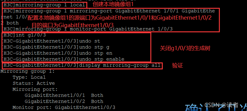
配置步骤: 1. 进入配置模式:system-view 2. 展示所有网口:Display interface brief 3. 设置端口镜像: 创建本地镜像组:mirroring-group 1 local 为镜像组配置源端口: mirroring-group 1 mirroring-port XGE1/0/50 both 备注: XGE1/0/50 配置实际接口 both,全部流量; inbound,入方向流量; outbound,出方向流量。 这里我们选择了both 4. 镜像组配置观察端口 mirroring-group 1 monitor-port XGE1/0/51 XGE1/0/51 配置为实际接口
[SZYT01PDSWH347]mirroring-group 1 monitor-port XGE1/0/7
[SZYT01PDSWH347]dis mirroring-group all
Mirroring group 1:
Type: Local
Status: Active
Mirroring port:
Bridge-Aggregation100 Both
Monitor port: Ten-GigabitEthernet1/0/7
七,华为接入交换机和服务器之间的配置bond1,bond4
一、服务器两网卡如果做的是配置物理(绑定)端口IP地址-意思bond配置不带vlan标记
 1、服务器侧-mode1(主备模式)
DEVICE=eth0
BOOTPROTO=none
ONBOOT=yes
MASTER=bond0
SLAVE=yes
USERCTL=no
NM_CONTROLLED=no

DEVICE=eth1
BOOTPROTO=none
ONBOOT=yes
MASTER=bond0
SLAVE=yes
USERCTL=no
NM_CONTROLLED=no

DEVICE=bond0
IPADDR=192.10.40.41
NETMASK=255.255.255.0
ONBOOT=yes
BOOTPROTO=none
USERCTL=no
TYPE=Bonding
MTU=1500
GATEWAY=192.10.40.254
DEFROUTE=yes
NM_CONTROLLED=no
BONDING_OPTS='mode=1 miimon=100 lacp_rate=fast arp_validate=0 xmit_hash_policy=layer3+4'

交换机侧:
interface GE1/0/1
port link-type access
port default vlan 10

interface GE2/0/1
port link-type access
port default vlan 10

2、服务器侧-mode4
 上述ifcfg-bond0中的配置改成mode=4即可
交换机侧:
配置成Eth-Trunk模式
interface eth-trunk 10
port link-type access
port default vlan 10

interface 10GE1/0/1
eth-trunk 10

interface 10GE2/0/1
eth-trunk 10

二、服务器两网卡如果做的是配置配置物理(绑定)端口IP地址和VLAN-意思bond配置vlan标签
 1、服务器侧-mode2(主备模式)
DEVICE=eth0
BOOTPROTO=none
ONBOOT=yes
MASTER=bond0
SLAVE=yes
USERCTL=no
NM_CONTROLLED=no

DEVICE=eth1
BOOTPROTO=none
ONBOOT=yes
MASTER=bond0
SLAVE=yes
USERCTL=no
NM_CONTROLLED=no

DEVICE=bond0
IPADDR=192.10.40.41
NETMASK=255.255.255.0
ONBOOT=yes
BOOTPROTO=none
USERCTL=no
TYPE=Bonding
MTU=1500
GATEWAY=192.10.40.254
DEFROUTE=yes
NM_CONTROLLED=no
BONDING_OPTS='mode=2 miimon=100 lacp_rate=fast arp_validate=0 xmit_hash_policy=layer3+4'

交换机侧:
interface eth-trunk 10
port link-type trunk
port trunk allow-pass vlan X、Y
undo port trunk allow-pass vlan 1

interface 10GE1/0/1
eth-trunk 10

interface 10GE2/0/1
eth-trunk 10

2、服务器侧-mode4
 上述ifcfg-bond0中的配置改成mode=4即可
交换机侧:
配置成Eth-Trunk模式
interface eth-trunk 10
port link-type trunk
port trunk allow-pass vlan X、Y
undo port trunk allow-pass vlan 1
mode lacp-static
lacp timeout fast

interface 10GE1/0/1
eth-trunk 10

interface 10GE2/0/1
eth-trunk 10