// a 3-input look-up-table

// In this question, you will design a circuit for an 8x1 memory,
// where writing to the memory is accomplished by shifting-in bits,
// and reading is "random access", as in a typical RAM.
// You will then use the circuit to realize a 3-input logic function.
// First, create an 8-bit shift register with 8 D-type flip-flops. D触发器
// Label the flip-flop outputs from Q[0]...Q[7]. The shift register input should be called S,
// which feeds the input of Q[0] (MSB is shifted in first).
//  The enable input controls whether to shift.
//  Then, extend the circuit to have 3 additional inputs A,B,C and an output Z.
//  The circuit's behaviour should be as follows:
//   when ABC is 000, Z=Q[0], when ABC is 001, Z=Q[1], and so on.
//   Your circuit should contain ONLY the 8-bit shift register,
// and multiplexers. (Aside: this circuit is called a 3-input look-up-table (LUT)).

module top_module (
    input clk,
    input enable,
    input S,
    input A, B, C,
    output reg Z );

    reg [7:0] Q;
    always @(posedge clk) begin
        if(enable)begin
            Q <= {Q[6:0],S};
        end
        else Q <=Q;
    end

    always @(*) begin
        case ({A,B,C})
            3'b000: Z = Q[0];
            3'b001: Z = Q[1];
            3'b010: Z = Q[2];
            3'b011: Z = Q[3];
            3'b100: Z = Q[4];
            3'b101: Z = Q[5];
            3'b110: Z = Q[6];
            3'b111: Z = Q[7];
        endcase
    end
endmodule
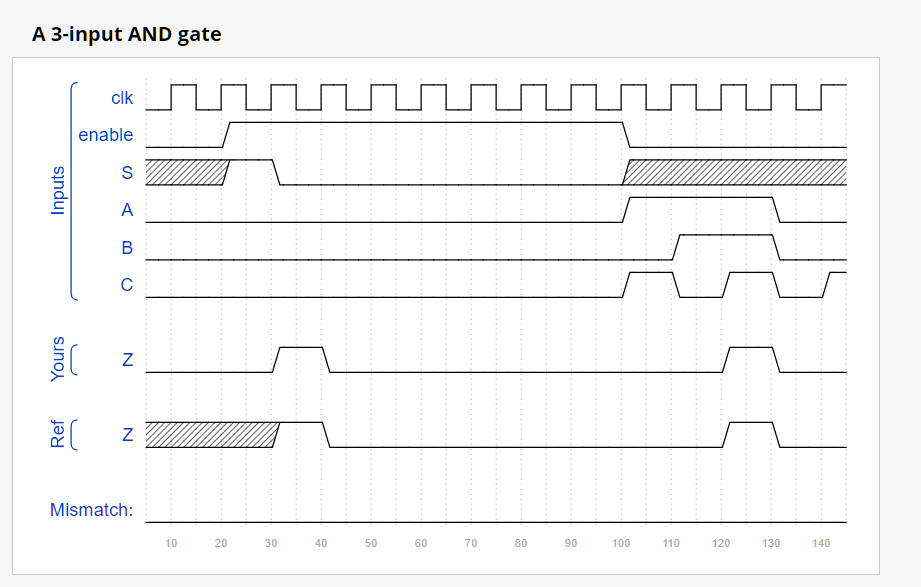
测试结果

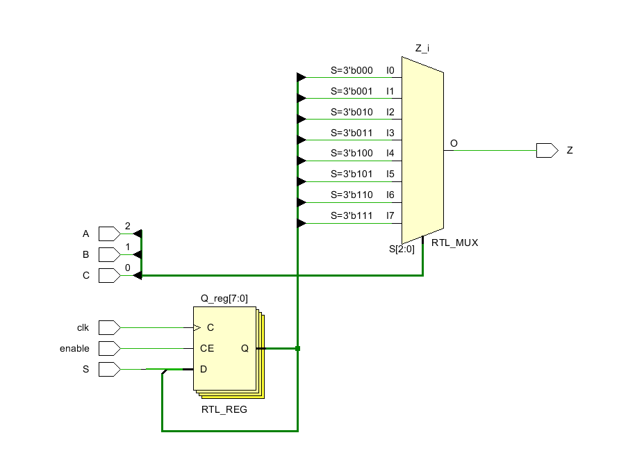
RTL原理图


