CH9121网络串口透传模块STM32驱动
CH9121串口转以太网模块STM32驱动
0. 简介
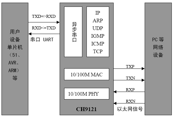
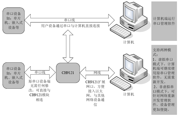
CH9121 集成TCP/IP 协议栈,可实现网络数据包和串口数据的双向透明传输,具有TCPCLIENT、TCP SERVER、UDP 3 种工作模式,串口波特率最高可支持到921600bps,可通过上位机软件轻松配置,方便快捷。
下图为CH9121 应用框图:

1. 特性:
内部自带以太网介质传输层(MAC)和物理层(PHY)。
实现串口数据和网络数据的双向透明传输。
支持10/100M,全双工/半双工自适应以太网接口,兼容IEEE 802.3 协议。
支持MDI/MDIX 线路自动转换。
工作模式支持TCP CLIENT、TCP SERVER 和UDP 模式。
串口波特率支持300bps ~ 921600bps。
串口TTL 电平,兼容3.3V 和5V。
串口支持全双工和半双工串口通讯,支持RS485 收发自动切换。
工作模式、端口、IP 等网络参数,串口波特率等参数可通过上位机配置。
支持虚拟串口。
2. 应用场合

3. 示例平台
STM32F407
4. 代码
bsp_ch9121.h
// 定义了与网络CH9121通信的基本数据结构,和配置结构,参数等
#ifndef __BSP_CH9121_H__
#define __BSP_CH9121_H__

#include <bsp.h>

// 本程序中默认模块做为客户端
#define M_UARTX				UART4

#define WRITE_CMD           {Usartx_SendByte(M_UARTX, 0x57);Usartx_SendByte(M_UARTX, 0xab);}


// 定义接收和发送缓冲区,用动态申请大小,打包长度小于1024byte
extern uint8_t net_tx_buf[1024];
extern uint8_t net_rx_buf[1024];
extern uint8_t overflow_flag;
// 网络连接状态类型
typedef enum _ConnectStatus
{
	disconnect = 0,
	connect_ok
} ConnectStatus;

// 校验方式数据类型
typedef enum _Serial_Check
{
	Even_Check = 0,
	Odd_Check,
	Mark,
	Space,
	None
} Serial_Check;

// 工作模式类型
typedef enum _Net_Mode
{
	TCP_Server_mode = 0,
	TCP_Client_mode,
	UDP_Server_mode,
	UDP_Client_mode
} Net_Mode;

// 服务器/客户端通信相关的类型
typedef struct _Net_CommunitionType
{
	uint16_t port_num;			// 端口号
	uint8_t ip_address[4];			// IP地址
	uint8_t subnet_mask[4];			// 子网掩码
	uint8_t gateway[4];			// 默认网关
        uint16_t tcp_retry_count;		// TCP重试次数
	uint8_t mac_address[4];			// MAC地址
	ConnectStatus status;			// 连接状态
    Net_Mode net_mode;
} Net_CommunitionType;
extern Net_CommunitionType net_communition_Client;
extern Net_CommunitionType net_communition_DstServer;
extern Net_CommunitionType net_communition_Server1;

// 串口相关数据类型
typedef struct _Serial
{
	uint32_t bound;		    // 波特率
	Serial_Check serial_check;  // 校验类型
	uint8_t data_bit;	    // 数据位数
	uint8_t stop_bit;	    // 停止位
	uint32_t timeout;	    // 超时时间
} Serial;
extern Serial serial;


// 写命令码,格式(0x57 0xab + 命令码 + 数据)
#define RESET_CHIP			0x02		// 复位命令,芯片重新运行
#define UPDATE_CONFIG			0x0d		// 更新配置参数至 EEPROM
#define CMD_EXECUTION			0x0e		// 命令执行
#define SET_CHIP_MODE			0x10		// 设置模式
#define SET_CHIP_IP			0x11		// 设置芯片 IP 地址
#define SET_CHIP_SUBNET_MASK	        0x12		// 设置芯片掩码
#define SET_CHIP_GATEWAY		0x13		// 设置芯片网关
#define SET_LOCAL_PORT			0x14		// 设置芯片本地端口
#define SET_DESTINATION_IP		0x15		// 设置芯片目的 IP 地址
#define SET_DESTINATION_PORT	        0x16		// 设置芯片目的端口
#define SET_SERIAL_BOUND		0x21		// 设置串口波特率
#define SET_SERIAL_DATA_FORMAT	        0x22		// 设置串口校验位数据位停止位
#define EXIT_SERIAL_CONFIG		0x5e		// 退出串口配置模式

// 读命令码,格式(0x57 0xab + 命令码)
#define READ_CHIP_MODE			0x60		// 读取芯片工作模式,返回 1 字节
#define READ_CHIP_IP			0x61		// 读取芯片 IP 地址,返回 4 字节
#define READ_CHIP_SUBNET_MASK	        0x62		// 读取芯片掩码,返回 4 字节
#define READ_CHIP_GATEWAY		0X63		// 读取芯片网关,返回 4 字节
#define READ_SOURCE_PORT	        0x64		// 读取芯片源端口号,返回 2 字节
#define READ_DESTINATION_IP 	        0x65		// 读取芯片目的 IP 地址,返回 4 字节
#define READ_DESTINATION_PORT	        0x66		// 读取芯片目的端口号,返回 2 字节
#define READ_RETRY_TIMES		0x67		// 读取 TCP 重试次数,返回 1 字节
#define READ_SERIAL_BOUND		0x71		// 读取串口波特率,返回 4 字节
#define READ_SERIAL_DATA_FORMAT         0x72		// 读取串口校验位数据位停止位,返回 3 字节
#define READ_SERIAL_OVERTIME	        0x73		// 读取串口超时时间,返回 1 字节
#define READ_MAC_ADDRESS		0x81		// 读取 MAC 地址,返回 6 字节
#define READ_TCP_STATUS			0x03		// 读取 TCP 连接状态(TCP CLIENT 模式下),返回 1 字节,1:连接,0:断开。


// 公有函数区域
void init_ch9121(void);
void send_netdata(uint8_t * t_buf);
uint8_t read_WorkMode(void);
uint16_t read_source_port(void);
void read_chip_ip(uint8_t *ip_addr);
uint16_t read_distination_port(void);
void read_distination_ip(uint8_t *ip_addr);
void reset_chip(void);
#endif
bsp_ch9121.c
#include <bsp_ch9121.h>

// 备注:两个读函数之间间隔510ms
// 定义接收和发送缓冲区,用动态申请大小
uint8_t net_tx_buf[1024];
uint8_t net_rx_buf[1024];

// 溢出标志
uint16_t overflow = 0;
uint8_t overflow_flag = 0;


// 模块串口参数初始化
Serial serial =
{
    921600,
    None,
    0x08,
    0x01,
    0
};

// 模块客户端结构体成员初始化
Net_CommunitionType net_communition_Client =
{
    2000,                   // 客户端端口号
    {192, 168, 1, 200},     // 客户端ip地址
    {255, 255, 255, 0},     // 客户端子网掩码
    {192, 168, 1, 1},       // 客户端默认网关
};

// 模块做服务器端结构体成员
Net_CommunitionType net_communition_Server1 =
{
    2001,                   // 服务器端口号
    {192, 168, 1, 202},     // 服务器ip地址
    {255, 255, 255, 0},     // 服务器子网掩码
    {192, 168, 1, 1},       // 服雾器默认网关
};

// 如果模块用TCP client模式,这里的参数自行修改为目的服务器对应参数
Net_CommunitionType net_communition_DstServer =
{
    1000,                   // 服务器端口号
    {192, 168, 1, 125},     // 服务器ip地址
    {255, 255, 255, 0},     // 服务器子网掩码
    {192, 168, 1, 1},       // 服雾器默认网关
};

// 进入配置模式
// 对于内部读写网口需要先调用此函数进入配置模式
static void ch9121_config_mode(void)
{
    // 发送命令字进入配置模式
    Usartx_SendByte(M_UARTX, 0x55);
    Usartx_SendByte(M_UARTX, 0xaa);
    Usartx_SendByte(M_UARTX, 0x5a);
    delay_ms(100);
    M_UARTX->DR = 0XA5;
}

static void ch9121_exitconfige(void)
{
    // 发送命令字进入配置模式
    WRITE_CMD;
    Usartx_SendByte(M_UARTX, EXIT_SERIAL_CONFIG);
}

// 更新配置参数到EEPROM
static void update_config(void)
{
    WRITE_CMD;
    Usartx_SendByte(M_UARTX, UPDATE_CONFIG);
}

// 执行配置
static void execution_config(void)
{
    WRITE_CMD;
    Usartx_SendByte(M_UARTX, CMD_EXECUTION);
}

// 配置为芯片为TCP Server模式
static void ch9121_TCP_Server(void)
{
    // 芯片进入配置模式
    ch9121_config_mode();
    delay_ms(100);
    // 配置为服务器模式
    WRITE_CMD;
    Usartx_SendByte(M_UARTX, SET_CHIP_MODE);
    Usartx_SendByte(M_UARTX, TCP_Server_mode);
    delay_ms(100);
    // 设置芯片IP地址 192.168.1.202
    WRITE_CMD;
    Usartx_SendByte(M_UARTX, SET_CHIP_IP);
    Usartx_SendByte(M_UARTX, net_communition_Server1.ip_address[0]);
    Usartx_SendByte(M_UARTX, net_communition_Server1.ip_address[1]);
    Usartx_SendByte(M_UARTX, net_communition_Server1.ip_address[2]);
    Usartx_SendByte(M_UARTX, net_communition_Server1.ip_address[3]);
    delay_ms(100);
    // 设置芯片子网掩码 255.255.255.0
    WRITE_CMD;
    Usartx_SendByte(M_UARTX, SET_CHIP_SUBNET_MASK);
    Usartx_SendByte(M_UARTX, net_communition_Server1.subnet_mask[0]);
    Usartx_SendByte(M_UARTX, net_communition_Server1.subnet_mask[1]);
    Usartx_SendByte(M_UARTX, net_communition_Server1.subnet_mask[2]);
    Usartx_SendByte(M_UARTX, net_communition_Server1.subnet_mask[2]);
    delay_ms(100);
    // 设置芯片网关 192.168.1.1
    WRITE_CMD;
    Usartx_SendByte(M_UARTX, SET_CHIP_GATEWAY);
    Usartx_SendByte(M_UARTX, net_communition_Server1.gateway[0]);
    Usartx_SendByte(M_UARTX, net_communition_Server1.gateway[1]);
    Usartx_SendByte(M_UARTX, net_communition_Server1.gateway[2]);
    Usartx_SendByte(M_UARTX, net_communition_Server1.gateway[3]);
    delay_ms(100);
    // 设置服务器端口2001,端口号发送字节序是先发低字节,再发高字节
    WRITE_CMD;
    Usartx_SendByte(M_UARTX, SET_LOCAL_PORT);
    Usartx_SendByte(M_UARTX, net_communition_Server1.port_num & 0x0ff);
    Usartx_SendByte(M_UARTX, (uint8_t)(net_communition_Server1.port_num>>8));
    delay_ms(100);
    // 更新配置到EEPROM
    update_config();
    delay_ms(100);
    // 执行配置
    execution_config();
    delay_ms(100);
    // 退出配置模式
    ch9121_exitconfige();
}

// 配置为TCP Client模式
static void ch9121_TCP_Client(void)
{
    // 芯片进入配置模式
    ch9121_config_mode();
    delay_ms(100);
    // 配置为客户端模式
    WRITE_CMD;
    Usartx_SendByte(M_UARTX, SET_CHIP_MODE);
    Usartx_SendByte(M_UARTX, TCP_Client_mode);
    delay_ms(100);
/*
    //  已从上位机软件配置为DHCP模式,不需要配置IP、网关和子网掩码,端口号配置为了随机
    // 设置芯片IP地址 192.168.1.202
    WRITE_CMD;
    Usartx_SendByte(M_UARTX, SET_CHIP_IP);
    Usartx_SendByte(M_UARTX, net_communition_Client.ip_address[0]);
    Usartx_SendByte(M_UARTX, net_communition_Client.ip_address[1]);
    Usartx_SendByte(M_UARTX, net_communition_Client.ip_address[2]);
    Usartx_SendByte(M_UARTX, net_communition_Client.ip_address[3]);
    // 设置芯片子网掩码 255.255.255.0
    WRITE_CMD;
    Usartx_SendByte(M_UARTX, SET_CHIP_SUBNET_MASK);
    Usartx_SendByte(M_UARTX, net_communition_Client.subnet_mask[0]);
    Usartx_SendByte(M_UARTX, net_communition_Client.subnet_mask[1]);
    Usartx_SendByte(M_UARTX, net_communition_Client.subnet_mask[2]);
    Usartx_SendByte(M_UARTX, net_communition_Client.subnet_mask[2]);
    // 设置芯片网关 192.168.1.1
    WRITE_CMD;
    Usartx_SendByte(M_UARTX, SET_CHIP_GATEWAY);
    Usartx_SendByte(M_UARTX, net_communition_Client.gateway[0]);
    Usartx_SendByte(M_UARTX, net_communition_Client.gateway[1]);
    Usartx_SendByte(M_UARTX, net_communition_Client.gateway[2]);
    Usartx_SendByte(M_UARTX, net_communition_Client.gateway[3]);
    // 设置服务器端口2001,端口号发送字节序是先发低字节,再发高字节
    WRITE_CMD;
    Usartx_SendByte(M_UARTX, SET_LOCAL_PORT);
    Usartx_SendByte(M_UARTX, net_communition_Client.port_num & 0x0ff);
    Usartx_SendByte(M_UARTX, (uint8_t)net_communition_Client.port_num>>8);
*/
    // 设置目的服务器IP地址
    WRITE_CMD;
    Usartx_SendByte(M_UARTX, SET_DESTINATION_IP);
    Usartx_SendByte(M_UARTX, net_communition_DstServer.ip_address[0]);
    Usartx_SendByte(M_UARTX, net_communition_DstServer.ip_address[1]);
    Usartx_SendByte(M_UARTX, net_communition_DstServer.ip_address[2]);
    Usartx_SendByte(M_UARTX, net_communition_DstServer.ip_address[3]);
    delay_ms(100);
    // 设置目的服务器端口1000,端口号发送字节序是先发低字节,再发高字节
    WRITE_CMD;
    Usartx_SendByte(M_UARTX, SET_DESTINATION_PORT);
    Usartx_SendByte(M_UARTX, net_communition_DstServer.port_num & 0x0ff);
    Usartx_SendByte(M_UARTX, (uint8_t)(net_communition_DstServer.port_num>>8));
    delay_ms(100);
    // 更新配置到EEPROM
    update_config();
    delay_ms(100);
    // 执行配置
    execution_config();
    delay_ms(100);
    // 退出配置模式
    ch9121_exitconfige();
}

// 配置为UDP Client模式
static void ch9121_UDP(void)
{
    // 芯片进入配置模式
    ch9121_config_mode();
    delay_ms(100);
    // 配置为UDP客户端模式
    WRITE_CMD;
    Usartx_SendByte(M_UARTX, SET_CHIP_MODE);
    Usartx_SendByte(M_UARTX, UDP_Client_mode);
    delay_ms(100);
    // 设置目的服务器IP地址
    WRITE_CMD;
    Usartx_SendByte(M_UARTX, SET_DESTINATION_IP);
    Usartx_SendByte(M_UARTX, net_communition_DstServer.ip_address[0]);
    Usartx_SendByte(M_UARTX, net_communition_DstServer.ip_address[1]);
    Usartx_SendByte(M_UARTX, net_communition_DstServer.ip_address[2]);
    Usartx_SendByte(M_UARTX, net_communition_DstServer.ip_address[3]);
    delay_ms(100);
    // 设置目的服务器端口1000,端口号发送字节序是先发低字节,再发高字节
    WRITE_CMD;
    Usartx_SendByte(M_UARTX, SET_DESTINATION_PORT);
    Usartx_SendByte(M_UARTX, net_communition_DstServer.port_num & 0x0ff);
    Usartx_SendByte(M_UARTX, (uint8_t)(net_communition_DstServer.port_num>>8));
    delay_ms(100);
    // 更新配置到EEPROM
    update_config();
    delay_ms(100);
    // 执行配置
    execution_config();
    delay_ms(100);
    // 退出配置模式
    ch9121_exitconfige();
}

// 配置为UDP Server模式
static void ch9121_UDP_Server(void)
{
    // 芯片进入配置模式
    ch9121_config_mode();
    delay_ms(100);
    // 配置为UDP服务器端模式
    WRITE_CMD;
    Usartx_SendByte(M_UARTX, SET_CHIP_MODE);
    Usartx_SendByte(M_UARTX, UDP_Server_mode);
    delay_ms(100);
    // 设置目的服务器IP地址
    WRITE_CMD;
    Usartx_SendByte(M_UARTX, SET_DESTINATION_IP);
    Usartx_SendByte(M_UARTX, net_communition_DstServer.ip_address[0]);
    Usartx_SendByte(M_UARTX, net_communition_DstServer.ip_address[1]);
    Usartx_SendByte(M_UARTX, net_communition_DstServer.ip_address[2]);
    Usartx_SendByte(M_UARTX, net_communition_DstServer.ip_address[3]);
    delay_ms(100);
    // 设置目的服务器端口1000,端口号发送字节序是先发低字节,再发高字节
    WRITE_CMD;
    Usartx_SendByte(M_UARTX, SET_DESTINATION_PORT);
    Usartx_SendByte(M_UARTX, net_communition_DstServer.port_num & 0x0ff);
    Usartx_SendByte(M_UARTX, (uint8_t)(net_communition_DstServer.port_num>>8));
    // 更新配置到EEPROM
    update_config();
    delay_ms(100);
    // 执行配置
    execution_config();
    delay_ms(100);
    // 退出配置模式
    ch9121_exitconfige();
}

// 选择ch9121的工作模式
// mode:0->TCP Server
//	 1->TCP Client
//       2->UDP
//       3->UDP Server
static void ch9121_mode_select(uint8_t mode)
{
	switch(mode)
	{
	case 0:
		ch9121_TCP_Server();
		break;
	case 1:
		ch9121_TCP_Client();
		break;
	case 2:
		ch9121_UDP();
		break;
	case 3:
		ch9121_UDP_Server();
		break;
	}
}

// 配置串口相关餐数
static void serial_config(void)
{
    // 芯片进入配置模式
    ch9121_config_mode();
    delay_ms(100);
    // 设置串口波特率926100,需要筹够4字节,发送字节序是先发低字节,再发高字节
    WRITE_CMD;
    Usartx_SendByte(M_UARTX, SET_SERIAL_BOUND);
    Usartx_SendByte(M_UARTX, serial.bound&0xff);
    Usartx_SendByte(M_UARTX, (serial.bound>>8)&0xff);
    Usartx_SendByte(M_UARTX, (serial.bound>>16)&0xff);
    Usartx_SendByte(M_UARTX, (serial.bound>>24)&0xff);
    delay_ms(100);
    // 设置串口数据帧格式,1位停止位,无校验,8位数据位
    WRITE_CMD;
    Usartx_SendByte(M_UARTX, SET_SERIAL_DATA_FORMAT);
    Usartx_SendByte(M_UARTX, serial.stop_bit);
    Usartx_SendByte(M_UARTX, serial.serial_check);
    Usartx_SendByte(M_UARTX, serial.data_bit);
    delay_ms(100);
    // 更新配置到EEPROM
    update_config();
    delay_ms(100);
    // 执行配置
    execution_config();
    delay_ms(100);
    // 退出配置模式
    ch9121_exitconfige();
}

// 发送数据
void send_netdata(uint8_t * t_buf)
{
    while(*t_buf != '\0')
    {
        Usartx_SendByte(M_UARTX, *t_buf);
        t_buf++;
    }
}


/*************************************************************************************************************************************************
                                                    读取相关函数
**************************************************************************************************************************************************/
// 读取芯片工作模式,返回一个字节
uint8_t read_WorkMode(void)
{
    uint8_t netmode;
    // 每次进来先把缓冲数组下标清零,便于取数
    overflow = 0;
    // 芯片进入配置模式
    ch9121_config_mode();
    delay_ms(100);
    // 读取芯片工作模式,返回一个字节
    WRITE_CMD;
    Usartx_SendByte(M_UARTX, READ_CHIP_MODE);
    delay_ms(100);
    // 退出配置模式
    ch9121_exitconfige();

    netmode = net_rx_buf[2];
    printf("%d\r\n", netmode);
    switch(netmode)
    {
    case 0:
        return TCP_Server_mode;
    case 1:
        return TCP_Client_mode;
    case 2:
        return UDP_Server_mode;
    case 3:
        return UDP_Client_mode;
    }
    return 0xff;
}

// 读取芯片IP
void read_chip_ip(uint8_t *ip_addr)
{
    uint8_t i;
    // 每次进来先把缓冲数组下标清零,便于取数
    overflow = 0;
    // 芯片进入配置模式
    ch9121_config_mode();
    delay_ms(100);
    // 读取芯片工作模式,返回一个字节
    WRITE_CMD;
    Usartx_SendByte(M_UARTX, READ_CHIP_IP);
    delay_ms(100);
    for(i = 0; i < 4; i++)
    {
        ip_addr[i] = net_rx_buf[i+2];

    }
    // 退出配置模式
    ch9121_exitconfige();
    printf("%d.%d.%d.%d\r\n", ip_addr[0],ip_addr[1],ip_addr[2],ip_addr[3]);
}

// 读取源端口
uint16_t read_source_port(void)
{
    uint16_t _port;
    // 每次进来先把缓冲数组下标清零,便于取数
    overflow = 0;
    // 芯片进入配置模式
    ch9121_config_mode();
    delay_ms(100);
    // 读取芯片工作模式,返回一个字节
    WRITE_CMD;
    Usartx_SendByte(M_UARTX, READ_SOURCE_PORT);
    delay_ms(100);
    // 退出配置模式
    ch9121_exitconfige();

    _port = net_rx_buf[2];
    _port |= (net_rx_buf[3]<<8);
    printf("%d\r\n", _port);
    return _port;
}

// 读取目的IP
void read_distination_ip(uint8_t *ip_addr)
{
    uint8_t i;
    // 每次进来先把缓冲数组下标清零,便于取数
    overflow = 0;
    // 芯片进入配置模式
    ch9121_config_mode();
    delay_ms(100);
    // 读取芯片工作模式,返回一个字节
    WRITE_CMD;
    Usartx_SendByte(M_UARTX, READ_DESTINATION_IP);
    delay_ms(100);
    for(i = 0; i < 4; i++)
    {
        ip_addr[i] = net_rx_buf[i+2];

    }
    // 退出配置模式
    ch9121_exitconfige();
    printf("%d.%d.%d.%d\r\n", ip_addr[0],ip_addr[1],ip_addr[2],ip_addr[3]);
}

// 读取目的端口
uint16_t read_distination_port(void)
{
    uint16_t _port;
    // 每次进来先把缓冲数组下标清零,便于取数
    overflow = 0;
    // 芯片进入配置模式
    ch9121_config_mode();
    delay_ms(100);
    // 读取芯片工作模式,返回一个字节
    WRITE_CMD;
    Usartx_SendByte(M_UARTX, READ_DESTINATION_PORT);
    delay_ms(100);
    // 退出配置模式
    ch9121_exitconfige();

    _port = net_rx_buf[2];
    _port |= (net_rx_buf[3]<<8);
    printf("%d\r\n", _port);
    return _port;
}

// 复位芯片
void reset_chip(void)
{
    // 芯片进入配置模式
    ch9121_config_mode();
    delay_ms(100);
    WRITE_CMD;
    Usartx_SendByte(M_UARTX, RESET_CHIP);
    delay_ms(100);
    // 退出配置模式
    ch9121_exitconfige();
}

// 初始化配置函数
void init_ch9121(void)
{
    // 设置工作模式
    ch9121_mode_select(TCP_Client_mode);
}

/**
 * @name	  UART4_IRQHandler
 * @brief     串口4中断服务函数,目前用于CH9121网络通信模块
 * @param	  空
 * @return    空
 * @DateTime  2019-7-20
 */
void UART4_IRQHandler(void)
{
    uint8_t return_val = 0;
    if(USART_GetITStatus( M_UARTX, USART_IT_RXNE ) != RESET)
    {
        return_val = USART_ReceiveData(M_UARTX);
        if(overflow > 1022)
        {
            overflow = 0;
            overflow_flag = 1;
            net_rx_buf[1023] = '\0';
        }
        else
        {
            net_rx_buf[overflow++] = return_val;
        }
     }
}
Posted By veis


 浙公网安备 33010602011771号