

曲面建模
偶然机会拜读了ROMAN LYGIN的博客(opencascade.blogspot.com),当然写的很好了,觉得有用,贴出来大家一起学习一下:
Surface modeling. Part5
(continued...)
Time remains the most scarce resource but I feel obliged to share some new materials with you as you may expect continuation of the series. As usual, many thanks for your patience and interest !
Skinning and lofting
This is a technique to create a model (surface or shell, or solid body) using curve constraints which the surface passes through. Below is an example of a surface built using skinning:
![]()
Skinning and lofting are actually the same technique and Open CASCADE does not make a difference between them. ACIS kernel does make a little difference (in terms of types of the inputs parameters and way of constraints definition) but also stresses that these are very similar.
Here is how you would create a surface using skinning technique:
Handle(Geom_Surface) ACISAlgo::MakeSkinSurface (
const NCollection_List<Handle(Geom_Curve)>& theSections)
{
//populate section generator
GeomFill_SectionGenerator aSecGenerator;
for (NCollection_List<Handle(Geom_Curve)>::Iterator anIt (theSections); anIt.More();
anIt.Next()) {
const Handle(Geom_Curve)& aCurve = anIt.Value();
aSecGenerator.AddCurve (aCurve);
}
aSecGenerator.Perform (Precision::PConfusion());
Handle(GeomFill_Line) aLine = new GeomFill_Line (theSections.Size());
//parameters
const Standard_Integer aMinDeg = 1, aMaxDeg = BSplCLib::MaxDegree(), aNbIt = 0;
Standard_Real aTol3d = 1e-4, aTol2d = Precision::Parametric (aTol3d);
//algorithm
GeomFill_AppSurf anAlgo (aMinDeg, aMaxDeg, aTol3d, aTol2d, aNbIt);
anAlgo.Perform (aLine, aSecGenerator);
Handle(Geom_Surface) aRes;
if (!anAlgo.IsDone()) {
return aRes;
}
aRes = new Geom_BSplineSurface(anAlgo.SurfPoles(), anAlgo.SurfWeights(),
anAlgo.SurfUKnots(), anAlgo.SurfVKnots(), anAlgo.SurfUMults(), anAlgo.SurfVMults(),
anAlgo.UDegree(), anAlgo.VDegree());
...
Curves must be bounded and consistently parameterized (so that parameter growth was in one direction). Final B-Spline will be parameterized [Umin, Umax; 0., 1.], where U parametrization is calculated depending on the curves parametrization. U parameter goes along the section curves, and V parameter goes across the curves.
When working at topological level you can use the following code:
Standard_Boolean anIsSolid = Standard_False;
Standard_Boolean anIsRuled = Standard_False;
BRepOffsetAPI_ThruSections aGenerator (anIsSolid,anIsRuled);
...
//add constraints
for (...) {
aGenerator.AddWire (TopoDS::Wire (aConstraint));
}
Standard_Boolean anIsCheck = ...;
aGenerator.CheckCompatibility (anIsCheck);
aGenerator.Build();
const TopoDS_Shape& aResult = Generator.Shape();
The topological algorithm may attempt to create a closed solid if the boundary constraints are planar.
Unlike ACIS, Open CASCADE only allows to specify curve constraints but does not give a way to specify tangential ones. So you will basically rely on underlying algorithms which try to smoothen the surface being built.
To be continued...
Time remains the most scarce resource but I feel obliged to share some new materials with you as you may expect continuation of the series. As usual, many thanks for your patience and interest !
Skinning and lofting
This is a technique to create a model (surface or shell, or solid body) using curve constraints which the surface passes through. Below is an example of a surface built using skinning:

Skinning and lofting are actually the same technique and Open CASCADE does not make a difference between them. ACIS kernel does make a little difference (in terms of types of the inputs parameters and way of constraints definition) but also stresses that these are very similar.
Here is how you would create a surface using skinning technique:
Handle(Geom_Surface) ACISAlgo::MakeSkinSurface (
const NCollection_List<Handle(Geom_Curve)>& theSections)
{
//populate section generator
GeomFill_SectionGenerator aSecGenerator;
for (NCollection_List<Handle(Geom_Curve)>::Iterator anIt (theSections); anIt.More();
anIt.Next()) {
const Handle(Geom_Curve)& aCurve = anIt.Value();
aSecGenerator.AddCurve (aCurve);
}
aSecGenerator.Perform (Precision::PConfusion());
Handle(GeomFill_Line) aLine = new GeomFill_Line (theSections.Size());
//parameters
const Standard_Integer aMinDeg = 1, aMaxDeg = BSplCLib::MaxDegree(), aNbIt = 0;
Standard_Real aTol3d = 1e-4, aTol2d = Precision::Parametric (aTol3d);
//algorithm
GeomFill_AppSurf anAlgo (aMinDeg, aMaxDeg, aTol3d, aTol2d, aNbIt);
anAlgo.Perform (aLine, aSecGenerator);
Handle(Geom_Surface) aRes;
if (!anAlgo.IsDone()) {
return aRes;
}
aRes = new Geom_BSplineSurface(anAlgo.SurfPoles(), anAlgo.SurfWeights(),
anAlgo.SurfUKnots(), anAlgo.SurfVKnots(), anAlgo.SurfUMults(), anAlgo.SurfVMults(),
anAlgo.UDegree(), anAlgo.VDegree());
...
Curves must be bounded and consistently parameterized (so that parameter growth was in one direction). Final B-Spline will be parameterized [Umin, Umax; 0., 1.], where U parametrization is calculated depending on the curves parametrization. U parameter goes along the section curves, and V parameter goes across the curves.
When working at topological level you can use the following code:
Standard_Boolean anIsSolid = Standard_False;
Standard_Boolean anIsRuled = Standard_False;
BRepOffsetAPI_ThruSections aGenerator (anIsSolid,anIsRuled);
...
//add constraints
for (...) {
aGenerator.AddWire (TopoDS::Wire (aConstraint));
}
Standard_Boolean anIsCheck = ...;
aGenerator.CheckCompatibility (anIsCheck);
aGenerator.Build();
const TopoDS_Shape& aResult = Generator.Shape();
The topological algorithm may attempt to create a closed solid if the boundary constraints are planar.
Unlike ACIS, Open CASCADE only allows to specify curve constraints but does not give a way to specify tangential ones. So you will basically rely on underlying algorithms which try to smoothen the surface being built.
To be continued...

Hi Roman,
Replythank you very much for the nice article. Unfortunately I did not yet understood completely the difference between skinning and lofting. I expected that I need skinning when a surface is built with one single wire and I need the lofting technique when the surface is generated through a set of profiles. Personally I did not succeeded to apply your code for one single wire, but it seems to work very well with a set of profiles.
Chris
Hi Chris,
ReplyI am not sure if I understand your case of single wire. Do you mean to create a surface that has that wire as a boundary and lies "inside" that wire ? For instance if you have a circular wire, do you mean to have a planar face bounded by that circle ?
If so, this is a totally different technique - ACIS calls it 'covering' if I remember correctly and OCC names it 'plating'. Skinning/lofting is when you have >=2 wires.
Hi Roman,
Replythank you for the explanation and the fast reply. Yes I mean to create a surface that has a wire which is the boundary, and the surface lies inside that wire. I already started to experiment with the GeomPlate_BuildPlateSurface class. Are there also other possible classes for covering or plating in Occ?
By the way do you also plan to integrate a CATIA interface to your CAD Exchanger? I suppose this would make your exchanger very powerful.
Regards
Chris
Hi Chris,
ReplyYes, GeomPlate_BuildPlateSurface is the one for a general case. For some particular cases (e.g. planar for a circular wire) you can use direct creation of plane.
Regarding CATIA in CAD Exchanger, this seems like a FAQ. So I started a thread on the forum (http://cadexchanger.com/forum/viewtopic.php?f=3&t=191) to solicit feedback. I'd appreciate your comments there. Thanks!
Roman
Hi Roman,
ReplyI now managed to construct a surface spline using GeomPlate_BuildPlateSurface surrounded by a closed wire. I applied the class BRepFill_CurveConstraint to force the surface spline to touch the wire. However there still remains the problem to trim (to cut) the surface spline with the wire (the wire is not planar). Which is the easiest way to resolve this problem. Do you have an advice?
Thank you in advance
Chris
Hi Chris,
ReplyYou cannot (and need not) trim a surface itself by an arbitrary contour. Remember that a surface is a transformation of a 2D rectangle [Umin,Umax; Vmin, Vmax] into 3D space. Trimming is done at the topology level by creating a face from the surface and wire from the edges created from the boundary curves. IIRC, the Plate sample has a demo how to create face from boundary edges.
Hi Roman,
Replythank you for the fast reply!
Chris
Hi Roman,
Replythanks for sharing your knowledge! I just started using OCC to make a little program for turbomachinery blade design. I had problems to build up a surface using "BRepOffsetAPI_ThruSections" - I get an segmentation fault while all wires are compatible since being created with the same number of spline control points (in the OCC forum are several people reporting the same or similar problems). Anyway, how can I try your approach using ACIS - it is not part of OCC!?
Thanks a lot,
Ulrich
Hi Ulrich,
ReplyCertainly, ACIS is an independent licensed modeling kernel. I was explaining how ACIS surfaces map to OCC in CAD Exchanger.
Perhaps, you have encountered with a bug in OCC. Try to reproduce in DRAW as follows:
> pload MODELING
> help thrusections
> restore wire1.brep w1
...
> restore wiren.brep wn
> thrusections result 0 0 w1 w2 ... wn
If indeed, try to post on the forum to get it noticed by the OCC team.
Luckily I have not meet any issues, perhaps due to ACIS model peculiarities: there is always 1 curve in each section.
Hope this helps.
Roman
Hi Roman,
ReplyThanks for all the helpful tips and discussions on your blog. I have trouble getting a reliable response from OCC when using BRepOffsetAPI_ThruSections or MakePipeShell in the sense that sometimes it creates "invalid" solids (incorrect volume and incorrect classification w.r.t. points). I build the solid using two wires (polygons) which have the same number of vertices. I find that depending on data and scale I can get non-closed solids or invalid solids. Do you have any recommendations on best-practice for building such solids and if any diagnostic + repair methods can be used to make them usable?
Thanks,
Harun
Hi Harun,
ReplyI don't remember all the details in those topo algorithms (and I don't use them in CAD Exchanger) but AFAIR, at least pipe used to produce a result depending on the input topology type. That is, to get a solid you need to sweep a face along the spine. If you sweep a wire/edge you will only get shell or face. Not sure if this applies to ThruSections where I only recall a requirement of same number of edges in sections (though not fully certain).
You might want to experiment in DRAW using thrusections and *sweep* commands - see BRepTest_SweepCommands.cxx.
Hope this helps in some way
Hi,
ReplyI am new to OpenCascade. I am using QT and C++. Need some info on how can I covert a set of points to BSpline and how to draw the spline in QT/OpenGL.
Hi Roman,
ReplyI have been working on developing a CAD model on OpenCASCADE. I tried to use the mfc sample TopologyBuilding with modifications for the data. I want to get data for points of the geometry from other .cpp files. So I implemented the other header and .cpp files with the sample and tried to create a point from the data.
It compiled successsfully. But when I try to execute it through a button on the window, I get the error:
"An unhandled Win32 exception occured in TopologyBuilding.exe [3292]"
Following is the code I tried to implement in TopologyBuildingDoc.cpp:
double p1 = myFuselagePt->referencePtx;
double p2 = 0.5;
BlueEdge = BRepBuilderAPI_MakeEdge(gp_Pnt(p1,-50,-20),gp_Pnt(-30,-60,-60));
I declared the fuselage class (the class I want to take my data from) pointer object myFuselagePt in TopologyBuildingDoc.h
Plz help me with this problem. Thanks.
Nitin
Hi Nitin,
ReplyNo real need to duplicate the questions from the forum - I get updates into the same mailbox ;-).
The comments on the forum are just valid - you need to understand where you get the exception. Use asserts and/or debugger. You may likely end up understanding that you try to access some null pointer or alike.
Good luck.
Roman
Hi
ReplySorry for that. I was not getting a reply so thought should put it up here too. :)
Well I actually tried to get data of points from a text file and then use those values in a gp_Pnt function for the coordinates. I wrote the whole code in the same function this time.
But still on running the .exe and clicking the button to run the geometry, the window crashes.
I am not able to understand the problem. How should I get data of x.y.z coordinates from another class or file and use it in to create my geometry. I am really stuck.
Thanks.
Nitin
Hi Roman,
ReplyI got the solution and found out what I was doing wrong. Thanks anyways.
Regards
Nitin
学习注明出处 : opencascade.blogspot.com
This is one of the advanced techniques of surface modeling that Open CASCADE offers. Other names for it are hole filling, or constrained filling. ACIS calls it covering.
It involves creation of a surface that meets several constraints:
- point constraints – the surface must pass through given points;
- point constraints and tangency, and (optionally) curvature – the same as above + extra Gn requirements with respect to another surface;
- curve constrains – the surface must pass through given curves;
- curve with tangency constraint – the same + extra Gn requirements.
The latter type of constraint is used to produce class A surfaces, G1 tangent to adjacent surfaces. This is important, for instance, in auto industry when designing nice-looking car bodies, to ensure correct smooth refraction of light to avoid sharp edges.
Constraints can be mixed (e.g. 3 curve constraints, 1 curve with tangency constraint, 2 point constraints).
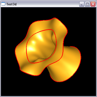
The main algorithm to construct plate surface is GeomPlate_BuildPlateSurface. I use it in CAD Exchanger to translate vertex_blend ACIS surfaces as well as net surfaces. The former is supposed to result from vertex blending and producing a surface G1-continous to neighbours. The image below shows one:
Net surface in ACIS is defined through two sets of curves going in approximately perpendicular directions and forming a grid-like structure. So the resulting surface is supposed to cover that grid as if a roof covered roof-timbers. The image below illustrates this:
As usual, here is an excerpt from the CAD Exchanger code:
/*! The objects in \a theBoundaries must be of the type Adaptor3d_HCurveOnSurface or
GeomAdaptor_HCurve indicating type of a constraint. Otherwise an exception
Standard_TypeMismatch is thrown.
If the \a theBoundaries list is empty then Standard_ConstructionError is thrown.
If the algorithm fails returns a null surface.
*/
Handle(Geom_Surface) ACISAlgo::MakeSurface (const TColStd_ListOfTransient& theBoundaries,
const Standard_Real theTol,
const Standard_Integer theNbPnts,
const Standard_Integer theNbIter,
const Standard_Integer theMaxDeg)
{
//constants for algorithm
const Standard_Integer aNbIter = theNbIter; //number of algorithm iterations
const Standard_Integer aNbPnts = theNbPnts; //sample points per each constraint
const Standard_Integer aDeg = 3; //requested surface degree ?
const Standard_Integer aMaxDeg = theMaxDeg;
const Standard_Integer aMaxSeg = 10000;
const Standard_Real aTol3d = 1.e-04;
const Standard_Real aTol2d = 1.e-05;
const Standard_Real anAngTol = 1.e-02; //angular
const Standard_Real aCurvTol = 1.e-01; //curvature
Handle(Geom_Surface) aRes;
GeomPlate_BuildPlateSurface aPlateBuilder (aDeg, aNbPnts, aNbIter, aTol2d, aTol3d,
anAngTol, aCurvTol);
TColStd_ListIteratorOfListOfTransient anIt (theBoundaries);
if (anIt.More()) {
int i = 1;
for (; anIt.More(); anIt.Next(), i++) {
const Handle(Standard_Transient)& aCur = anIt.Value();
if (aCur.IsNull()) {
assert (0);
Standard_ConstructionError::Raise ("ACISAlgo::MakeSurface()");
} else if (aCur->IsKind (STANDARD_TYPE (Adaptor3d_HCurveOnSurface))) {
//G1 constraint
const Handle(Adaptor3d_HCurveOnSurface)& aHCOS =
Handle(Adaptor3d_HCurveOnSurface)::DownCast (aCur);
Handle (GeomPlate_CurveConstraint) aConst =
new GeomPlate_CurveConstraint (aHCOS, 1 /*GeomAbs_G1*/,
aNbPnts, aTol3d, anAngTol, aCurvTol);
aPlateBuilder.Add (aConst);
} else if (aCur->IsKind (STANDARD_TYPE (GeomAdaptor_HCurve))) {
//G0 constraint
const Handle(GeomAdaptor_HCurve)& aHC =
Handle(GeomAdaptor_HCurve)::DownCast (aCur);
Handle (GeomPlate_CurveConstraint) aConst =
new GeomPlate_CurveConstraint (aHC, 0 /*GeomAbs_G0*/, aNbPnts, aTol3d);
aPlateBuilder.Add (aConst);
} else {
Standard_TypeMismatch::Raise ("ACISAlgo::MakeSurface()");
}
}
} else {
Standard_ConstructionError::Raise ("ACISAlgo::MakeSurface()");
}
//construct
aPlateBuilder.Perform();
if (!aPlateBuilder.IsDone()) {
return aRes;
}
const Handle(GeomPlate_Surface)& aPlate = aPlateBuilder.Surface();
//approximation (see BRepFill_Filling - when no initial surface was given)
Standard_Real aDMax = aPlateBuilder.G0Error();
TColgp_SequenceOfXY aS2d;
TColgp_SequenceOfXYZ aS3d;
aPlateBuilder.Disc2dContour (4, aS2d);
aPlateBuilder.Disc3dContour (4, 0, aS3d);
Standard_Real aMax = Max (aTol3d, 10. * aDMax);
GeomPlate_PlateG0Criterion aCriterion (aS2d, aS3d, aMax);
{
//data races in AdvApp2Var used by GeomApprox_Surface, use global mutex
Standard_Mutex::Sentry aSentry (theBSMutex);
GeomPlate_MakeApprox aMakeApprox (aPlate, aCriterion, aTol3d, aMaxSeg, aMaxDeg);
aRes = aMakeApprox.Surface();
}
return aRes;
}
The code above deals with curve or curve-with-tangency constraints only but you could add point constraints in the same way.
The algorithm starts with creation of initial approximation which you can either specify or it will create a plane otherwise. I have not come across a need of pre-specifying an initial surface but perhaps that would give some hints to the algorithm in complex cases. If there is anyone with such experience, it would be interesting to hear.
To be continued...
P.S. Writing this post in a hotel on the US west coast, Hillsboro, Oregon. The nature here is the greatest I have ever seen. Always enjoying when returning to Oregon...
16 COMMENTS:
Hi Roman,
ReplyWould you be able to say something on the relation between BRepFill_Filling and Geom_Plate? The two seem related but I do not know how exactly. Thanks!
Hi Jelle,
ReplyAs usual there are two levels - geometry and topology. BRepFill_Filling works on the latter and uses Geom_Plate underneath.
I see, though I do not understand why this seemingly duplication?
ReplyAlso the renaming of the concepts ( one would expect BRepFill_Plate, right? ). Anyways. More interesting is the following. The surfacing operation described in your post is called NetworkSrf in Rhino. So, I took a bunch of curves from Rhino, ran GeomPlate_BuildPlateSurface. All seems good, except that Rhino trims the surface that lies outside of the bounding edges.
See the results from PythonOCC and Rhino
Have you noticed that importing a step file in cm units isn't done correctly? OCC assumes it to be mm. This seems to be a common problem with CAD software but it's still a pain in the backside.
ReplyAlso, can you point to the commands to output a brep please? I just can't find it among the masses of files.
Scratch that question, I found it:
ReplyBRepTools::Write(...
(Was heading back home from US, hence delay).
Reply@Jelle:
First, it's not really a duplication. GeomPlate is a common underlying engine which produces the surface (from geometrical constraints).
BRepFill provides additional API which accepts edges (and optionally faces) and creates a *face* bounded by those edges. Compare the following two pictures - Surface andFace, which correspond to the face from the original post. The former results from using GeomPlate, the latter - from BRepOffsetAPI_MakeFilling (internally use BRepFill_Filling). Thus, BRepFill adds extra job by creating a real face not just an underlying surface. In CAD Exchanger, for instance, I only need a surface, as the face boundaries are not its constraints. In some algorithms, working at BRep level can be more convenient to free developer from extra need to reconstruct all face boundaries.
Given this above, the difference from Rhino should not be an issue, right ? GeomPlate algorithm itself is supposed to only satisfy constraint requirements, they do not necessarily become natural surface boundaries. The strong impact, I believe, has the initial approximation surface which can be fed into the algorithm (plane if none is provided). And let's keep in mind that a surface only have 4 natural boundaries. I'm curious what will be Rhino behavior if you specify 5 or more curve constrains which you expect to be boundaries. Can you try that ?
Anyway, boundaries in Open CASCADE come for face, not surface. That's why what you are really interested in eventually, is a face.
As for naming consistency, well, this is not the strongest part of Open CASCADE ;-). Too many components, too many owners, lack of synchronization, etc. It's always a challenge to stay consistent in a large development team (be it Open CASCADE or any other) and it takes extra efforts to preserve it long term.
Hope this helps understand this stuff a bit better ;-)
@jgdes: Can you provide an example of what you believe is an incorrect behavior ?
ReplyI've just imported a step file with cm and then edited it to be mm and imported again. As expected, the shape has 1/10 of length dimension.
I'm happy it doesn't affect you. I'm creating a netgen mesh from a step file and while the step file is in cm the mesh vertices are in mm so i need to rescale. The step file was internally converted to a brep. As far as i can see netgen ignores units completely. Here is the code that gets the step file
Reply/* Special STEP File load function including the ability to extract individual surface colours via the extended OpenCascade XDE and XCAF Feature set. */
OCCGeometry * LoadOCC_STEP (const char * filename)
{
OCCGeometry * occgeo;
occgeo = new OCCGeometry;
// Initiate a dummy XCAF Application to handle the STEP XCAF Document
static Handle_XCAFApp_Application dummy_app = XCAFApp_Application::GetApplication();
// Create an XCAF Document to contain the STEP file itself
Handle_TDocStd_Document step_doc;
// Check if a STEP File is already open under this handle, if so, close it to prevent
// Segmentation Faults when trying to create a new document
if(dummy_app->NbDocuments() > 0)
{
dummy_app->GetDocument(1,step_doc);
dummy_app->Close(step_doc);
}
dummy_app->NewDocument ("STEP-XCAF",step_doc);
STEPCAFControl_Reader reader;
Standard_Integer stat = reader.ReadFile((char*)filename);
// Enable transfer of colours
reader.SetColorMode(Standard_True);
reader.Transfer(step_doc);
// Read in the shape(s) and the colours present in the STEP File
Handle_XCAFDoc_ShapeTool step_shape_contents = XCAFDoc_DocumentTool::ShapeTool(step_doc->Main());
Handle_XCAFDoc_ColorTool step_colour_contents = XCAFDoc_DocumentTool::ColorTool(step_doc->Main());
TDF_LabelSequence step_shapes;
step_shape_contents->GetShapes(step_shapes);
// List out the available colours in the STEP File as Colour Names
TDF_LabelSequence all_colours;
step_colour_contents->GetColors(all_colours);
PrintMessage(4,"Number of colours in STEP File: ",all_colours.Length());
for(int i = 1; i <= all_colours.Length(); i++)
{
Quantity_Color col;
step_colour_contents->GetColor(all_colours.Value(i),col);
PrintMessage(4, "Colour [", i, "] = ",col.StringName(col.Name()));
}
// For the STEP File Reader in OCC, the 1st Shape contains the entire
// compound geometry as one shape
occgeo->shape = step_shape_contents->GetShape(step_shapes.Value(1));
occgeo->face_colours = step_colour_contents;
occgeo->changed = 1;
occgeo->BuildFMap();
// occgeo->BuildVisualizationMesh();
occgeo->CalcBoundingBox();
PrintContents (occgeo);
return occgeo;
}
I'll try that again - 1st time didn't show:
Reply-----
I'm happy it doesn't affect you. I'm creating a netgen mesh from a step file and while the step file is in cm the mesh vertices are in mm so i need to rescale. The step file was internally converted to a brep. As far as i can see netgen ignores units completely. Here is the code that gets the step file
/* Special STEP File load function including the ability to extract individual surface colours via the extended OpenCascade XDE and XCAF Feature set. */
OCCGeometry * LoadOCC_STEP (const char * filename)
{
OCCGeometry * occgeo;
occgeo = new OCCGeometry;
// Initiate a dummy XCAF Application to handle the STEP XCAF Document
static Handle_XCAFApp_Application dummy_app = XCAFApp_Application::GetApplication();
// Create an XCAF Document to contain the STEP file itself
Handle_TDocStd_Document step_doc;
// Check if a STEP File is already open under this handle, if so, close it to prevent
// Segmentation Faults when trying to create a new document
if(dummy_app->NbDocuments() > 0)
{
dummy_app->GetDocument(1,step_doc);
dummy_app->Close(step_doc);
}
dummy_app->NewDocument ("STEP-XCAF",step_doc);
STEPCAFControl_Reader reader;
Standard_Integer stat = reader.ReadFile((char*)filename);
// Enable transfer of colours
reader.SetColorMode(Standard_True);
reader.Transfer(step_doc);
// Read in the shape(s) and the colours present in the STEP File
Handle_XCAFDoc_ShapeTool step_shape_contents = XCAFDoc_DocumentTool::ShapeTool(step_doc->Main());
Handle_XCAFDoc_ColorTool step_colour_contents = XCAFDoc_DocumentTool::ColorTool(step_doc->Main());
TDF_LabelSequence step_shapes;
step_shape_contents->GetShapes(step_shapes);
// List out the available colours in the STEP File as Colour Names
TDF_LabelSequence all_colours;
step_colour_contents->GetColors(all_colours);
PrintMessage(4,"Number of colours in STEP File: ",all_colours.Length());
for(int i = 1; i <= all_colours.Length(); i++)
{
Quantity_Color col;
step_colour_contents->GetColor(all_colours.Value(i),col);
PrintMessage(4, "Colour [", i, "] = ",col.StringName(col.Name()));
}
// For the STEP File Reader in OCC, the 1st Shape contains the entire
// compound geometry as one shape
occgeo->shape = step_shape_contents->GetShape(step_shapes.Value(1));
occgeo->face_colours = step_colour_contents;
occgeo->changed = 1;
occgeo->BuildFMap();
// occgeo->BuildVisualizationMesh();
occgeo->CalcBoundingBox();
PrintContents (occgeo);
return occgeo;
}
Sorry, jgdes, still not get it :-\. Do you mean to say your shape (and hence final mesh, as Netgen has to operate on the OCC TopoDS_Shape model you feed into it, which is units-agnostic) is the same regardless units in the STEP file ? Can you try the same STEP file and manually editing it to replace CM with MM and see if the mesh changes ?
ReplyNo It's just a problem with cm. Inches and mm are ok, but cm become mm. If I changed the STEP file to mm, I'd get a mesh in mm. If i leave it as cm i get mm. If i have inches, i get inches. It's weird! But the same probem happens with several CAD programs apparently, presumably because few people use cm, so it's only a problem because the Alibre STEP output is annoyingly always in cm regardless of what unit you thought you were working in. Is there a command for reporting the units of the OCC model?
ReplyI want to open a STEP file in Visula C++ using opencascade libraries and reconstruct the shapes and do some analysis. I don't know coding much so please tell how to start or provide a sample code.
ReplyRaj, asking someone to do your homework is a little rude. There's plenty of examples that do just what you're after... so get going with the examples that come with OCC. Enjoy.
ReplyRaj,
ReplyJelle is just right - spend your time to learn the product basics and get yourself up to speed. That just works everywhere in life ;-).
Hi
ReplyAbout filling/plating, I posted a case right now here http://www.opencascade.org/org/forum/thread_21490/
I wanted to be G1 on just some of the involved edges/faces. Is it possible?
About "Class A", can we be smoother than G1?
thanks
davide
I'm amazed, I must say. Seldom do I encounter a blog that's
both equally educative and amusing, and without a doubt, you have
hit the nail on the head. The problem is something too few men and women are speaking intelligently about.