2.The-Physics-of-Light-Transport_1
Brief History
Models of Light
The models of light used in simulations try to capture the different behaviors of light that arise from its dual nature: light is a wave and light consists of a stream of particles.
Quantum Optics
This model is generally considered to be too detailed for the purposes of image generation for typical computer graphics scenes and is not
commonly used.
Wave Model
However, for the purposes of image generation in computer graphics, the wave nature of light is also typically ignored.
Geometric Optics
The geometric optics model is the simplest and most commonly used model of light in computer graphics. The geometric optics model assumes that light is emitted, reflected, and transmitted. In this model, several assumptions are made about the behavior of light:
- Light travels in straight lines
- Light travels instantaneously through a medium,this assumption essentially requires light to unrealistically travel at infinite speed
- Light is not influenced by external factors, such as gravity or magnetic fields.
Radiometry
The goal of a global illumination algorithm is to compute the steady-state distribution of light energy in a scene.
To compute this distribution, we need an understanding of the physical quantities that represent light energy. Radiometry is the area of study involved in the physical measurement of light. This section gives a brief overview of the radiometric units used in global illumination algorithms.
Radiometric Quantities
辐射能(Radiant energy)\((Q)\)
电磁辐射(electromagnetic radiation)的能量,单位是焦耳\(J\),用符号表示(很少用在计算机图形学中)
Radiant Power or Flux( $\Phi $ )
This quantity expresses how much total energy flows from/to/through a surface per unit time,expressed in watts(\(W\)) (joules/sec).Note that flux does not specify the size of the light source or the receiver (table), nor does it include a specification of the distance between the light source and the receiver.
单位是\(W\)或者是\(lm\)
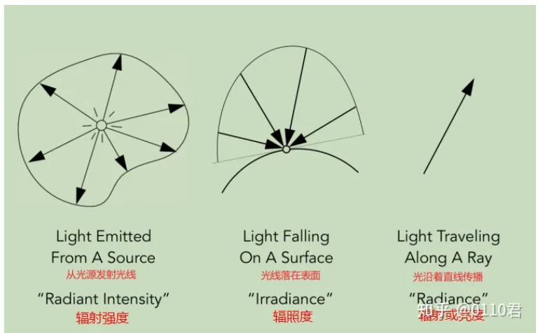
Radiant Intensity\((I)\)
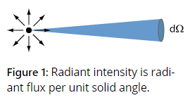
A light source is defined as the emitted radiant flux per unit solid angle.It can also be applied to transmitted, reflected or received radiation.多用于点光源.The corresponding photometric quantity is the luminous intensity in units of candela(cd) = lm/sr.
单位是 \(W/sr\) (watts per steradian).
At a distance \(d\) from a source with radiant intensity \(I\) , an area element with its normal direction at an angle \(\theta\) against the direction to the source receives an irradiance \(E = Icos\theta / d^2\) . The total radiant flux of a source with uniform omnidirectional emission (i.e., and intensity not depending on the direction) is \(\Phi = 4 \pi I\).
Irradiance\((E)\)
Irradiance (E) is the incident(入) radiant power on a surface, per unit surface area. It is expressed in watts/m2
Radiant Exitance(M) or Radiosity(B)
The exitant(出) radiant power per unit surface area and is also expressed in watts/m2:
Radiance or Luminance\((L)\)
Radiance is flux per unit projected area per unit solid angle (watts/(steradian · m2)).Radiance is a five-dimensional quantity that varies with position \(x\) and direction vector \(\Theta\), and is expressed as \(L(x, \Theta)\) (see Figure):
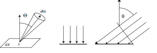
这些这些图片中的符号:\(w\),\(\theta\),此处使用了: unit solid angle \(dw\) ,以及第一和第二个公式的区别.
Transort theory
Transort theory deals with the transport or flow of physical quantities such as energy, charge, and mass. In this section, we use transport theory to formulate radiometric quantities in terms of the flow of “light particles” or “photons.”
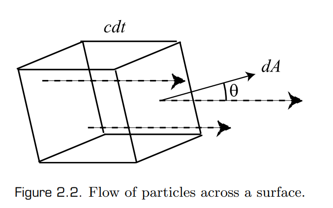
\(p(x)\):is the the density of light particles,defines the number of paritcles per unit volume at some point x.\(dt\):some time;\(dA\) surface area;\(\overrightarrow{c}\) is the velocity of the light particles;The number of particles flowing across the surface is :
\(w\): to denote a direction vecotr
Relationships between Radiometric Quantities
Wavelength Dependency
The radiometric measures and quantities described above are not only dependent on position and direction but are also dependent on the wavelength of light energy. When wavelength is explicitly specified, for example, for radiance, the corresponding radiometric quantity is called spectral radiance.
The units of spectral radiance are the units of radiance divided by meters(the unit of wavelength). Radiance is computed by integrating spectral radiance over the wavelength domain covering visible light.
Properties of Radiance
Property 1: Radiance is invariant along straight paths.
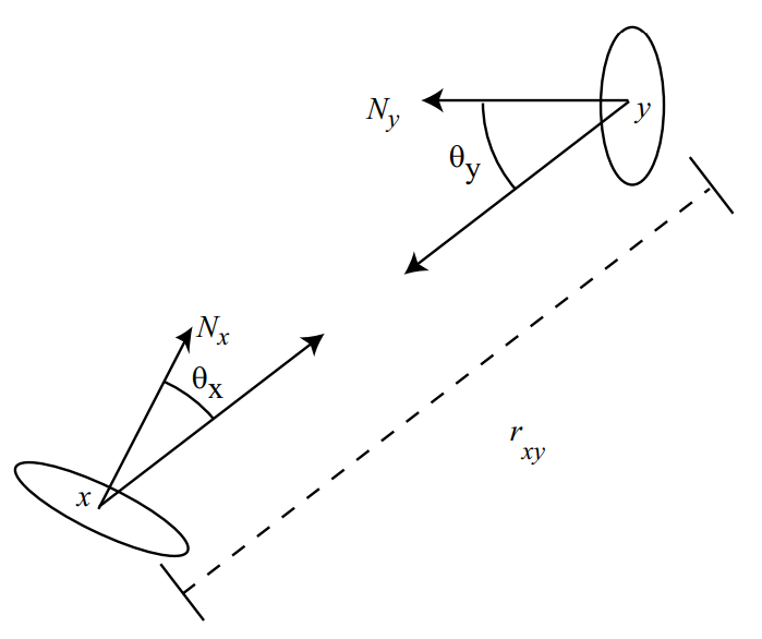
This property assumes that light is traveling through a vacuum(真空) and conservation of light energy in a small pencil of rays between two differential surfaces at x and y.
From the definition of radiance, the total (differential) power leaving a differential surface area \(dAx\), and arriving at a differential surface area \(dAy\), can be written as
where we use the notation that $dw_{x \leftarrow dA_{y}} $is the solid angle subtended by \(dA_{y}\) as seen from x.
The power that arrives at area \(dA_{y}\) from area \(dA_{x}\) can be expressed in a similar way:
The differential solid angles are:
Then, by the law of conservation of energy:
and thus:
From the above observation, it follows that once incident or exitant radiance at all surface points is known, the radiance distribution for all points in a three-dimensional scene is also known.
This property of radiance is only valid in the absence of participating media, which can absorb and scatter energy between the two surfaces.
Property 2: Sensors, such as cameras and the human eye, are sensitive to radiance.
Light Emission
The computation of accurate global illumination requires the specification of the following three distributions for each light source:
spatial,directional, and spectral intensity distribution.
- Idealized spatial distributions of lights assume lights are point lights; morerealistically, lights are modeled as area lights.
- The directional distributions of typical luminaires is determined by the shape of their associated light fixtures.
- Though the spectral distribution of light could also be simulated accurately, global illumination algorithms typically simulate RGB (or a similar triple) for efficiency reasons.
Interaction of Light with Surfaces
BRDF
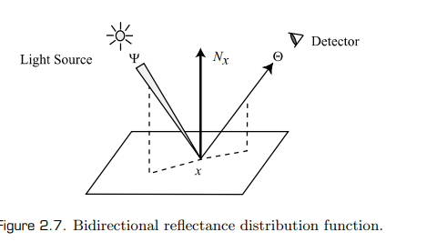
In this book, we assume that light incident at a surface exits at the same wavelength and same time. Therefore, we are ignoring effects such as fluorescence and phosphorescence. In the most general case, light can enter some surface at a point \(p\)
and incident direction $\Psi $ and can leave the surface at some other point \(q\) and exitant direction \(\Theta\). The function defining this relation between the incident and reflected radiance is called the bidirectional surface scattering reflectance distribution function (BSSRDF).
We make the additional assumption that the light incident at some point exits at the same point; thus, we do not discuss subsurface scattering, which results in the light exiting at a different point on the surface of the object.
Given these assumptions, the 🚗 reflectance properties of a surface are
described by a reflectance function called the bidirectional reflectance distribution function (BRDF). The BRDF at a point \(x\) is defined as the ratio of the differential radiance reflected in an exitant direction (\(\Theta\)), and the differential irradiance incident through a differential solid angle (\(dw_{\Psi}\) ). The BRDF is denoted as $ f_{r}(x,\Psi \rightarrow \Theta)$:
where \(cos(N_{x}, \Psi)\) is the cosine of the angle formed by the normal vector at the point \(x\), \(N_{x}\), and the incident direction vector \(\Psi\).
Properties of the BRDF
- Range :The BRDF can take any positive value and can vary with wavelength.
- Dimension: The BRDF is a four-dimensional function defined at each point on a surface; two dimensions correspond to the incoming direction, and two dimensions correspond to the outgoing direction.
- Reciprocity: The value of the BRDF remains unchanged if the incident and exitant directions are interchanged. This property is also called
Helmholtz reciprocity. - Relation between incident and reflected radiance
The value of the BRDF for a specific incident direction is not dependent on the possible presence of irradiance along other incident angles. Therefore, the BRDF behaves as a linear function with respect to all incident directions. The total reflected radiance due to some irradiance distribution over the hemisphere around an opaque, non-emissive surface point can be expressed as:\[dL(x \rightarrow \Theta) = f_{r}(x,\Psi \rightarrow \Theta)dE(x \leftarrow \Psi) \qquad \qquad (2.15) \]\[L(x \rightarrow \Theta) = \int_{ \Omega _{x} } f_{r}(x,\Psi \rightarrow \Theta)dE(x \leftarrow \Psi) \qquad \qquad (2.16) \]\[L(x \rightarrow \Theta) = \int_{ \Omega _{x} } f_{r}(x,\Psi \rightarrow \Theta) cos(N_{x},\Psi)dw_{\Psi} \qquad \qquad (2.17) \] - Energy conservation. The law of conservation of energy requires that the total amount of power reflected over all directions must be less than or equal to the total amount of power incident on the surface.For any distribution of incident radiance L(x ← Ψ) over the hemisphere, the total incident power per unit surface area is the total irradiance over the hemisphere:
The total reflected power M is a double integral over the hemisphere
From the definition of the BRDF, we know $ dL(x \rightarrow \Theta) = f_{r}(x,\Psi \rightarrow \Theta)L(x \leftarrow \Psi)cos(N_{x},\Psi)dw_{\Psi} $.Integrating this equation to find the value for \(L(x \rightarrow \Theta)\) and combining it with the expression for \(M\) gives us
The BRDF satisfies the constraint of energy conservation
BRDF Examples
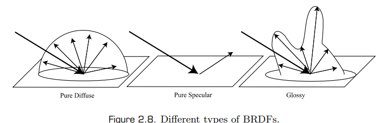
Depending on the nature of the BRDF, the material will appear as a diffuse surface, a mirror, or a glossysurface.
Diffuse Surfaces
Some materials reflect light uniformly over the entire reflecting hemisphere. That is, given an irradiance distribution, the reflected radiance is independent of the exitant direction. Such materials are called diffuse reflectors, and the value of their BRDF is constant for all values of \(\Theta\) and \(\Psi\).
For an ideal diffuse surface,
The reflectance \(\rho _{d}\) represents the fraction of incident energy that is reflected at a surface. For physically-based materials, \(\rho _{d}\) varies from 0 to 1.
Specular Surfaces
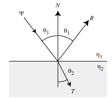
Perfect specular surfaces only reflect or refract light in one specific direction. Specular reflection.
Specular refraction
The direction of specular refraction is computed using Snell’s law. Consider the direction T along which light that is incident from
a medium with refractive index \(\eta _{1}\) to a medium with refractive index \(\eta _{2}\) is refracted:
where \(\theta_{1}\) and \(\theta_{2}\) are the angles between the incident and transmitted ray and the normal to the surface.
refractive index: 介质的 折射率(refractive index) 是光在真空中的相速度与光在介质中的相速度之比值。
- 两种介质的相对折射率是两介质中传播的光速之比;
- 金属的折射率是复数,虚部系数被称为消光系数(extinction coefficient),描述了介质使电磁波衰减的程度;
The transmitted ray T is given as:
When light travels from a dense medium to a rare medium, it could get
refracted back into the dense medium. This process is called total internal reflection; it arises at a critical angle(临界角) \(\theta_{c}\), also known as Brewster’s angle.
Reciprocity for transparent surfaces
When a pencil of light enters a dense medium from a less dense (rare) medium, it gets compressed. This behavior is a direct consequence of Snell’s law of refraction (rays “bend” towards the normal direction). Therefore, the light energy per unit area perpendicular to the pencil direction becomes higher; i.e., the radiance is higher. The reverse process takes place when a pencil of light leaves a dense medium to be refracted into a less dense medium. The change in ray density is the square ratio of the refractive indices of the media [203, 204]: \((\frac{\eta _{2}}{\eta _{1}})^2\). When computing radiance in scenes with transparent surfaces, this weighting factor should be considered.
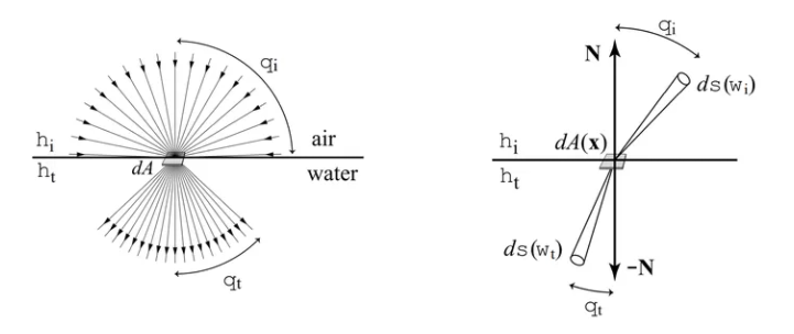
设折射点的面积微元是\(dA\),入射光线的辐射亮度是\(L_{i}\) ,入射光线立体角微元在交界面上的投影是$d\sigma^{\bot}(w_{i}) $,那么入射光线的辐射通量微元 \(d\Phi_{i}\) 如下
同理,折射光线的辐射通量微元\(d\Phi_{t}\) 如下:
当不考虑菲涅尔效应,以及介质本身对光线的系数等因素时,因为能量守恒,即 \(d\Phi_{i}\) = \(d\Phi_{t}\),所以:
另外,光线立体角微元在交界面上的投影 \(d\sigma^{\bot} (w)\) 和天顶角微元\(d\theta\) 以及方位角微元 \(d\phi\) 之间满足
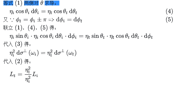
另外,上述关系假设了当光线发生折射时波长没有发生变化,但是实际上入射光线的波长\(\lambda_{i}\)和折射光线的波长\(\lambda_{t}\)存在如下关系:
Specular reflection
The direction of reflection can be found using the law of reflection.
incident dirction: \(\Psi\),normal to the surface is N,be reflected direction is :\(R\)
The BRDF of such a perfect specular reflector can be described with the proper use of δ-functions.
posted on 2024-03-29 14:39 Ultraman_X 阅读(97) 评论(0) 收藏 举报

 浙公网安备 33010602011771号