第一步:搭建开发环境

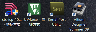
安装最新版本的STC_ISP程序烧录软件,链接:http://pan.baidu.com/s/1slLPnOD 密码:6bov
安装keil C51的51系列单片机集成IDE软件,链接:https://www.keil.com/c51/demo/eval/c51.htm
安装串口程序,链接:http://rj.baidu.com/soft/detail/27520.html?ald
安装Altium Designer,链接:http://www.mr-wu.cn/altium-designer-16-ad16-full-crack-baidu-pan-share/
安装CH340的驱动程序,链接:http://pan.baidu.com/s/1nvG7Mlz 密码:b0ka
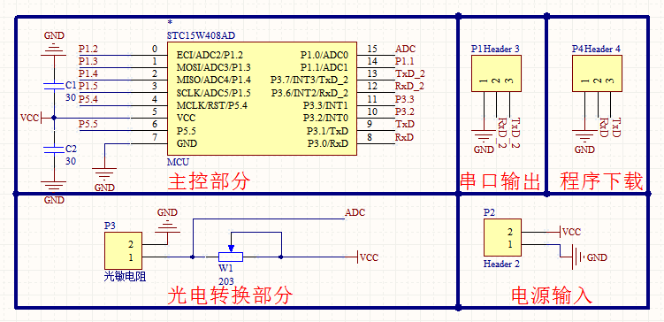
第二步:绘制完整的PCB版图


手工焊好的洞洞板(注意这里的问题:串口的电源不要给芯片供电哟~): 原件清单:


第三部:编写程序
main.c主程序:
 1 #include <STC15W.h>
 2 #include <intrins.h>
 3 #include <BandGap.H>
 4 #include "USART.h"
 5
 6 void main (void)
 7 {
 8     uint ADC_Res=0;
 9     int i = 0;
10     float Voltage = 0.0;
11
12     Delay20ms();
13   InitADC();
14     Usart1_init();
15     P1n_standard(0);
16     SendString("STC15W408AS\r\nFlux Detect!\r\n");
17   while (1)
18   {
19         //P10 = 0;
20         //delay_500ms();
21         for(i=0;i<10;i++)
22         {
23             ADC_Res += GetADCResult(1);
24             Delay20ms();
25         }
26         //P10 = 1;
27         delay_s(30);
28         ADC_Res = ADC_Res/30;
29         Voltage = ((float)ADC_Res)/1024.0*5.0;
30         SendNumber(Voltage);
31         ADC_Res = 0;
32   }
33 }
STC15W头文件上传到了我的博客园文件盘当中:https://files.cnblogs.com/files/uestc-mm/STC15W.rar
ADC模块程序:

  1 #include <STC15W.h>
  2 #include <intrins.h>
  3
  4 #define  uchar unsigned char
  5 #define uint  unsigned int
  6 unsigned int v;
  7 //ADCÏà¹ØÉ趨²ÎÊý
  8 #define ADC_POWER   0x80            //ADCµçÔ´¿ØÖÆλ
  9 #define ADC_FLAG    0x10            //ADCÍê³É±êÖ¾
 10 #define ADC_START   0x08            //ADCÆðʼ¿ØÖÆλ
 11 #define ADC_SPEEDLL 0x00            //540¸öʱÖÓ
 12 #define ADC_SPEEDL  0x20            //360¸öʱÖÓ
 13 #define ADC_SPEEDH  0x40            //180¸öʱÖÓ
 14 #define ADC_SPEEDHH 0x60            //90¸öʱÖÓ
 15
 16 #define ID_ADDR_ROM 0x1ff7      //8K³ÌÐò¿Õ¼äµÄMCU
 17
 18 void Delay20ms()        //@12.000MHz
 19 {
 20     unsigned char i, j, k;
 21
 22     _nop_();
 23     _nop_();
 24     i = 1;
 25     j = 234;
 26     k = 113;
 27     do
 28     {
 29         do
 30         {
 31             while (--k);
 32         } while (--j);
 33     } while (--i);
 34 }
 35
 36 void delay_500ms(void)
 37 {
 38     int i=37;
 39     for(;i>0;i--)
 40     {
 41         Delay20ms();
 42     }
 43 }
 44
 45 void delay_s(char N)
 46 {
 47     char i=0;
 48     for(i=0;i<N;i++)
 49     {
 50         delay_500ms();
 51         delay_500ms();
 52     }
 53 }
 54 /*----------------------------
 55 ³õʼ»¯ADC
 56 ----------------------------*/
 57 void InitADC()
 58 {
 59        P1ASF = 0x02;                   //ÉèÖÃP1¿ÚΪAD¿Ú  P1.1½Ó¿ÚΪADCÊäÈë½Ó¿Ú
 60     ADC_RES = 0;                    //Çå³ý½á¹û¼Ä´æÆ÷
 61     ADC_CONTR = ADC_POWER | ADC_SPEEDLL;
 62     Delay20ms();
 63 }
 64 /*----------------------------
 65 ¶ÁÈ¡ADC½á¹û
 66 ----------------------------*/
 67 uint GetADCResult(uchar ch)
 68 {
 69     uint ADC_10BIT_RES;
 70     ADC_CONTR = ADC_POWER | ADC_SPEEDLL | ch | ADC_START;
 71     _nop_();                        //µÈ´ý4¸öNOP
 72     _nop_();
 73     _nop_();
 74     _nop_();
 75     while (!(ADC_CONTR & ADC_FLAG));//µÈ´ýADCת»»Íê³É
 76     ADC_CONTR &= ~ADC_FLAG;         //¹Ø±Õ ADC
 77     ADC_10BIT_RES=ADC_RES;      //µÃµ½¸ß8λ
 78     ADC_10BIT_RES<<=2;
 79     ADC_10BIT_RES+=ADC_RESL;     //µÃµ½µÍ2λ
 80     return ADC_10BIT_RES;                 //·µ»ØADC½á¹û
 81
 82 }
 83
 84 /*----------------------------
 85 ·¢ËÍADC½á¹û
 86 ----------------------------*/
 87 void ShowResult(uchar ch)
 88 {
 89     uint adc_res10,//²âÁ¿É趨ͨµÀadcÖµ
 90     bandgap,       //bandgapÔ¤´¢´æУ׼ֵ£¬µ¥Î»ºÁ·ü
 91     adc_9gallery_res; //²âÁ¿µÚ¾ÅͨµÀ£¨bandgap£©Öµ
 92     float power_voltage,        //ϵͳ¹©µçµçѹ£¬µ¥Î»ºÁ·ü
 93     ADC_voltage;     //É趨ͨµÀµçѹֵ£¬µ¥Î»ºÁ·ü
 94
 95     uchar  code *cptr; //¶¨ÒåROM(´úÂë)ÇøÖ¸Õë
 96     //uchar  idata *iptr;//¶¨ÒåRAM(ÄÚ´æ)ÇøÖ¸Õë
 97
 98     cptr = ID_ADDR_ROM;         //´Ó³ÌÐòÇø¶ÁÈ¡BandGapµçѹֵ(µ¥Î»:ºÁ·ümV)
 99     bandgap=*cptr++;
100     bandgap<<=8;
101     bandgap+=*cptr;
102     /*iptr = ID_ADDR_RAM;         //´ÓÄÚ´æÇø¶ÁÈ¡BandGapµçѹֵ(µ¥Î»:ºÁ·ümV)
103     bandgap=*iptr++;              //Á½ÖÖ·½·¨½á¹ûÒ»Ñù£¬ÉÏÃæµÄ·½·¨ÐèÒªÔÚÏÂÔØʽ¹´Ñ¡"ÔÚIDºÅÇ°Ìí¼ÓÖØÒª²âÊÔ²ÎÊý"Ñ¡Ïî,²Å¿ÉÔÚ³ÌÐòÖлñÈ¡´Ë²ÎÊý
104     bandgap<<=8;                  //ÏÂÃæµÄ·½·¨²»ÐèÒª
105     bandgap+=*iptr;    */
106     //²âÁ¿É趨ͨµÀadcÖµ
107     ADC_RES = 0;                    //Çå³ý½á¹û¼Ä´æÆ÷
108     P1ASF = 0x80;                   //ÉèÖÃP1¿ÚΪAD¿Ú
109     GetADCResult(ch);
110     GetADCResult(ch);                 //¶ÁÈý´Î»ñµÃÎȶ¨
111     adc_res10= GetADCResult(ch);
112     //²âÁ¿µÚ¾ÅͨµÀ£¨bandgap£©Öµ
113     ADC_RES = 0;                    //Çå³ý½á¹û¼Ä´æÆ÷
114     P1ASF = 0x00;                   //ÉèÖöÁµÚ¾ÅͨµÀ
115     GetADCResult(0);                 //²âbandgapʱ£¬µ÷Óô˺¯ÊýʱͨµÀÊýÖ»ÄÜÌî0
116     GetADCResult(0);                 //¶ÁÈý´Î»ñµÃÎȶ¨
117     adc_9gallery_res=GetADCResult(0);
118     //¼ÆËãϵͳ¹©µçµçѹ
119     power_voltage=(float)bandgap*1024/adc_9gallery_res;
120     //¼ÆËãADCͨµÀ²âµÃµçѹֵ
121     ADC_voltage=(float)bandgap*adc_res10/adc_9gallery_res;
122     v=ADC_voltage;
123     v=v*2;
124 }
USART模块程序:

 1 /*
 2
 3 SBUF: UART1 uses register SBUF (address:99H) to hold both the received and transmitted data passing through pins RxD and TxD.all have two in the chip, one for transmit and the other for receive(OK)
 4
 5 PCON&SCON:Serial port 1 of STC15 series has two control registers: Serial port control register (SCON) and PCONwhich used to select Baud-Rate
 6 SCON:SM0  SM1  Mode  BaudRate
 7             0    1     1  (T1 or T2)/4 (OK)
 8             0    0     0   SYSclk/12
 9 PCON:
10 B7-SMOD
11  0 : Disable double Baud rate of the UART(OK)
12  1 : Enable double Baud rate of the UART in mode 1,2,or 3.
13 B6-SMOD0
14  0 : SCON.7 is SM0 function(OK)
15  1 : SCON.7 is FE function. Note that FE will be set after a frame error regardless of the state of SMOD0.
16
17 AUXR:
18 B6-T1x12:Timer 1 clock source bit
19  0 : The clock source of Timer 1 is SYSclk/12. It will compatible to the traditional 8051 MCU
20  1 : The clock source of Timer 1 is SYSclk/1. It will drive the T0 faster than a traditional 8051 MCUIf T1 is used as the baud-rate generator of UART1, T1x12 will decide whether UART1 is 1T or 12T.(OK)
21 B0 - S1ST2 : the control bit that UART1 select Timer 2 as its baud-rate generator.
22  0 : Select Timer 1 as the baud-rate generator of UART1(OK)
23  1 : Select Timer 2 as the baud-rate generator of UART1. Timer 1 is released to use in other functions
24
25 IE:
26 B7-EA : disables all interrupts.
27  0 : no interrupt will be acknowledged.
28  1 : each interrupt source is individually enabled or disabled by setting or clearing its enable bit.(OK)
29 B4-ES : Serial port 1(UART1) interrupt enable bit.
30  0 : Serial port 1(UART1) interrupt would be diabled.
31  1 : Serial port 1(UART1) interrupt would be enabled.(OK)
32
33 Timer1 Configuration£º
34  #define    Timer1_Load(n)    TH1 = (n)/256,TL1 = (n)%256 Use this sentence to set the T1.So we need to calculate the buad_rate we need£¡
35
36
37 ×ÛºÏÉÏÊöµÄ¼Ä´æÆ÷µÄÅäÖã¬ÎÒÃǽ«Ñ¡ÔñTimer1À´²úÉúUSART1µÄ²¨ÌØÂʵÄʱÖÓÔ´£¬ÎÒÃÇÑ¡ÔñµÄSerial PortµÄģʽMode=1,µ±Êý¾Ý´«ÊäÍê³Éʱ»á²úÉúÖжϣ¬
38 ÎÒÃÇ¿ÉÒÔͨ¹ý¼ì²éÖжÏÏòÁ¿TI(SCON-B1)µÄÖµÀ´ÅжÏÊý¾ÝµÄ´«ÊäÊÇ·ñÍê³É£¬Íê³ÉÔòΪ1£¬Î´Íê³ÉÔòΪ0£ºwhile(TI == 0); --> TI = 0;(²»ÒªÍü¼ÇÇåÁã)
39
40 ÄÇô²¨ÌØÂʵļÆËãÈçÏ£ºBuad_Rate = T1/4
41 É趨µÄTimer1ʱÖÓÈçÏ£ºTime_Clk = SYSclk/1
42 */
43 #include <STC15W.h>
44 #include <intrins.h>
45
46 typedef unsigned char BYTE;
47 typedef unsigned int WORD;
48
49 #define FOSC 18432000L //System frequency  18.432MHz
50 #define BAUD 115200 //UART1 baud-rate
51
52 void Usart1_init(void);
53 void SendData(BYTE dat);
54 void SendString(char *s);
55
56 void Usart1_init(void)
57 {
58     SCON  = (SCON & 0x3f) | 0x40; //Ñ¡Ôñusart1µÄmodeΪ1
59     S1_USE_P30P31();
60     Timer2_1T(); //The clock source of Timer 2 is SYSclk/1.
61     Timer2_AsTimer(); // TMOD &= ~(1<<6) ¶¨Ê±Æ÷1ÓÃ×ö¶¨Ê±Æ÷
62     S1_BRT_UseTimer2(); //Select Timer 1 as the baud-rate generator
63     T2L = (65536 - (FOSC/4/BAUD)); //Set the preload value
64     T2H = (65536 - (FOSC/4/BAUD))>>8;
65     EA = 1;
66     ES = 1;
67     Timer2_Run(); // Æô¶¯¶¨Ê±Æ÷1
68 }
69
70 void SendData(BYTE dat)
71 {
72     SBUF = dat;
73     while(!TI);
74     TI = 0;
75 }
76
77 void SendString(char *s)
78 {
79  while (*s)
80  {
81      SendData(*s++);
82  }
83 }
84
85 void SendNumber(float num)
86 {
87     int a,b;
88     a = (int)num;
89     b = (int)((num-a)*10);
90     SendData((unsigned char)(a+48));
91     SendData('.');
92     SendData((unsigned char)(b+48));
93     SendData('\n');
94 }
第五步:下载程序
 我用的是CP2102的驱动芯片
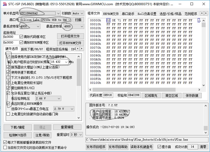
这里是我的选择的设置

注:在这过程中遇到的问题罗列如下
1 下载程序出现BUG:
STC-ISP提示“调整频率无响应”,下载失败的字样,按照官网的步骤意义排查,还是没能解决问题,最后看到宏晶官网的重要提示(参考网站:http://www.stcisp.com/q_and_a_stcisp.html):
一、(特别注意:烧写点击编程键后,单片机必须断电进行冷启动!)
二、部分USB转串口线会通过RxD/TxD引脚对单片机供电,导致下载时不能彻底断电。可在单片机的TxD引脚串一个二极管(接正极,如图),使单片机可彻底断电冷启动。(注:若USB转串口芯片共板,不要对USB芯片断电,否则USB转换的串口会消失)
三、供电部分最好不要用串口的VCC和GND来连接,直接用单独的电源就好。
2 Keil C51的集成IDE中未能找到STC15W408AS的解决办法(参考网站:http://www.stcmicro.com/wtjd.html):
*STC 单片机应使用何种编译器/汇编器?
1任何老的编译器/汇编器都可以支持,流行用Keil C51
2.把STC单片机,当成Intel的8052/87C52/87C54/87C58,Philips的P87C52/P87C54/P87C58就可以了
3.如果要用到扩展的专用特殊功能寄存器,直接对该地址单元设置就行了,当然先声明特殊功能寄存器的地址较好
*Keil C51编译器中无STC单片机型号,怎么办?
1.把STC单片机,当成Intel的8052/87C52/87C54/87C58,Philips的P87C52/P87C54/P87C58就可以了
2.也可安装STC仿真器的驱动程序,这样就看到型号了.
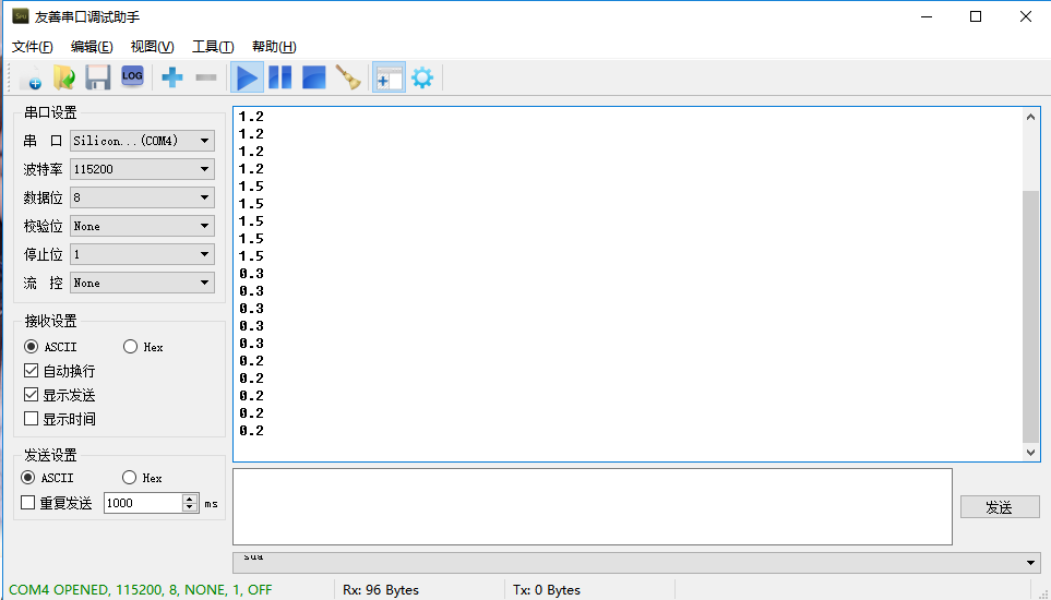
实验结果:


