SystemVerilog -- 6.5 Interface ~ Clocking Block Part II
SystemVerilog Clocking Block Part II
时钟模块允许在指定的时钟事件对输入进行采样并驱动输出。如果提到时钟模块的输入skew,则该模块中的所有输入信号都将在时钟事件之前以skew时间单位进行采样。如果提到时钟模块的输出skew,则该模块中的输出信号都将在相应的时钟事件之后以skew时间单位驱动。
What are input and output skews ?
skew被指定为常量表达式或参数。如果仅使用一个数字,则skew被解释为遵循给定范围内的活动时间刻度。
clocking cb @(clk);
  input  #1ps req;
  output #2   gnt;
  input  #1 output #3 sig;
endclocking
在上面给出的示例中,我们声明了一个名为cb的时钟块,以描述何时必须对属于该块的信号进行采样。信号req被指定为具有1ps的偏移,并将在时钟边沿clk之前采样1ps。输出信号gnt的输出偏差为2个时间单位,因此将遵循当前示波器中遵循的时间刻度。如果我们的时间刻度为1ns/1ps,则#2表示2ns,因此将在时钟边沿后2ns驱动。最后一个信号sig是type的,将在时钟边沿之前1ns采样,在时钟边沿后3ns驱动。inout
输入skew表示信号应在前一个时间步长的末尾采样,或者换言之,应在positive clock edge之前采样。1step
clocking cb @(posedge clk);
  input #1step req;
endclocking
具有显示#0 skew 的输入将与其相应的时钟事件同时采样,但在 Observed 区域中以避免竞争条件。同样,在Re-NBA区域中,没有skew或显示#0的输出将与计时事件同时驱动。
Example
考虑一个简单的设计,输入clk和req,并驱动输出信号gnt。为了简单起见,让我们在收到请求后立刻提供赠款。
module des (input req, clk, output reg gnt);
  always @(posedge clk) begin
    if (req)
      gnt <= 1;
    else
      gnt <= 0;
  end
endmodule
为了处理设计端口信号,让我们创建一个名为_if的简单接口。
interface _if (input bit clk);
  logic gnt;
  logic req;

  clocking cb @(posedge clk);
    input  #1ns gnt;
    output #5   req;
  endclocking
endinterface
下一步是驱动设计的输入,使其返回授予信号。
module tb;
bit clk;

// Create a clock and initialize input signal
always #10 clk = ~clk;
initial begin
  clk <= 0;
  if0.cb.req <= 0;
end

// Instantiate the interface
_if if0 (.clk(clk));

// Instantiate the design
des d0 (
        .clk(clk),
        .req(if0.req),
        .gnt(if0.gnt)
       );

// Drive stimulus
initial begin
  for (int i = 0; i < 10; i++) begin
    bit[3:0] delay = $random;
    repeat (delay) @(posedge if0.clk);
    if0.cb.req <= ~ if0.cb.req;
  end
  #20 $finiash;
end
endmodule
从仿真输出窗口可以看出,req是在时钟边沿之后#5ns驱动的。

Output skew
为了清楚地了解输出偏移,让我们调整界面,使其具有三个不同的时钟块,每个时钟块具有不同的输出偏移。然后,让我们用每个时钟块驱动req以查看差异。
interface _if (input bit clk);
  logic gnt;
  logic req;

  clocking cb_0 @(posedge clk);
    output #0 req;
  endclocking

  clocking cb_1 @(posedge clk);
    output #2 req;
  endclocking

  clocking cb_2 @(posedge clk);
    output #5 req;
  endclocking

endinterface
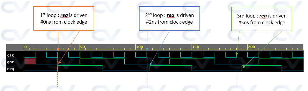
在我们的testbench中,我们将使用循环来迭代每个激励,并为每次迭代使用不同的时钟块。for
module tb;
  // ... part of code same as before

  // Drive stimulus
  initial begin
    for (int i = 0; i < 3; i++) begin
      repeat (2) @(if0.cb_0);
      case (i)
        0 : if0.cb_0.req <= 1;
        1 : if0.cb_1.req <= 1;
        2 : if0.cb_2.req <= 1;
      endcase
      repeat (2) @(if0.cb_0);
      if0.req <= 0;
    end
    #20 $finish;
  end
endmodule
Input skew
为了理解输入偏差,我们将更改 DUT 以仅 #1ns 提供一个随机值,仅用于我们的目的。
module des (output reg[3:0] gnt);
  always #1 gnt <= $random;
endmodule
接口模块将具有不同的时钟模块声明,就像之前一样,每个声明具有不同的输入偏差。
interface _if (input bit clk);
  logic [3:0] gnt;

  clocking cb_0 @(posedge clk);
    input #0 gnt;
  endclocking

  clocking cb_1 @(posedge clk);
    input #1step gnt;
  endclocking

  clocking cb_2 @(posedge clk);
    input #1 gnt;
  endclocking

  clocking cb_3 @(posedge clk);
    input #2 gnt;
  endclocking

endinterface
在testbench中,我们将在时间0ns分叉4个不同的线程,其中每个线程等待适中的正边沿并采样 DUT 的输出。
module tb;
  bit clk;

  always #5 clk = ~clk;

  _if if0 (.clk(clk));
  des d0 (.gnt(if0.gnt));

  initial begin
    fork
      begin
        @(if0.cb_0);
        $display("cb_0.gnt = 0x%0h", if0.cb_0.gnt);
      end
      begin
        @(if0.cb_1);
        $display("cb_1.gnt = 0x%0h", if0.cb_1.gnt);
      end
      begin
        @(if0.cb_2);
        $display("cb_2.gnt = 0x%0h", if0.cb_2.gnt);
      end
      begin
        @(if0.cb_3);
        $display("cb_3.gnt = 0x%0h", if0.cb_3.gnt);
      end
    join
    #10 $finish;
  end
endmodule
输出波形如下图所示,可以看出该设计每#1ns驱动一个随机值。
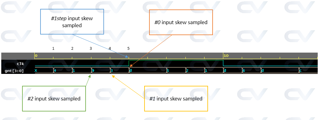
需要注意的是,通过时钟块采样cb_1testbench代码设法获得了0x3值,而cb_0得到了0xd。请注意,对于其他模拟器,这些值可能不同,因为它们可以采用不同的随机化种子值。
模拟日志
ncsim> run
cb_3.gnt = 0x9
cb_2.gnt = 0x3
cb_1.gnt = 0x3
cb_0.gnt = 0xd
Simulation complete via $finish(1) at time 15 NS + 0