计算机组成原理
门电路实现#
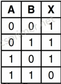
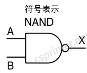
与非门
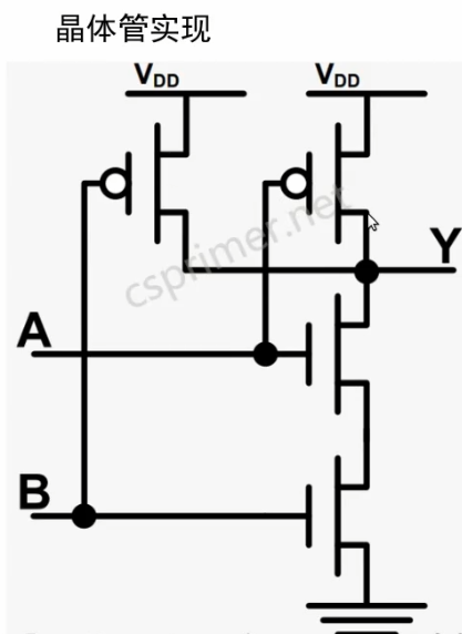
可以使用两个NMOS管串联跟两个PMOS管并联构成:
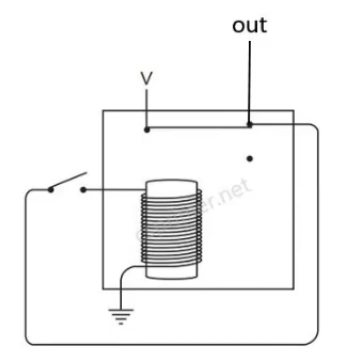
NMOS管是当gate输入高电压导通,PMOS管是当gate输入低电压的时候导通。
等价电路:交换律、结合律、分配律、德摩根律、幂等律、双重否定律
与非门Verilog HDL表示
module Nand(input a, b, output out);
  nmos n1(o1, 0, b);
  nmos n2(out, o1, a);

  pmos p1(out, 1, b);
  pmos p2(out, 1, a);
endmodule
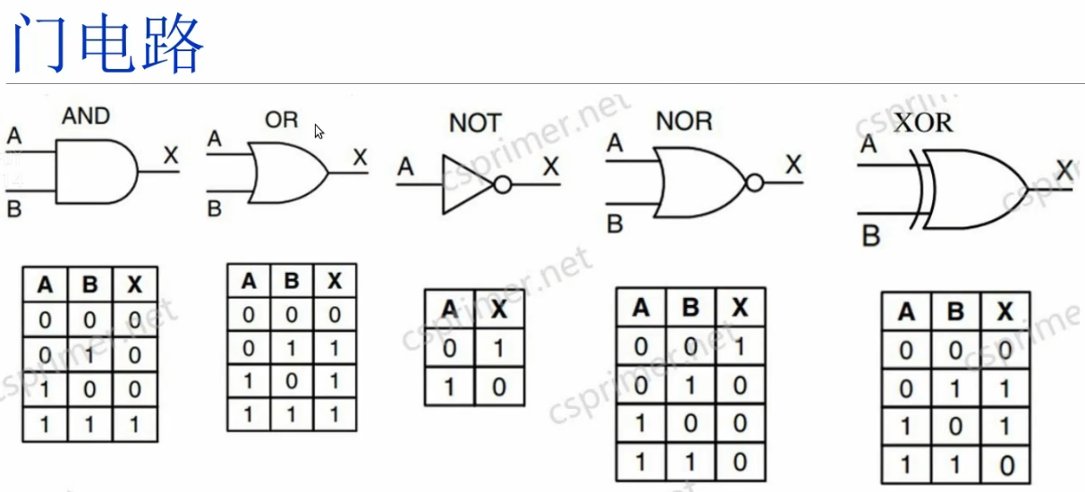
与门实现(用两个与非门连接)
module And(input a, b, output out);
  Nand g1(a, b, AnandB);
  Nand g2(AnandB, AnandB, out);
endmodule
非门实现(两个输入一样的与非门)
module Not(input in, output out);
  // your code here
  Nand  g1(in,in,out);
endmodule
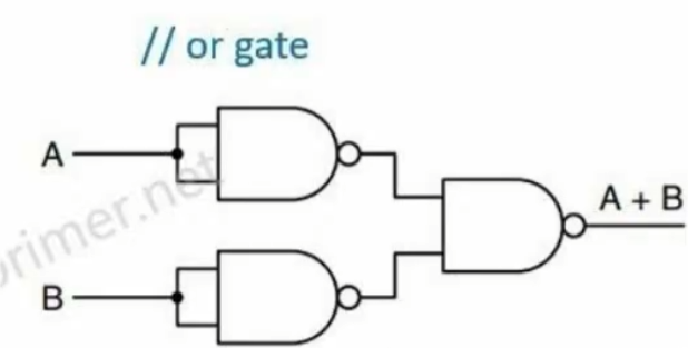
或门实现(三个与非门)
module Or(input a, b, output out);
  // your code here
  wire nand_a, nand_b;

    // 第一个NAND门,模拟 NAND(A, A)
    Nand nand1(a, a, nand_a);

    // 第二个NAND门,模拟 NAND(B, B)
    Nand nand2(b, b, nand_b);

    // 最后一个NAND门,模拟 NAND(nand_a, nand_b),得到 OR 结果
    Nand nand3(nand_a, nand_b, out);
endmodule
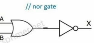
或非门(一个或门和一个非门)
module Nor(input a, b, output out);
  // your code here
       wire out1;
	Or g1(a,b,out1);
	Nand g2(out1,out1,out);
endmodule
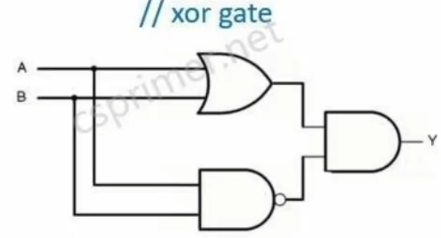
异或门(一个或门和一个与非门并联,再接一个与门)
module Xor(input a, b, output out);
  // your code here
wire out1,out2;
  Or g1(a,b,out1);
  Nand g2(a,b,out2);
  And g3(out1,out2,out);
endmodule
加法器实现#
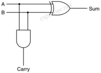
先看半加器
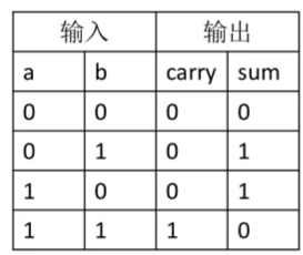
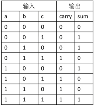
通过一位的加法的真值表:
sum符合异或门特性,carry符合与门特性,得到:
module HalfAdder(input a,b, output sum, carry);
  // your code here
  Xor g1(a,b,sum);
  And g2(a,b,carry);
endmodule
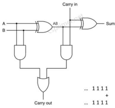
全加器(考虑进位)
module FullAdder(input a,b,c, output sum, carry);
  // your code here
 wire AB,carry1,carry2;
  HalfAdder g1(a,b,AB,carry1);
  HalfAdder g2(AB,c,sum,carry2);
  Or g3(carry1,carry2,carry);
endmodule
16位加法器
module Add16(input[15:0] a,b, output[15:0] out);
  // your code here
 wire [15:0] c;
  FullAdder g01(a[0],b[0],1'b0,out[0],c[0]);
  FullAdder g02(a[1],b[1],c[0],out[1],c[1]);
  FullAdder g03(a[2],b[2],c[1],out[2],c[2]);
  FullAdder g04(a[3],b[3],c[2],out[3],c[3]);
  FullAdder g05(a[4],b[4],c[3],out[4],c[4]);
  FullAdder g06(a[5],b[5],c[4],out[5],c[5]);
  FullAdder g07(a[6],b[6],c[5],out[6],c[6]);
  FullAdder g08(a[7],b[7],c[6],out[7],c[7]);
  FullAdder g09(a[8],b[8],c[7],out[8],c[8]);
  FullAdder g10(a[9],b[9],c[8],out[9],c[9]);
  FullAdder g11(a[10],b[10],c[9],out[10],c[10]);
  FullAdder g12(a[11],b[11],c[10],out[11],c[11]);
  FullAdder g13(a[12],b[12],c[11],out[12],c[12]);
  FullAdder g14(a[13],b[13],c[12],out[13],c[13]);
  FullAdder g15(a[14],b[14],c[13],out[14],c[14]);
  FullAdder g16(a[15],b[15],c[14],out[15],c[15]);
endmodule
减法
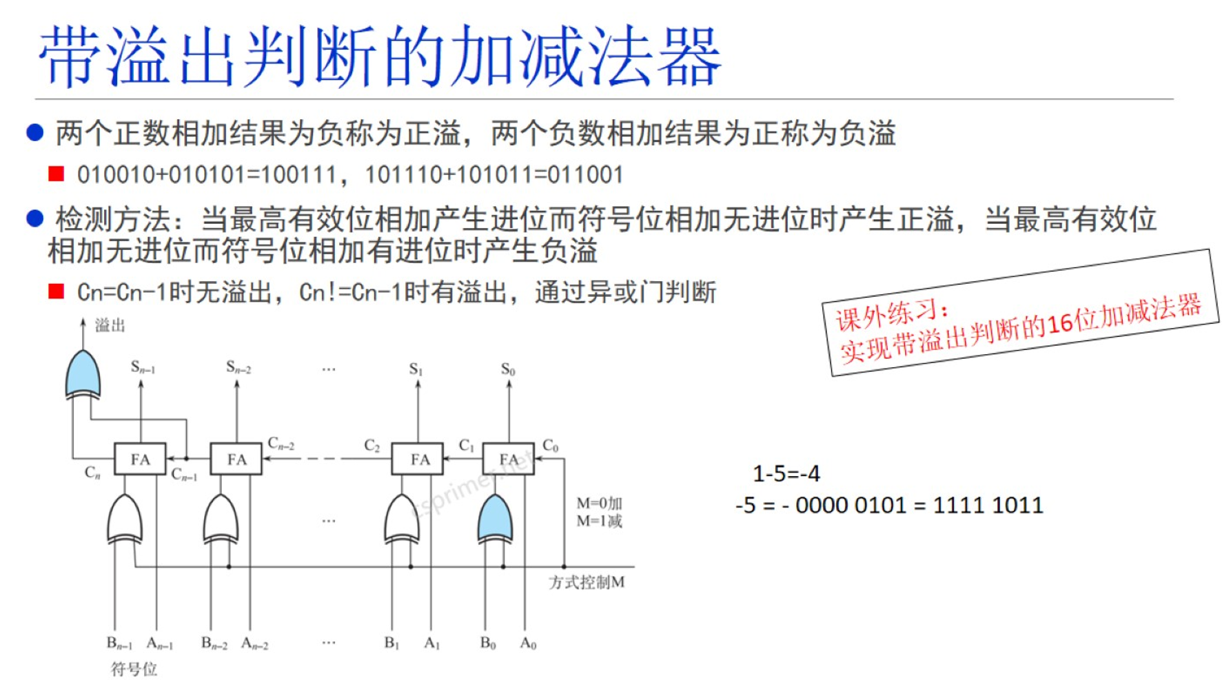
负数的补码由他的正数按位取反再加1
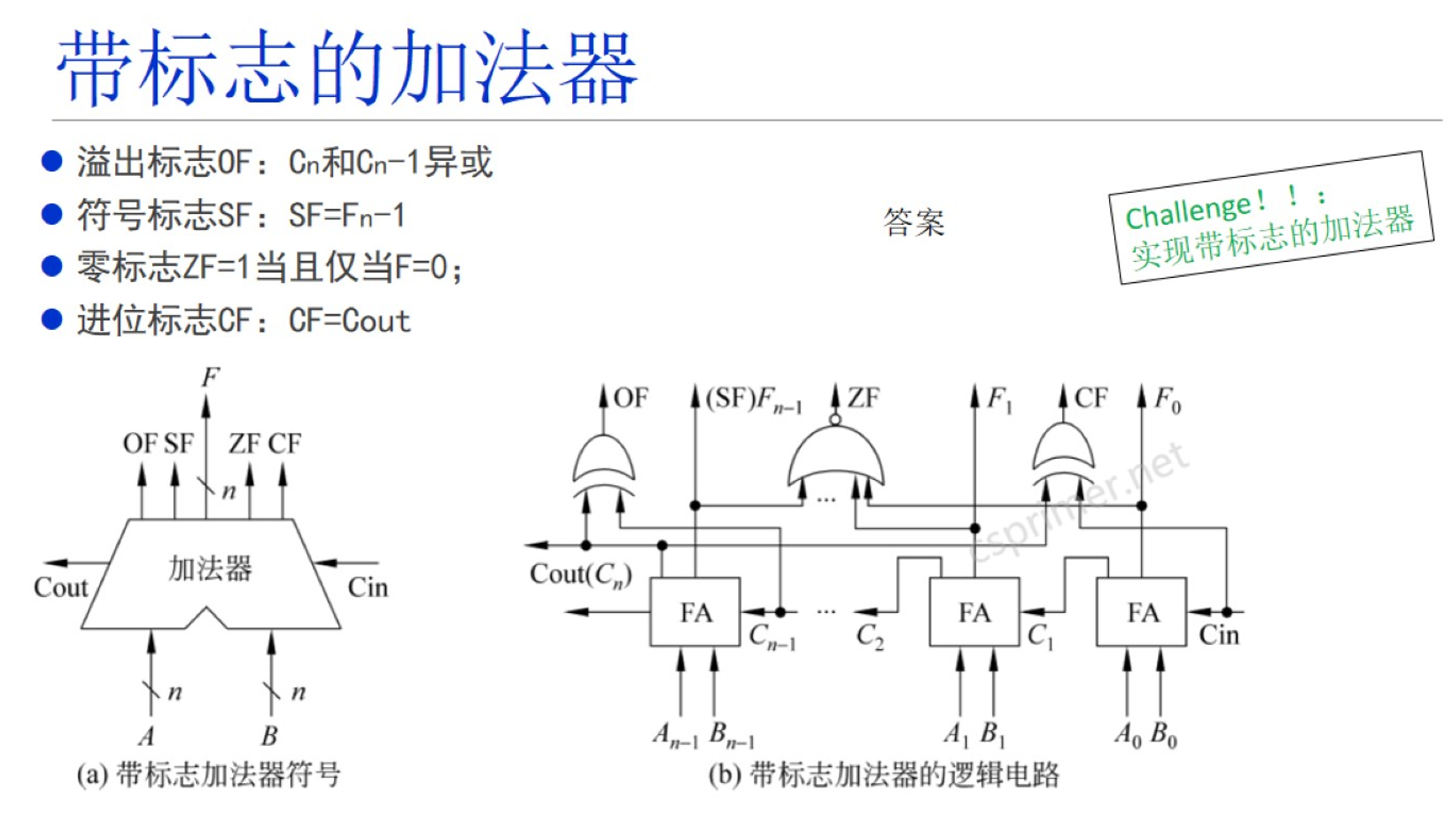
带溢出判断的加法器
两正数相加结果为负数=正溢
两负数相加结果为正=负溢
寄存器存储器的实现#
时钟
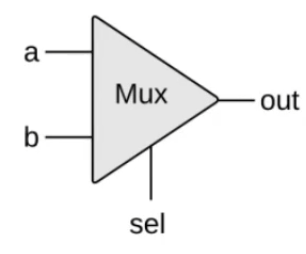
多路选择器(multiplexor)
sel = 0,选择a作为输出
sel =1,选择b作为输出
/**
 * Multiplexor:
 * if (sel == 0) out = a
 *   else out = b
 */

module Mux(input a, b, sel, output out);
  Not g1(sel, nsel);
  And g2(a, nsel, o1);
  And g3(b, sel, o2);
  Or  g4(o1, o2, out);
endmodule
16位的多路选择器
/**
 * 16-bit multiplexor:
 * for i = 0..15 out[i] = a[i] if sel == 0
 *                        b[i] if sel == 1
 */

module Mux16(input[15:0] a, b, input sel, output[15:0] out);
  Mux g15(a[15], b[15], sel, out[15]);
  Mux g14(a[14], b[14], sel, out[14]);
  Mux g13(a[13], b[13], sel, out[13]);
  Mux g12(a[12], b[12], sel, out[12]);
  Mux g11(a[11], b[11], sel, out[11]);
  Mux g10(a[10], b[10], sel, out[10]);
  Mux g09(a[9],  b[9],  sel, out[9]);
  Mux g08(a[8],  b[8],  sel, out[8]);
  Mux g07(a[7],  b[7],  sel, out[7]);
  Mux g06(a[6],  b[6],  sel, out[6]);
  Mux g05(a[5],  b[5],  sel, out[5]);
  Mux g04(a[4],  b[4],  sel, out[4]);
  Mux g03(a[3],  b[3],  sel, out[3]);
  Mux g02(a[2],  b[2],  sel, out[2]);
  Mux g01(a[1],  b[1],  sel, out[1]);
  Mux g00(a[0],  b[0],  sel, out[0]);
endmodule
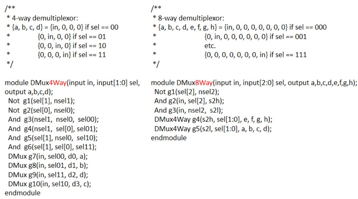
4way/8way 多路选择器
即输入4个情况/输入8个情况
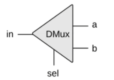
多路复用器(Demultiplexor)
/**
 * Demultiplexor:
 * if sel == 0, a= in, b = 0;
 * if sel == 1, a= 0, b = in;
 */

module DMux(input in, sel, output a, b);
  Not g1(sel, nsel);
  And g2(nsel, in, a);
  And g3(sel,  in, b);
endmodule
4way/8way 多路复用器
即输出4个情况/输出8个情况
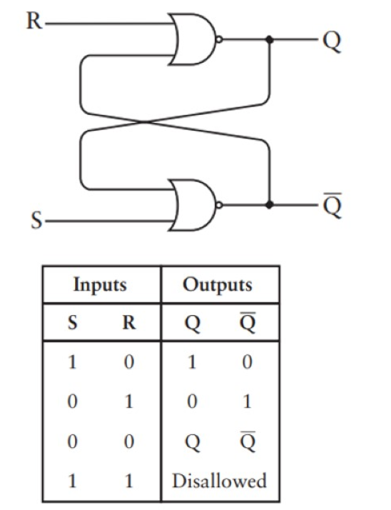
SR锁存器
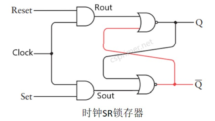
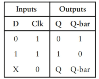
时钟SR锁存器(当时钟=1时候,输出才受r 和s 影响,当时钟=0,输出保持之前的值)
module SRFF (input R, clock, S, output Q, Q_dot);
  // your code here
  wire Rout,Sout;
   And g1(R,clock,Rout);
  And g2(S,clock,Sout);
  Nor g3(Rout,Q_dot,Q);
  Nor g4(Sout,Q,Q_dot);
endmodule
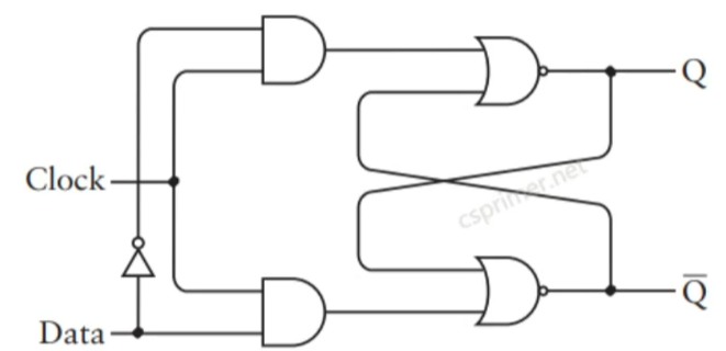
D锁存器(就是把SR锁存器两个输入变成一个输入)也叫电平触发
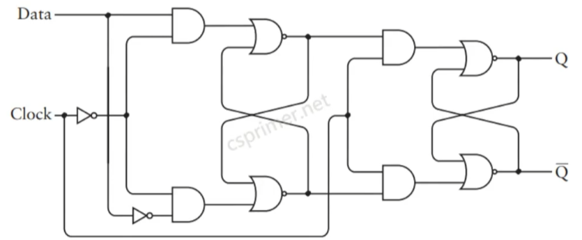
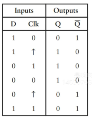
D触发器(两个时钟SR锁存器构成),属于边沿触发,只有当时钟从0->1时才是输出等于输入,其他情况保持之前的值。
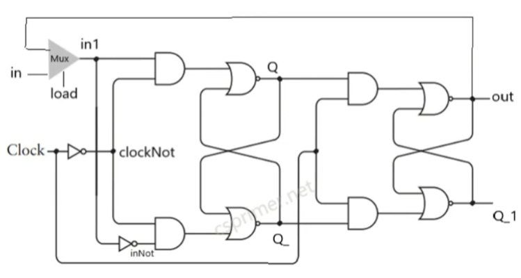
D触发器的实现
module DFF(input in, clock, load, output out);
  // your code here
  wire in1,inNot,clockNot,Q,Q_,Q_dot;
  Mux g1(out,in,load,in1);
  Not g3(in1,inNot);
  Not g4(clock,clockNot);
  SRFF g2(in1,clockNot,inNot,Q, Q_);
  SRFF g5(Q,clock,Q_,out, Q_dot);

endmodule
16位的寄存器(16个D触发器),当load=1,时钟从0->1的时候,输出等于输入。当load=0,就保持之前的值。
/**
 * 16-bit register:
 * If clk[t] == 1 then out[t+1] = in[t]
 * else out does not change
 */

module Register(input[15:0] in, input clock, load, output[15:0] out);
  DFF g01(in[15], clock, load, out[15]);
  DFF g02(in[14], clock, load, out[14]);
  DFF g03(in[13], clock, load, out[13]);
  DFF g04(in[12], clock, load, out[12]);
  DFF g05(in[11], clock, load, out[11]);
  DFF g06(in[10], clock, load, out[10]);
  DFF g07(in[9],  clock, load, out[9]);
  DFF g08(in[8],  clock, load, out[8]);
  DFF g09(in[7],  clock, load, out[7]);
  DFF g10(in[6],  clock, load, out[6]);
  DFF g11(in[5],  clock, load, out[5]);
  DFF g12(in[4],  clock, load, out[4]);
  DFF g13(in[3],  clock, load, out[3]);
  DFF g14(in[2],  clock, load, out[2]);
  DFF g15(in[1],  clock, load, out[1]);
  DFF g16(in[0],  clock, load, out[0]);
endmodule
8个寄存器组合成一个RAM8的存储器,input[2:0] address有3位也就是八个地址,分别对应八个寄存器
通过多路复用器,当load=1时,选择把输入存储到哪个寄存器里,比如load=1,address=1,就把loadB设为1,当时钟0->1时候,o1=in(输出等于输入)
然后再使用多路选择器,通过地址选择哪个寄存器作为输出。
module RAM8(input[15:0] in, input clk, load, input[2:0] address, output[15:0] out);
  wire[15:0] o0,o1,o2,o3,o4,o5,o6,o7;

  DMux8Way g0(load, address, loadA, loadB, loadC, loadD, loadE, loadF, loadG, loadH);

  Register r0(in, clk, loadA, o0);
  Register r1(in, clk, loadB, o1);
  Register r2(in, clk, loadC, o2);
  Register r3(in, clk, loadD, o3);
  Register r4(in, clk, loadE, o4);
  Register r5(in, clk, loadF, o5);
  Register r6(in, clk, loadG, o6);
  Register r7(in, clk, loadH, o7);

  Mux8Way16 g1(o0, o1, o2, o3, o4, o5, o6, o7, address, out);
endmodule
8个RAM8存储器组合成RAM64,地址范围0-5,即2的6次方64个地址
address[5:3] 前三位八个地址,作为8个RAM8的选择
address[2:0] 后三位8个地址,作为8个寄存器的选择
module RAM64(input [15:0] in, input clk,load, input [5:0] address, output [15:0] out);
    wire[15:0] o1, o2, o3, o4, o5, o6, o7, o8;
    DMux8Way d1(load, address[5:3], loadA, loadB, loadC, loadD, loadE, loadF, loadG, loadH);

    RAM8 r1(in, clk, loadA, address[2:0], o1);
    RAM8 r2(in, clk, loadB, address[2:0], o2);
    RAM8 r3(in, clk, loadC, address[2:0], o3);
    RAM8 r4(in, clk, loadD, address[2:0], o4);
    RAM8 r5(in, clk, loadE, address[2:0], o5);
    RAM8 r6(in, clk, loadF, address[2:0], o6);
    RAM8 r7(in, clk, loadG, address[2:0], o7);
    RAM8 r8(in, clk, loadH, address[2:0], o8);

    Mux8Way16 m1(o1, o2, o3, o4, o5, o6, o7, o8, address[5:3], out);
endmodule
8个RAM64存储器组合成RAM512,地址范围0-8,即2的9次方512个地址
module RAM512(input [15:0] in, input clk,load, input [8:0] address, output [15:0] out);
    // your code here
    wire[15:0] o1, o2, o3, o4, o5, o6, o7, o8;
    DMux8Way d1(load, address[8:6], loadA, loadB, loadC, loadD, loadE, loadF, loadG, loadH);

    RAM64 r1(in, clk, loadA, address[5:0], o1);
    RAM64 r2(in, clk, loadB, address[5:0], o2);
    RAM64 r3(in, clk, loadC, address[5:0], o3);
    RAM64 r4(in, clk, loadD, address[5:0], o4);
    RAM64 r5(in, clk, loadE, address[5:0], o5);
    RAM64 r6(in, clk, loadF, address[5:0], o6);
    RAM64 r7(in, clk, loadG, address[5:0], o7);
    RAM64 r8(in, clk, loadH, address[5:0], o8);
    Mux8Way16 m1(o1, o2, o3, o4, o5, o6, o7, o8, address[8:6], out);

endmodule
执行会很慢。需要verilog高级语法。
16位CPU指令设计#
指令设计
D寄存器:仅用来存储数据值
A寄存器:存储地址或数据
A指令:用来为A寄存器设置15位的值
C指令:完成算术逻辑操作,存储器读写操作,控制流跳转操作
介绍C指令的comp域,a=0,按照左边计算。a=1,按照右边计算。
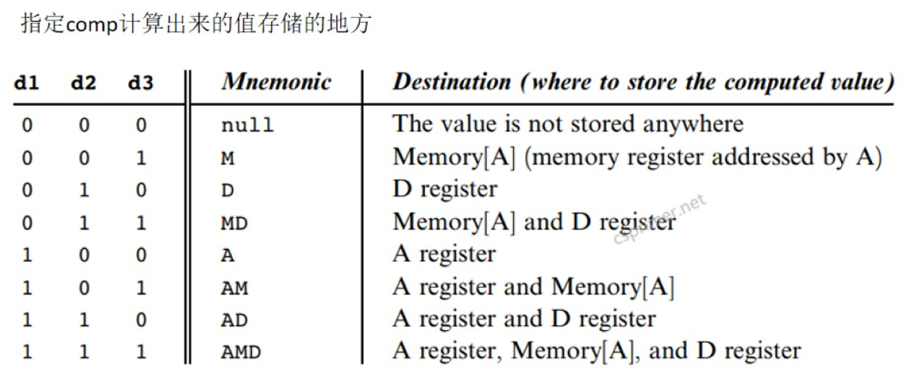
介绍C指令的dest域,他是用来指定comp计算出来的值存储的地方。
d1对应A寄存器,1,0,0表示把结果存储在A寄存器
d2对应D寄存器,0,1,0表示把结果存储在D寄存器
d3对应Memory[A],0,0,1表示把结果存住在Memory[A]
三个都为0表示不存储值。三个都为1表示这三个地方都存储。
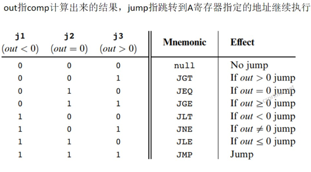
介绍C指令的jump域
0 0 0 不跳转
1 1 1无条件跳转
其他情况,根据comp计算出来的结果判断,如:0 1 0,out=0,跳转
ALU实现#
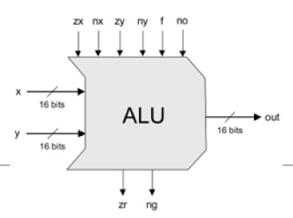
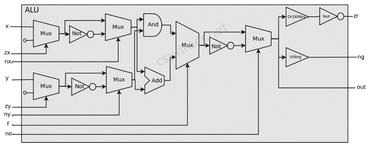
ALU主要实现C指令comp域描述的计算,他有两个16位的输入系x,y,一个16位的输出 out,6个控制输入zx,nx,zy,ny,f,no,2个控制输出zr,ng
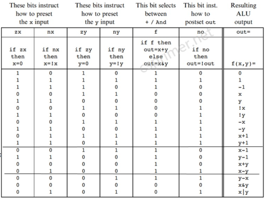
ALU在六个控制输入不同的组合下可以实现不同的个功能:comp域六位对应zx,nx,zy,ny,f,no
if可以使用多路选择器来进行判断,ALU数据通路图:
Or16way
/**
 * 16-way Or:
 * out = (in[0] or in[1] or ... or in[15])
 */

module Or16Way(input[15:0] in,output out);
    // your code here
wire out1,out2,out3,out4,out5,out6,out7,out8,out9,out10,out11,out12,out13,out14;
     Or g1(in[0],in[1],out1);
    Or g2(out1,in[2],out2);
    Or g3(out2,in[3],out3);
    Or g4(out3,in[4],out4);
    Or g5(out4,in[5],out5);
    Or g6(out5,in[6],out6);
    Or g7(out6,in[7],out7);
    Or g8(out7,in[8],out8);
    Or g9(out8,in[9],out9);
    Or g10(out9,in[10],out10);
    Or g11(out10,in[11],out11);
    Or g12(out11,in[12],out12);
    Or g13(out12,in[13],out13);
    Or g14(out13,in[14],out14);
    Or g15(out14,in[15],out);

endmodule
IsNeg
module IsNeg(input[15:0] in, output out);
  // your code here
 Or g1(in[15],1'b0,out);

endmodule
ALU
/**
 * The ALU (Arithmetic Logic Unit).
 * Computes one of the following functions:
 * x+y, x-y, y-x, 0, 1, -1, x, y, -x, -y, !x, !y,
 * x+1, y+1, x-1, y-1, x&y, x|y on two 16-bit inputs,
 * according to 6 input bits denoted zx,nx,zy,ny,f,no.
 * In addition, the ALU computes two 1-bit outputs:
 * if the ALU output == 0, zr is set to 1; otherwise zr is set to 0;
 * if the ALU output < 0, ng is set to 1; otherwise ng is set to 0.
 */

// Implementation: the ALU logic manipulates the x and y inputs
// and operates on the resulting values, as follows:
// if (zx == 1) set x = 0        // 16-bit constant
// if (nx == 1) set x = !x       // bitwise not
// if (zy == 1) set y = 0        // 16-bit constant
// if (ny == 1) set y = !y       // bitwise not
// if (f == 1)  set out = x + y  // integer 2's complement addition
// if (f == 0)  set out = x & y  // bitwise and
// if (no == 1) set out = !out   // bitwise not
// if (out == 0) set zr = 1
// if (out < 0) set ng = 1


module ALU(input[15:0] x, y, input zx,nx,zy,ny,f,no, output[15:0] out, output zr, ng);
  wire[15:0] x1, notx1, x2, y1, noty1, y2, andxy, addxy, o1, noto1, o2;
  wire notzr;
  // your code here, use Mux16,Not16,Add16,And16,Or16Way,IsNeg to implement
  // if (zx == 1) set x = 0
	Mux16	g1(x,16'h0,zx,x1);


  // if (nx == 1) set x = !x
	Not16   g2(x1,notx1);
	Mux16   g3(x1,notx1,nx,x2);

  // if (zy == 1) set y = 0
  	Mux16	g4(y,16'h0,zy,y1);

  // if (ny == 1) set y = !y
	Not16   g5(y1,noty1);
	Mux16   g6(y1,noty1,ny,y2);

  // addxy = x + y
  	Add16   g7(x2,y2,addxy);

  // andxy = x & y
  	And16   g8(x2,y2,andxy);

  // if (f == 1)  set out = x + y else set out = x & y
  	Mux16   g9(andxy,addxy,f,o1);

  // if (no == 1) set out = !out
  	Not16   g10(o1,noto1);
	Mux16   g11(o1,noto1,no,out);


  // zr

	Or16Way g12(out,notzr);
	Not g13(notzr,zr);
  // ng
	IsNeg g14(out,ng);

endmodule










【推荐】国内首个AI IDE,深度理解中文开发场景,立即下载体验Trae
【推荐】编程新体验,更懂你的AI,立即体验豆包MarsCode编程助手
【推荐】抖音旗下AI助手豆包,你的智能百科全书,全免费不限次数
【推荐】轻量又高性能的 SSH 工具 IShell:AI 加持,快人一步
· 阿里最新开源QwQ-32B,效果媲美deepseek-r1满血版,部署成本又又又降低了!
· Manus重磅发布:全球首款通用AI代理技术深度解析与实战指南
· 开源Multi-agent AI智能体框架aevatar.ai,欢迎大家贡献代码
· 被坑几百块钱后,我竟然真的恢复了删除的微信聊天记录!
· AI技术革命,工作效率10个最佳AI工具