ESP8266 ADC - Analog Sensors
http://www.instructables.com/id/ESP8266-ADC-Analog-Sensors/?ALLSTEPS
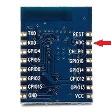
ESP8266 modules have the capacity to perform many useful tasks. GPIO pins can be manipulated based on digital signals to do all sorts of handy things.
Expanded firmware such as NodeMCU have made these modules very flexible and have transformed them into fully capable micro-controllers.
Now, the ESP8266 v7 and v12, include an ADC (Analog digital converter) pin. This means that the ESP8266 module can process inputs from analog sensors. Light sensors, rheostats, force sensors, etc.
This is loosely comparable to an Arduino 'Analog IN' pin.
With an ADC capability, instead of just ON or OFF, the ESP8266 can read a range.
Step 1: Prepare your ESP8266.
My presumption is that you could utilize the ADC pin with the default firmware if you are schooled sufficiently in bit banging. I don't have the knowledge or patience.
NodeMCU has a "read.adc()" function built in. Easy.
So, flash your module with NodeMcu.
I use lualoader with Win7 to flash and manage these modules with good success.
Step 2: Connect the analog device.
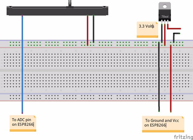
Connect your analog sensor as you would with an Arduino. For testing I am using a generic 10K 'slider' rheostat.
Connect you sensor wire to the ESP's ADC pin.
Step 3: Boot up the ESP
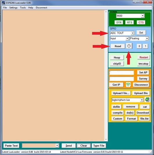
Once booted up, using lualoader, you can read/monitor the ADC TOUT pin. Use either 'read' or 'autorepeat read'. The values will be echoed in the main window.
The datasheet describes the ADC pin as having 10 bit resolution. This means 0 to 1024. You should get a value somewhere within this range.
Here the fun begins! Apparently, the module only converts voltage between 0 and 1 volt.
As an example, I have a 10k rheostat hooked up to the ADC pin. Fully moving the slider to the position where I would expect a 0 reading, the ADC TOUT pins reads 13~15, not 0 but encouraging!
However, as I slide the slider to the right, I see the ADC TOUT reaches the maximum reading of 1024 in about 1/3 the distance.
Ideally, I want the slider to register 0 to 1024 increasing or decreasing over 100% of the slider travel.
Reaching the maximum reading in 1/3 of the travel makes sense, the ADC pin only reads up to 1 volt. Any reading over that, say 1.1v to Vcc of 3.3v will be maxed out to 1024.
So, I need to supply the ADC pin a voltage between 0 and 1 volt only.
Using a voltage divider greatly improves the situation.
Step 4: Add a voltage divider
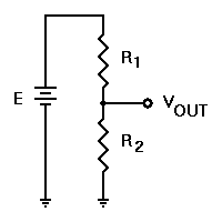
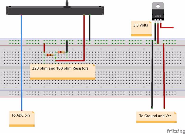
For R1, I used a 220R and for R2, I used 100R resistors. On my voltmeter the actual resistance was 225 and 103.7 respectfully. The math indicates that 220R and 100R should divide 3.3v to 1.03v. 225R and 103.7 should be ~1.04v. All very close. On the breadboard, my voltmeter is reading .98v.
This relationship should hold true for 22R and 10R as well as 20K and 10K. However, caution! the small ones heat up. The larger ones utilize the full range of the slider but the readings are only a few hundred apart.
Using 220R and 100R seem to work, my slider now reads from ~10-13 on the low end to 1024 and the range has a steady progression through 100% of the slider travel.
I suspect that replacing one of these resistors with a trim pot in the same range would give me the ability to fine tune this slider to the full 0 to 1024 range.
Step 5: ADC on an ESP8266-01 ?
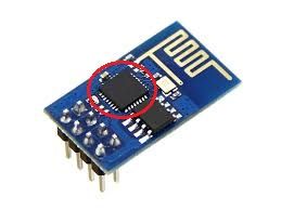
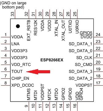
If you are very good with a soldering iron, this ADC capability can be accessed on any version of the ESP8266. The above graphic is the pinout for the EX chip. The chip on the ESP-1 has the pinout, just not the physical connection. Some steady hands and a small iron could tap it.
Some observations that could save you heartburn:
- These modules are not breadboard friendly and not just because the pins are too close together. Simply plugging in a connection lead or bump the tx rx connections can cause errors. Just bumping the breadboard can be problematic. These chips are very sensitive to voltage fluctuations. Hours of hair pulling and chasing the ghost in the machine was solved by soldering as much as possible. Soldered connections have provided a rock solid controller.
- 3.3 volts and lots of it. 630ma. If you use a lm1117t3.3 regulator (I do.) Solder it! If the ground becomes loose or is wiggled, your 3.3v can spike. Over-voltage will cause the ESP to reboot. Too much voltage will cause smoke.
- Coding formats in the NodeMCU api may or may not work in your script. I.e. wifi.sta.setip(), use '=' not ':'.
- You can use your UNO as a serial device, however, your UNO puts out 5v at both the tx and rx pins. Some sources state that the ESP8266's GPIOs are tolerant. tx and rx are not. Use voltage dividers and diodes or some other magic. Besides, if you have to use an Arduino for your project, use an Arduino. As this product matures, perhaps you wont need an Arduino.
- The NodeMCU Server mod has serious memory leaks. These leaks cause the board to reboot when memory gets too low. Insert 'print(node.heap()' in your script and watch the memory reduce as you access the page. As the "Heap" depletes, the ESP will reboot. This memory leak can be greatly reduce or eliminated by resetting all variables to 'nil' at the end of your script. However, if your script terminates early for some reason, the memory is used until 'reset' This may or may not be a problem for your project.
Also, the "Heap" button in LuaLoader, appears to not give accurate memory readings.
There is a great discussion here: tech.scargill.ne
- Pins 4 and 5 as labeled on my ESP-12 are reversed in LuaLoader. That is, if you want to read or switch pin 4, you will need to assign the task to pin 5 in LuaLoader and for pin 5 you will need to assign pin 4.
With the ability to program digital pins, read analog pins, store and run multiple scripts with NodeMCU's firmware. This platform becomes a capable and very economical alternative for your IoT projects.
I hope you have found this instructable helpful


 浙公网安备 33010602011771号