spi概念
一、SPI概念
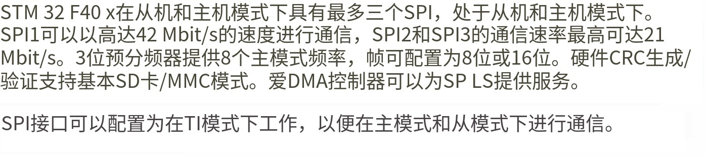
- 串行外设接口(Serial Peripheral Interface)的简称也叫做SPI.
- 是一种高速的、全双工同步通信的一种接口.
- 串行外设接口一般是需要4根线来进行通信(NSS、MISO、MOSI、SCK)。
- 如果打算实现单向通信(最少3根线),就可以利用这种机制实现一对多或者一对一的通信。
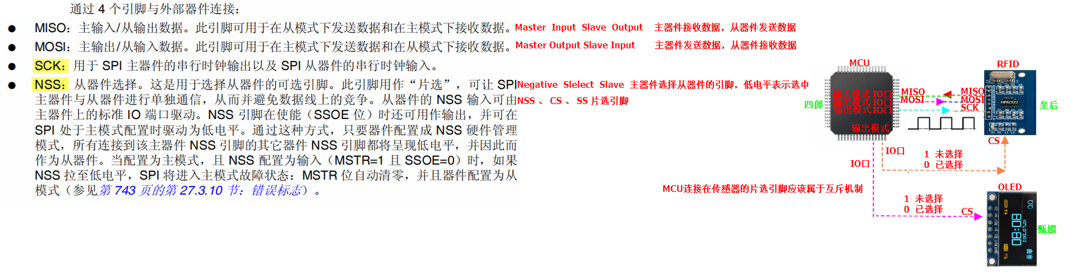
1. 引脚定义
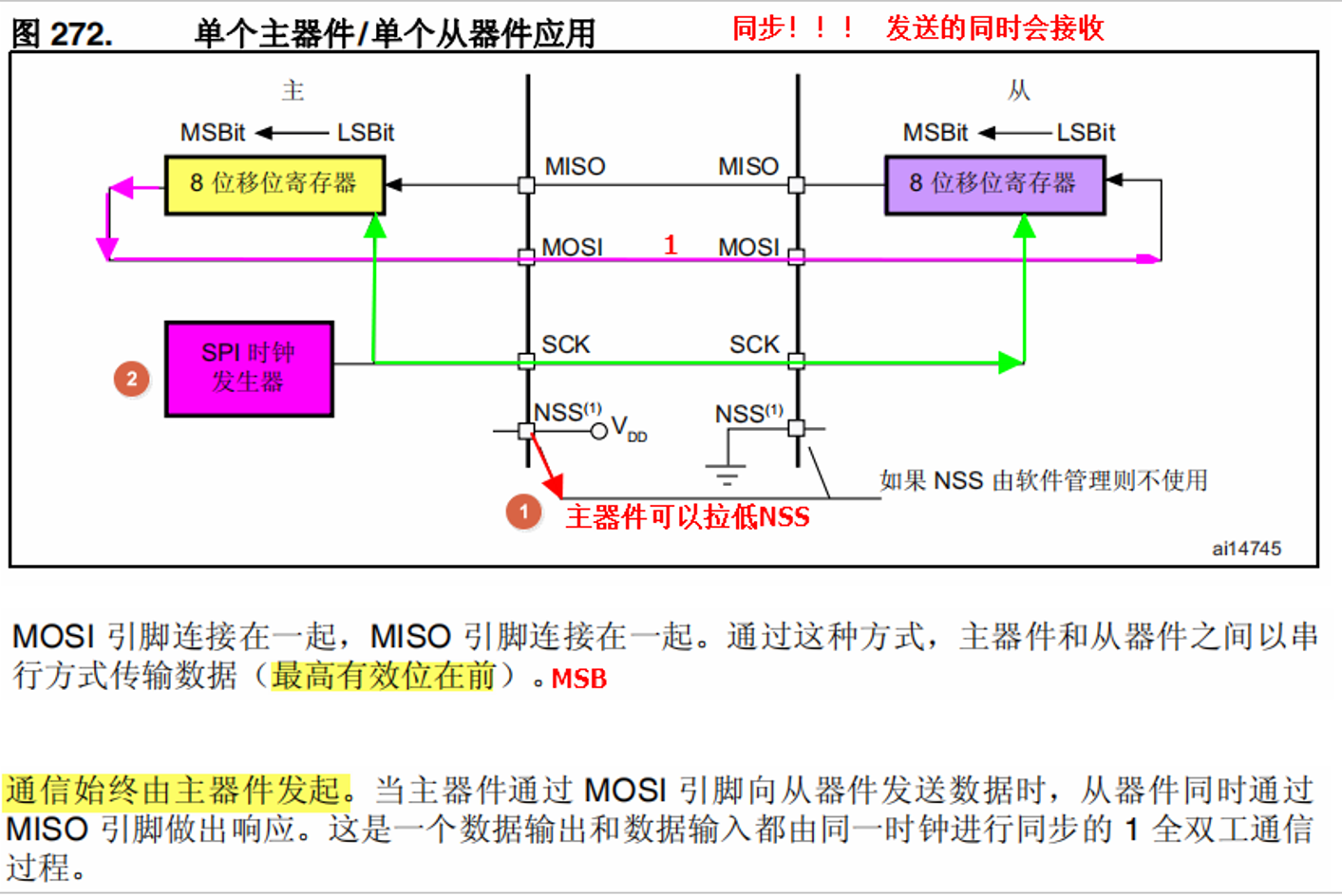
- SPI总线采用的环形结构,利用的是主从模式(主机---->从机)进行数据的传输。
- 由于是同步通信,所以在主机发送数据的同时也会收到从机发送的数据。
2. 数据收发
3. 工作模式
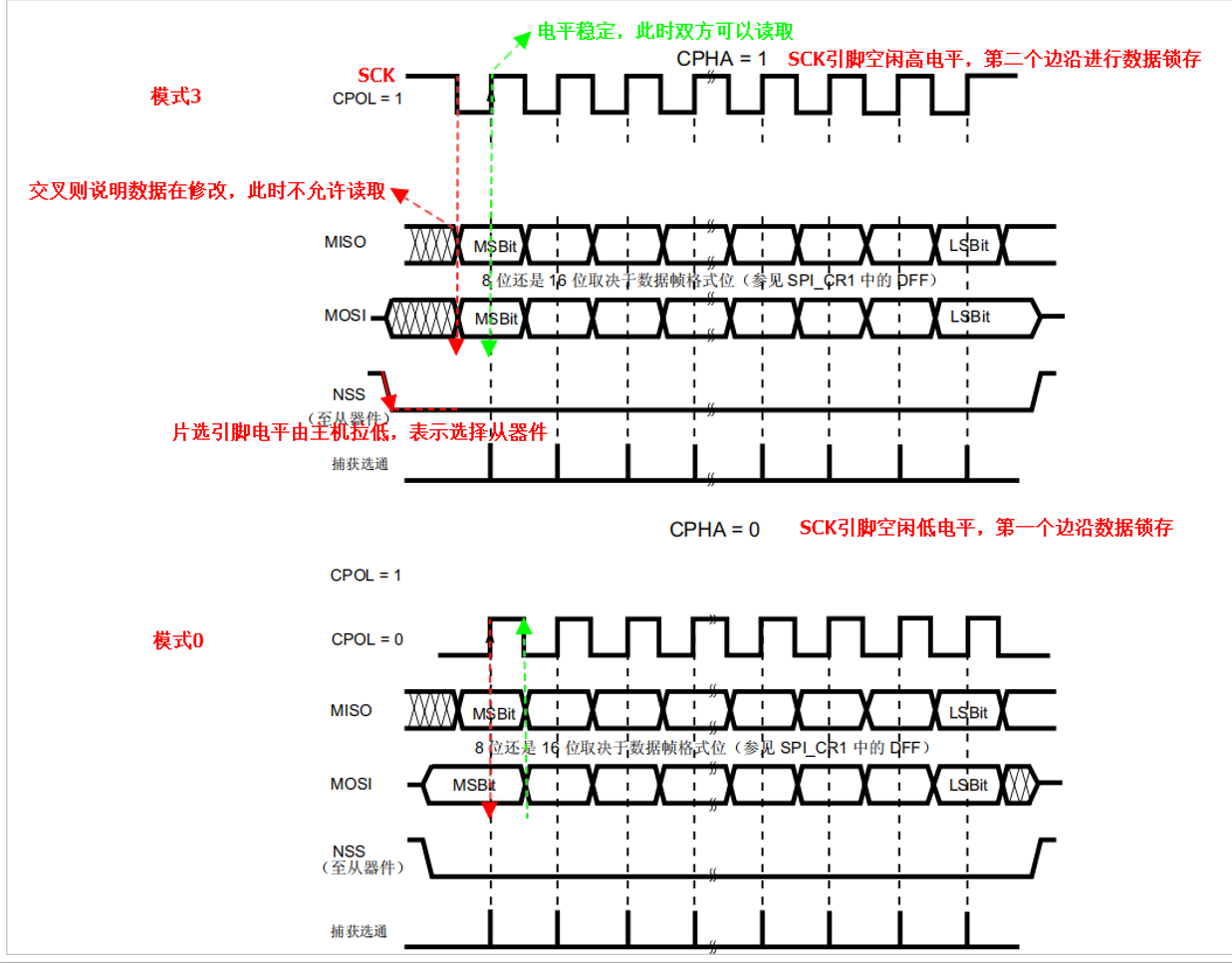
注意:采用SPI接口进行通信,通信双方提前约定好使用哪个工作模式,此时主机可以有4种工作模式可以选择,此时选择哪种模式需要由从器件决定。主机需要配合从机!
绝大多数的采用SPI接口通信的传感器,一般都是支持模式0或者模式3
4. 数据格式
主机与从机在通信的过程中传输的数据时以bit为单位(串行传输),所以数据格式就十分重要,主机的数据格式必须要根据从机的数据格式进行设置(MSB或者LSB),大多数使用SPI接口通信的传感器一般都是使用MSB高位先出。
重要的图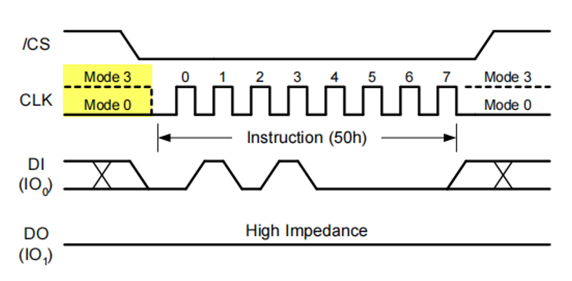
硬件代码
初始化+读取数据
点击查看代码
void W25Q128_Config(void)
{
  SPI_InitTypeDef  SPI_InitStructure;
  GPIO_InitTypeDef GPIO_InitStructure;

  //打开SPI1的时钟
  RCC_APB2PeriphClockCmd(RCC_APB2Periph_SPI1, ENABLE);

  //打开GPIOB端口的时钟
  RCC_AHB1PeriphClockCmd(RCC_AHB1Periph_GPIOB,ENABLE);

  //选择IO口的复用功能
  GPIO_PinAFConfig(GPIOB, GPIO_PinSource3, GPIO_AF_SPI1);		//SCK
  GPIO_PinAFConfig(GPIOB, GPIO_PinSource4, GPIO_AF_SPI1);		//MISO
  GPIO_PinAFConfig(GPIOB, GPIO_PinSource5, GPIO_AF_SPI1);     	//MOSI

  GPIO_InitStructure.GPIO_Mode 	= GPIO_Mode_AF;					//复用模式
  GPIO_InitStructure.GPIO_Speed = GPIO_Speed_50MHz;
  GPIO_InitStructure.GPIO_OType = GPIO_OType_PP;
  GPIO_InitStructure.GPIO_PuPd  = GPIO_PuPd_DOWN;
  GPIO_InitStructure.GPIO_Pin 	= GPIO_Pin_3|GPIO_Pin_4|GPIO_Pin_5;
  GPIO_Init(GPIOB, &GPIO_InitStructure);

  //配置CS片选引脚  输出模式
  GPIO_InitStructure.GPIO_Pin 	= GPIO_Pin_14;
  GPIO_InitStructure.GPIO_Mode 	= GPIO_Mode_OUT;
  GPIO_InitStructure.GPIO_OType = GPIO_OType_PP;
  GPIO_InitStructure.GPIO_Speed = GPIO_Speed_50MHz;
  GPIO_InitStructure.GPIO_PuPd 	= GPIO_PuPd_NOPULL;
  GPIO_Init(GPIOB, &GPIO_InitStructure);

  //片选引脚,空闲状态为高电平
  W25Q128_CS(1);

  //配置SPI1  W25Q128存储IC支持模式0和模式3
  SPI_InitStructure.SPI_Direction = SPI_Direction_2Lines_FullDuplex;	//全双工
  SPI_InitStructure.SPI_Mode = SPI_Mode_Master;							//主模式
  SPI_InitStructure.SPI_DataSize = SPI_DataSize_8b;						//8bit数据位
  SPI_InitStructure.SPI_CPOL = SPI_CPOL_High;							//时钟极性  1
  SPI_InitStructure.SPI_CPHA = SPI_CPHA_2Edge;							//时钟相位  1    11 --模式3
  SPI_InitStructure.SPI_NSS = SPI_NSS_Soft;								//软件控制CS片选
  SPI_InitStructure.SPI_BaudRatePrescaler = SPI_BaudRatePrescaler_4;

  SPI_InitStructure.SPI_FirstBit = SPI_FirstBit_MSB;					//高位先出
  SPI_Init(SPI1, &SPI_InitStructure);

  //使能SPI1
  SPI_Cmd(SPI1, ENABLE);

}

//发送一个字节,并且会得到一个字节
uint8_t W25Q128_SendByte(uint8_t byte)
{
  /*!< Loop while DR register in not emplty */
  while (SPI_I2S_GetFlagStatus(SPI1, SPI_I2S_FLAG_TXE) == RESET);

  /*!< Send byte through the SPI1 peripheral */
  SPI_I2S_SendData(SPI1, byte);

  /*!< Wait to receive a byte */
  while (SPI_I2S_GetFlagStatus(SPI1, SPI_I2S_FLAG_RXNE) == RESET);

  /*!< Return the byte read from the SPI bus */
  return SPI_I2S_ReceiveData(SPI1);
}
模拟spi
点击查看代码
发送一个字节,并且会得到一个字节    假设采用模式3   SCK引脚空闲高电平,第二个边沿锁存数据
uint8_t W25Q128_SendByte(uint8_t byte)
{
	int i = 0;
	uint8_t data = 0;

	 //1.SCK引脚输出高电平
	 W25Q128_SCK(1);
	 delay_us(5);

	 //3.循环发送8次,每次发送一个bit  遵循MSB 高位先出
	 for(i=0;i<8;i++)
	 {
		  //2.SCK引脚输出低电平,此时第一个边沿出现
			W25Q128_SCK(0);
			delay_us(5);

		 //4.判断待发送的字节的最高位  ???? ???? & 1000 0000
		 if( byte & 0x80 )
		 {
				W25Q128_MOSI(1);
		 }
		 else
				W25Q128_MOSI(0);

		 byte <<= 1;
		 delay_us(5);

		 //5.SCK引脚输出高电平,此时第二个边沿出现
		 W25Q128_SCK(1);
		 delay_us(5);

		 //6.此时从机会响应一个bit,主机需要接收!
		 data <<= 1;
		 data |= W25Q128_MISO;
		 delay_us(5);
	 }

	 return data;
}