双目标定,匹配的笔记
清华大学黄耀的Stereo-Matching-Introduction ppt
Efficient Large-scale Stereo Matching
Stereo Calibration and Rectification
双目摄像头矫正就是为了
- 极点在无穷远处
- 对应的极线水平对齐
做法是:
旋转左右相机使得他们看起来是在一个平面上面的,并且使得他们对应的极线是水平对其的,最后进行scale缩放使得水平的畸变最小
大概的公式是这样的,定义左摄像头作为世界参考坐标系,\(P_l\)是一个点p在世界坐标系表示,\(P_r\)是该点在右摄像机坐标系中表示,R,T是左右摄像机的坐标变换,那么有
上面对他们同时乘以一个\(R_{rect}\),要是\(R_{rect}T = \{|T| \quad 0 \quad 0\}\)
那么同一点p在左右摄像机中的表示只是相差一个x值,就是在同一水平线上,那么\(R_{rect}\)怎么构造呢
大概就是以摄像机的中心连线作为\(e_1\),\(e_1\)叉乘一个相机的光心轴的方向作为\(e_2\),\(e_3\) 就是\(e_1\)叉乘\(e_2\), \(e_1,e_2,e_3\)就是\(R_{rect}\)
具体可以参考上面的那个Stereo Calibration and Rectification,对opencv stereo代码的使用还有原理讲解非常好。
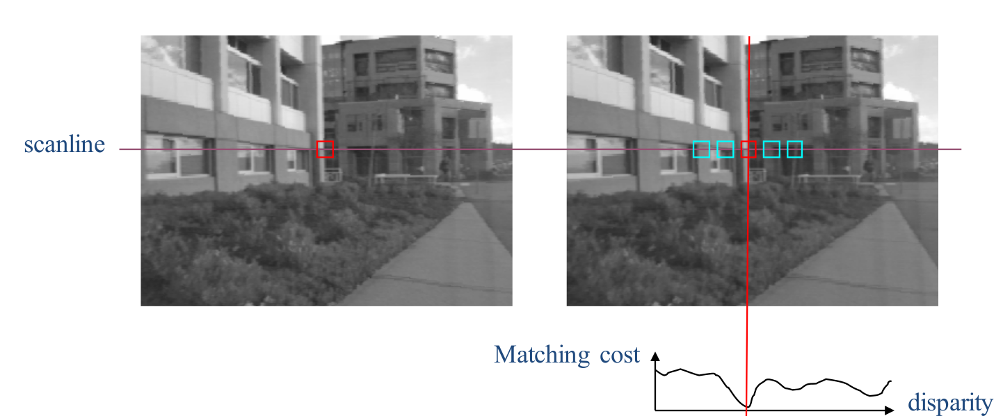
左右图像已经矫正,搜索就是在同一行上面进行,一般有local window search, global energy function
- Local Approach
最简单的做法是下面这种

for each row, k
	for j = Δ to w
		c min = ∞
		for d = 0 to Δ // check each possible disparity
			c(d) = f ( I 1 (j,k), I 2 (j-d,k) )
			if c(d) < c min then
				d best = d
				c min = c(d)
		disp( j,k ) = d best // Save best d value
就是利用局部像素的信息,有滑动窗口,NCC 什么的,但是对于边缘的地方效果不是很好,还有就是窗口的大小对效果很有关系

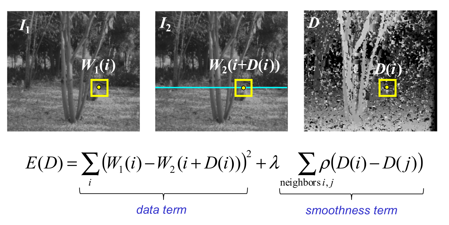
- Global Approach

就是加了一项平滑的量
立体匹配具体的可以参考上面的黄耀的Stereo-Matching-Introduction
评价算法好坏的可以从以下几个方面:
对边界处深度的估计,无纹理地方的估计,渐变面的深度估计,遮掩地方的估计,还有需要计算的时间,内存
双目标定的代码
是别人的代码,具体的来源我忘了(对不住了兄弟,知道的可以跟我说一下,我给个链接)
// stereoCalibration.cpp : 定义控制台应用程序的入口点。
//
//在进行双目摄像头的标定之前,最好事先分别对两个摄像头进行单目视觉的标定
//分别确定两个摄像头的内参矩阵,然后再开始进行双目摄像头的标定
//在此例程中是先对两个摄像头进行单独标定(见上一篇单目标定文章),然后在进行立体标定

#include "stdio.h"
#include <opencv2/opencv.hpp>
#include <opencv2/highgui/highgui.hpp>
#include "cv.h"
#include <cv.hpp>
#include <iostream>

using namespace std;
using namespace cv;

const int imageWidth = 672;								//摄像头的分辨率
const int imageHeight = 376;
const int boardWidth = 11;								//横向的角点数目
const int boardHeight = 8;								//纵向的角点数据
const int boardCorner = boardWidth * boardHeight;		//总的角点数据
const int frameNumber = 40;								//相机标定时需要采用的图像帧数
const int squareSize = 20;								//标定板黑白格子的大小 单位mm
const Size boardSize = Size(boardWidth, boardHeight);	//
Size imageSize = Size(imageWidth, imageHeight);

Mat R, T, E, F;											//R 旋转矢量 T平移矢量 E本征矩阵 F基础矩阵
vector<Mat> rvecs;									    //旋转向量
vector<Mat> tvecs;										//平移向量
vector<vector<Point2f>> imagePointL;				    //左边摄像机所有照片角点的坐标集合
vector<vector<Point2f>> imagePointR;					//右边摄像机所有照片角点的坐标集合
vector<vector<Point3f>> objRealPoint;					//各副图像的角点的实际物理坐标集合


vector<Point2f> cornerL;								//左边摄像机某一照片角点坐标集合
vector<Point2f> cornerR;								//右边摄像机某一照片角点坐标集合

Mat rgbImageL, grayImageL;
Mat rgbImageR, grayImageR;

Mat Rl, Rr, Pl, Pr, Q;									//校正旋转矩阵R,投影矩阵P 重投影矩阵Q (下面有具体的含义解释)
Mat mapLx, mapLy, mapRx, mapRy;							//映射表
Rect validROIL, validROIR;								//图像校正之后,会对图像进行裁剪,这里的validROI就是指裁剪之后的区域

/*
事先标定好的左相机的内参矩阵
fx 0 cx
0 fy cy
0 0  1
*/
Mat cameraMatrixL = (Mat_<double>(3, 3) << 350.630987, 0.000000, 338.489358,
0.000000, 350.460123 ,186.370994,
										  0,  0,       1);
Mat distCoeffL = (Mat_<double>(5, 1) << -0.167658 ,0.022202 ,-0.000261 ,-0.000113, 0.000000
);
/*
事先标定好的右相机的内参矩阵
fx 0 cx
0 fy cy
0 0  1
*/
Mat cameraMatrixR = (Mat_<double>(3, 3) << 350.032707, 0.000000 ,352.606748,
0.000000 ,349.998921 ,189.797070,
											0,		0,		 1);
Mat distCoeffR = (Mat_<double>(5, 1) << -0.167346, 0.023118 ,-0.000105, 0.000318, 0.000000);


/*计算标定板上模块的实际物理坐标*/
void calRealPoint(vector<vector<Point3f>>& obj, int boardwidth, int boardheight, int imgNumber, int squaresize)
{
	//	Mat imgpoint(boardheight, boardwidth, CV_32FC3,Scalar(0,0,0));
	vector<Point3f> imgpoint;
	for (int rowIndex = 0; rowIndex < boardheight; rowIndex++)
	{
		for (int colIndex = 0; colIndex < boardwidth; colIndex++)
		{
			//	imgpoint.at<Vec3f>(rowIndex, colIndex) = Vec3f(rowIndex * squaresize, colIndex*squaresize, 0);
			imgpoint.push_back(Point3f(rowIndex * squaresize, colIndex * squaresize, 0));
		}
	}
	for (int imgIndex = 0; imgIndex < imgNumber; imgIndex++)
	{
		obj.push_back(imgpoint);
	}
}

void outputCameraParam(void)
{
	/*保存数据*/
	/*输出数据*/
	FileStorage fs("intrinsics.yml", FileStorage::WRITE);
	if (fs.isOpened())
	{
		fs << "cameraMatrixL" << cameraMatrixL << "cameraDistcoeffL" << distCoeffL <<"cameraMatrixR" << cameraMatrixR << "cameraDistcoeffR" << distCoeffR;
		fs.release();
		cout << "cameraMatrixL=:" << cameraMatrixL <<endl<< "cameraDistcoeffL=:" << distCoeffL <<endl<<"cameraMatrixR=:" << cameraMatrixR <<endl<< "cameraDistcoeffR=:" << distCoeffR<<endl;
	}
	else
	{
		cout << "Error: can not save the intrinsics!!!!!" << endl;
	}

	fs.open("extrinsics.yml", FileStorage::WRITE);
	if (fs.isOpened())
	{
		fs << "R" << R << "T" << T << "Rl" << Rl << "Rr" << Rr << "Pl" << Pl << "Pr" << Pr << "Q" << Q;
		cout << "R=" << R << endl << "T=" << T << endl << "Rl=" << Rl << endl << "Rr=" << Rr << endl << "Pl=" << Pl << endl << "Pr=" << Pr << endl << "Q=" << Q << endl;
		fs.release();
	}
	else
		cout << "Error: can not save the extrinsic parameters\n";
}


int main(int argc, char* argv[])
{
	Mat img;
	int goodFrameCount = 0;
	namedWindow("ImageL");
	namedWindow("ImageR");
	cout << "按Q退出 ..." << endl;
	while (goodFrameCount < frameNumber)
	{
		char filename[100];
		/*读取左边的图像*/
		sprintf(filename, "image/left-%04d.png", goodFrameCount + 1);
		rgbImageL = imread(filename, CV_LOAD_IMAGE_COLOR);
		cvtColor(rgbImageL, grayImageL, CV_BGR2GRAY);

		/*读取右边的图像*/
		sprintf(filename, "image/right-%04d.png", goodFrameCount + 1);
		rgbImageR = imread(filename, CV_LOAD_IMAGE_COLOR);
		cvtColor(rgbImageR, grayImageR, CV_BGR2GRAY);

		bool isFindL, isFindR;

		isFindL = findChessboardCorners(rgbImageL, boardSize, cornerL);
		isFindR = findChessboardCorners(rgbImageR, boardSize, cornerR);
		if (isFindL == true && isFindR == true)	 //如果两幅图像都找到了所有的角点 则说明这两幅图像是可行的
		{
			/*
			Size(5,5) 搜索窗口的一半大小
			Size(-1,-1) 死区的一半尺寸
			TermCriteria(CV_TERMCRIT_EPS | CV_TERMCRIT_ITER, 20, 0.1)迭代终止条件
			*/
			cornerSubPix(grayImageL, cornerL, Size(5, 5), Size(-1, -1), TermCriteria(CV_TERMCRIT_EPS | CV_TERMCRIT_ITER, 20, 0.1));
			drawChessboardCorners(rgbImageL, boardSize, cornerL, isFindL);
			imshow("chessboardL", rgbImageL);
			imagePointL.push_back(cornerL);


			cornerSubPix(grayImageR, cornerR, Size(5, 5), Size(-1, -1), TermCriteria(CV_TERMCRIT_EPS | CV_TERMCRIT_ITER, 20, 0.1));
			drawChessboardCorners(rgbImageR, boardSize, cornerR, isFindR);
			imshow("chessboardR", rgbImageR);
			imagePointR.push_back(cornerR);

			/*
			本来应该判断这两幅图像是不是好的,如果可以匹配的话才可以用来标定
			但是在这个例程当中,用的图像是系统自带的图像,都是可以匹配成功的。
			所以这里就没有判断
			*/
			//string filename = "res\\image\\calibration";
			//filename += goodFrameCount + ".jpg";
			//cvSaveImage(filename.c_str(), &IplImage(rgbImage));		//把合格的图片保存起来
			goodFrameCount++;
			cout << "The image is good" << endl;
		}
		else
		{
			cout << "The image is bad please try again" << endl;
		}

		if (waitKey(10) == 'q')
		{
			break;
		}
	}

	/*
	计算实际的校正点的三维坐标
	根据实际标定格子的大小来设置
	*/
	calRealPoint(objRealPoint, boardWidth, boardHeight, frameNumber, squareSize);
	cout << "cal real successful" << endl;

	/*
		标定摄像头
		由于左右摄像机分别都经过了单目标定
		所以在此处选择flag = CALIB_USE_INTRINSIC_GUESS
	*/
	double rms = stereoCalibrate(objRealPoint, imagePointL, imagePointR,
		cameraMatrixL, distCoeffL,
		cameraMatrixR, distCoeffR,
		Size(imageWidth, imageHeight), R, T, E, F,
		CALIB_USE_INTRINSIC_GUESS,
		TermCriteria(TermCriteria::COUNT + TermCriteria::EPS, 100, 1e-5));

	cout << "Stereo Calibration done with RMS error = " << rms << endl;

	/*
	立体校正的时候需要两幅图像共面并且行对准 以使得立体匹配更加的可靠
	使得两幅图像共面的方法就是把两个摄像头的图像投影到一个公共成像面上,这样每幅图像从本图像平面投影到公共图像平面都需要一个旋转矩阵R
	stereoRectify 这个函数计算的就是从图像平面投影都公共成像平面的旋转矩阵Rl,Rr。 Rl,Rr即为左右相机平面行对准的校正旋转矩阵。
	左相机经过Rl旋转,右相机经过Rr旋转之后,两幅图像就已经共面并且行对准了。
	其中Pl,Pr为两个相机的投影矩阵,其作用是将3D点的坐标转换到图像的2D点的坐标:P*[X Y Z 1]' =[x y w]
	Q矩阵为重投影矩阵,即矩阵Q可以把2维平面(图像平面)上的点投影到3维空间的点:Q*[x y d 1] = [X Y Z W]。其中d为左右两幅图像的时差
	*/
	stereoRectify(cameraMatrixL, distCoeffL, cameraMatrixR, distCoeffR, imageSize, R, T, Rl, Rr, Pl, Pr, Q,
				  CALIB_ZERO_DISPARITY,-1,imageSize,&validROIL,&validROIR);
	/*
	根据stereoRectify 计算出来的R 和 P 来计算图像的映射表 mapx,mapy
	mapx,mapy这两个映射表接下来可以给remap()函数调用,来校正图像,使得两幅图像共面并且行对准
	ininUndistortRectifyMap()的参数newCameraMatrix就是校正后的摄像机矩阵。在openCV里面,校正后的计算机矩阵Mrect是跟投影矩阵P一起返回的。
	所以我们在这里传入投影矩阵P,此函数可以从投影矩阵P中读出校正后的摄像机矩阵
	*/
	initUndistortRectifyMap(cameraMatrixL, distCoeffL, Rl, Pr, imageSize, CV_32FC1, mapLx, mapLy);
	initUndistortRectifyMap(cameraMatrixR, distCoeffR, Rr, Pr, imageSize, CV_32FC1, mapRx, mapRy);


	Mat rectifyImageL, rectifyImageR;
	cvtColor(grayImageL, rectifyImageL, CV_GRAY2BGR);
	cvtColor(grayImageR, rectifyImageR, CV_GRAY2BGR);

	imshow("Rectify Before", rectifyImageL);

	/*
	经过remap之后,左右相机的图像已经共面并且行对准了
	*/
	remap(rectifyImageL, rectifyImageL, mapLx, mapLy, INTER_LINEAR);
	remap(rectifyImageR, rectifyImageR, mapRx, mapRy, INTER_LINEAR);

	imshow("ImageL", rectifyImageL);
	imshow("ImageR", rectifyImageR);

	/*保存并输出数据*/
	outputCameraParam();

	/*
		把校正结果显示出来
		把左右两幅图像显示到同一个画面上
		这里只显示了最后一副图像的校正结果。并没有把所有的图像都显示出来
	*/
	Mat canvas;
	double sf;
	int w, h;
	sf = 600. / MAX(imageSize.width, imageSize.height);
	w = cvRound(imageSize.width * sf);
	h = cvRound(imageSize.height * sf);
	canvas.create(h, w * 2, CV_8UC3);

	/*左图像画到画布上*/
	Mat canvasPart = canvas(Rect(w*0, 0, w, h));								//得到画布的一部分
	resize(rectifyImageL, canvasPart, canvasPart.size(), 0, 0, INTER_AREA);		//把图像缩放到跟canvasPart一样大小
	Rect vroiL(cvRound(validROIL.x*sf), cvRound(validROIL.y*sf),				//获得被截取的区域
		      cvRound(validROIL.width*sf), cvRound(validROIL.height*sf));
	rectangle(canvasPart, vroiL, Scalar(0, 0, 255), 3, 8);						//画上一个矩形

	cout << "Painted ImageL" << endl;

	/*右图像画到画布上*/
	canvasPart = canvas(Rect(w, 0, w, h));										//获得画布的另一部分
	resize(rectifyImageR, canvasPart, canvasPart.size(), 0, 0, INTER_LINEAR);
	Rect vroiR(cvRound(validROIR.x * sf), cvRound(validROIR.y*sf),
			  cvRound(validROIR.width * sf), cvRound(validROIR.height * sf));
	rectangle(canvasPart, vroiR, Scalar(0, 255, 0), 3, 8);

	cout << "Painted ImageR" << endl;

	/*画上对应的线条*/
	for (int i = 0; i < canvas.rows;i+=16)
		line(canvas, Point(0, i), Point(canvas.cols, i), Scalar(0, 255, 0), 1, 8);

	imshow("rectified", canvas);

	cout << "wait key" << endl;
	waitKey(0);
	system("pause");
	return 0;
}
stereoRectify只需要K1,D1,K2,D2,就可以求出R1,P1,R2,P2,Q. 不同的参数alpha会导致的不同的结果,可以把上面的alpha改为-1或者0,试试
stereoCalibrate这个才是矫正得到不同于单目摄像头矫正得到的K1,D1,K2,D2,还有R,T,E,F。
矫正过程中多次取图片的用处不是在重复运行上面两个函数,而是得到多组不同的objectPoints以及对应的imagePoints


