STM32 F4 DAC DMA Waveform Generator
STM32 F4 DAC DMA Waveform Generator
Goal: generating an arbitrary periodic waveform using a DAC with DMA and TIM6 as a trigger.
Agenda:
- Modeling a waveform in MATLAB and getting the waveform data
- Studying the DAC, DMA, and TIM6 to see how it can be used to generate a waveform
- Coding and testing a couple of functions
%% Generating an n-bit sine wave
% Modifiable parameters: step, bits, offset
close; clear; clc;

points = 128;                            % number of points between sin(0) to sin(2*pi)
bits   = 12;                             % 12-bit sine wave for 12-bit DAC
offset = 75;                             % limiting DAC output voltage

t = 0:((2*pi/(points-1))):(2*pi);        % creating a vector from 0 to 2*pi
y = sin(t);                              % getting the sine values
y = y + 1;                               % getting rid of negative values (shifting up by 1)
y = y*((2^bits-1)-2*offset)/2+offset;    % limiting the range (0+offset) to (2^bits-offset)
y = round(y);                            % rounding the values
plot(t, y); grid                         % plotting for visual confirmation

fprintf('%d, %d, %d, %d, %d, %d, %d, %d, %d, %d, \n', y);

There's a trade-off between the sine wave resolution (number of points from sin(0) to sin(2*pi)), output frequency range, and precision of the output frequency (e.g. we want a 20kHz wave, but we can only get 19.8kHz or 20.2kHz because the step is 0.4kHz). The output frequency is a non-linear function with multiple variables. To complicate it further, some of these variables must be integers within 1 to 65535 range which makes it impossible to output certain frequencies precisely.
Although precise frequency control is terribly hard (if not impossible), one feature does stand out - ability to generate a periodic waveform of any shape.
Below is the code for mediocre range/precision/resolution but excellent versatility in terms of shaping the output waveform.
@input - uint16_t function[waveform_resolution]
@output - PA4 in analog configuration
@parameters - OUT_FREQ, SIN_RES
To tailor other parameters, study the DAC channel block diagram, electrical characteristics, timing diagrams, etc. To switch DAC channels, see memory map, specifically DAC DHRx register for DMA writes.
#include <stm32f4xx.h>
#include "other_stuff.h"

#define   OUT_FREQ          5000                                 // Output waveform frequency
#define   SINE_RES          128                                  // Waveform resolution
#define   DAC_DHR12R1_ADDR  0x40007408                           // DMA writes into this reg on every request
#define   CNT_FREQ          42000000                             // TIM6 counter clock (prescaled APB1)
#define   TIM_PERIOD        ((CNT_FREQ)/((SINE_RES)*(OUT_FREQ))) // Autoreload reg value

const uint16_t function[SINE_RES] = { 2048, 2145, 2242, 2339, 2435, 2530, 2624, 2717, 2808, 2897,
                                      2984, 3069, 3151, 3230, 3307, 3381, 3451, 3518, 3581, 3640,
                                      3696, 3748, 3795, 3838, 3877, 3911, 3941, 3966, 3986, 4002,
                                      4013, 4019, 4020, 4016, 4008, 3995, 3977, 3954, 3926, 3894,
                                      3858, 3817, 3772, 3722, 3669, 3611, 3550, 3485, 3416, 3344,
                                      3269, 3191, 3110, 3027, 2941, 2853, 2763, 2671, 2578, 2483,
                                      2387, 2291, 2194, 2096, 1999, 1901, 1804, 1708, 1612, 1517,
                                      1424, 1332, 1242, 1154, 1068, 985, 904, 826, 751, 679,
                                      610, 545, 484, 426, 373, 323, 278, 237, 201, 169,
                                      141, 118, 100, 87, 79, 75, 76, 82, 93, 109,
                                      129, 154, 184, 218, 257, 300, 347, 399, 455, 514,
                                      577, 644, 714, 788, 865, 944, 1026, 1111, 1198, 1287,
                                      1378, 1471, 1565, 1660, 1756, 1853, 1950, 2047 };

static void TIM6_Config(void);
static void DAC1_Config(void);

int main()
{
  GPIO_InitTypeDef gpio_A;

  RCC_AHB1PeriphClockCmd(RCC_AHB1Periph_GPIOA, ENABLE);
  RCC_APB1PeriphClockCmd(RCC_APB1Periph_DAC, ENABLE);
  RCC_AHB1PeriphClockCmd(RCC_AHB1Periph_DMA1, ENABLE);

  gpio_A.GPIO_Pin  = GPIO_Pin_4;
  gpio_A.GPIO_Mode = GPIO_Mode_AN;
  gpio_A.GPIO_PuPd = GPIO_PuPd_NOPULL;
  GPIO_Init(GPIOA, &gpio_A);

  TIM6_Config();
  DAC1_Config();

  while (1)
  {

  }

}

static void TIM6_Config(void)
{
  TIM_TimeBaseInitTypeDef TIM6_TimeBase;

  RCC_APB1PeriphClockCmd(RCC_APB1Periph_TIM6, ENABLE);

  TIM_TimeBaseStructInit(&TIM6_TimeBase);
  TIM6_TimeBase.TIM_Period        = (uint16_t)TIM_PERIOD;
  TIM6_TimeBase.TIM_Prescaler     = 0;
  TIM6_TimeBase.TIM_ClockDivision = 0;
  TIM6_TimeBase.TIM_CounterMode   = TIM_CounterMode_Up;
  TIM_TimeBaseInit(TIM6, &TIM6_TimeBase);
  TIM_SelectOutputTrigger(TIM6, TIM_TRGOSource_Update);

  TIM_Cmd(TIM6, ENABLE);
}

static void DAC1_Config(void)
{
  DAC_InitTypeDef DAC_INIT;
  DMA_InitTypeDef DMA_INIT;

  DAC_INIT.DAC_Trigger        = DAC_Trigger_T6_TRGO;
  DAC_INIT.DAC_WaveGeneration = DAC_WaveGeneration_None;
  DAC_INIT.DAC_OutputBuffer   = DAC_OutputBuffer_Enable;
  DAC_Init(DAC_Channel_1, &DAC_INIT);

  DMA_DeInit(DMA1_Stream5);
  DMA_INIT.DMA_Channel            = DMA_Channel_7;
  DMA_INIT.DMA_PeripheralBaseAddr = (uint32_t)DAC_DHR12R1_ADDR;
  DMA_INIT.DMA_Memory0BaseAddr    = (uint32_t)&function;
  DMA_INIT.DMA_DIR                = DMA_DIR_MemoryToPeripheral;
  DMA_INIT.DMA_BufferSize         = SINE_RES;
  DMA_INIT.DMA_PeripheralInc      = DMA_PeripheralInc_Disable;
  DMA_INIT.DMA_MemoryInc          = DMA_MemoryInc_Enable;
  DMA_INIT.DMA_PeripheralDataSize = DMA_PeripheralDataSize_HalfWord;
  DMA_INIT.DMA_MemoryDataSize     = DMA_MemoryDataSize_HalfWord;
  DMA_INIT.DMA_Mode               = DMA_Mode_Circular;
  DMA_INIT.DMA_Priority           = DMA_Priority_High;
  DMA_INIT.DMA_FIFOMode           = DMA_FIFOMode_Disable;
  DMA_INIT.DMA_FIFOThreshold      = DMA_FIFOThreshold_HalfFull;
  DMA_INIT.DMA_MemoryBurst        = DMA_MemoryBurst_Single;
  DMA_INIT.DMA_PeripheralBurst    = DMA_PeripheralBurst_Single;
  DMA_Init(DMA1_Stream5, &DMA_INIT);

  DMA_Cmd(DMA1_Stream5, ENABLE);
  DAC_Cmd(DAC_Channel_1, ENABLE);
  DAC_DMACmd(DAC_Channel_1, ENABLE);
}
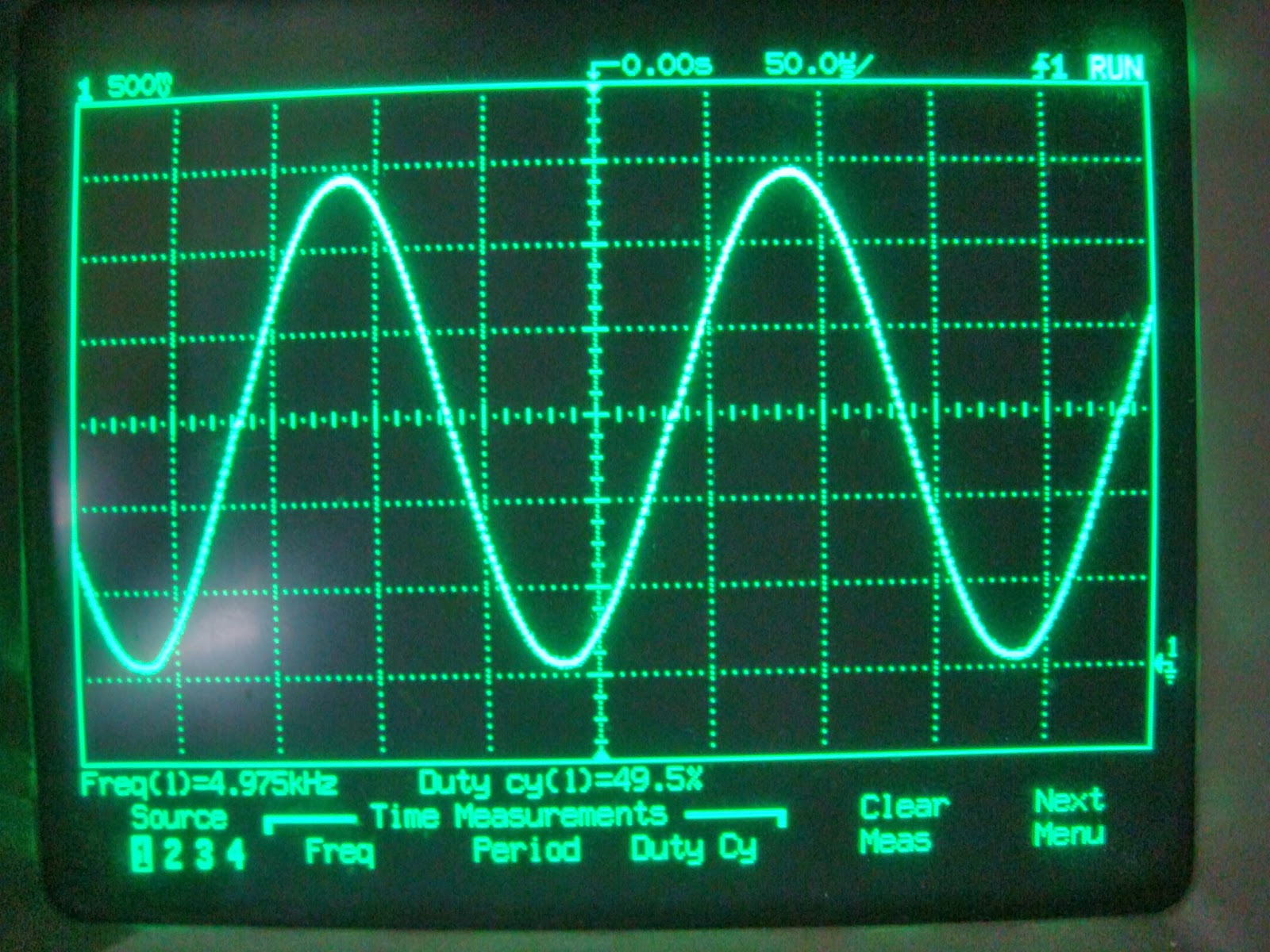
Using the code above we are supposed to get a 5kHz sine wave constructed with 128 points (for better quality, consider using more points).
Here's a picture of what we actually get (off by 25Hz, not too bad).
And here's the cool sinc(x) function. To generate other functions, model it in MATLAB, cast to 12-bit, STM32F4 does the rest.


 浙公网安备 33010602011771号