Driving proportional valves from microcontroller
Driving proportional valves from microcontroller
I am looking to drive a current regulated proportional (solenoid) valve that needs up to 85mA @ 24V from a microcontroller.
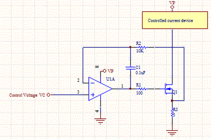
So far I found this circuit that looks pretty straightforward:

What are other low cost options? Is there such a thing as a programmable current source that I can drive through SPI or I2C? So far I wasn't able to find one.
I would drive the valve by PWM with a low side switch. All you need is the transistor and the flyback catch diode. The solenoid coil has significant inductance, so will smooth out the current on its own. I'd stay above the audible range, but most likely the solenoid will "see" only the average well below that frequency. At 25 kHz PWM frequency, for example, you get 40 µS per pulse. That is quite a long time for a modern microcontroller, so you will have plenty of resolution and lots of cycles to compute how long the next pulse should be.
At your voltage and current, you can use something like the IRLML0030 as the low side switch and directly drive it from a digital PWM output of the microcontroller. Don't forget the reverse diode across the coil. A Shottky would be good. 30 V 1 A Shottkys in SMA packages are plentiful and cheap.
You say you want to control the current, but is that really just a internal parameter of a larger control system? For example, are you really trying to control pressure, flow rate, or something else? If the solenoid drive is inside a larger feedback loop, then you can just make the PWM duty cycle proportional to the signal. It won't be completely linear, but plenty close enough for the outer feedback loop to work with and eventually control the desired parameter correctly.
I actually did exactly that once in a real commercial product that controlled the pressure on the output of the valve. I did compensate the duty cycle based on the measured power voltage, since that could vary widely in my case. That means the outer control loop computes the desired solenoid drive level, and the low level code computed the PWM duty cycle from the desired drive level and the actual supply voltage.
I've done a fair number of drivers for proportional valves and find that low PWM frequencies work better - the vibration from the PWM reduces "sticktion" in the valve. This is for both gas pressure valves (large industrial process ovens) and for hydraulic servo valves. Low frequency PWM works way better than either DC or high-frequency PWM. My stuff is usually in the several hundred Hz region. The lower sticktion reduces the hysteresis in the valve. That's been my experience - YMMV
Well, why not make it yourself? Implement this:

Connect PWM with LPF or DAC to voltage input, and You're good to go. To make it robust You can connect feedback to ADC and implement PID driver, so output will be exactly what You desire. It is easy as a pie, first simulate it with LTspice to check ranges and stuff. You don't need to use expensive IC as well, you can go for low frequency high voltage OPAMPS and single 2n7002 fet driven directly from OPAMP.
edit2: WOA? Why do you need such a great mosfet? Is it rated for 80A not mA. Go for small ones, they have way smaller gate capacitance.


【推荐】国内首个AI IDE,深度理解中文开发场景,立即下载体验Trae
【推荐】编程新体验,更懂你的AI,立即体验豆包MarsCode编程助手
【推荐】抖音旗下AI助手豆包,你的智能百科全书,全免费不限次数
【推荐】轻量又高性能的 SSH 工具 IShell:AI 加持,快人一步
· Linux系列:如何用heaptrack跟踪.NET程序的非托管内存泄露
· 开发者必知的日志记录最佳实践
· SQL Server 2025 AI相关能力初探
· Linux系列:如何用 C#调用 C方法造成内存泄露
· AI与.NET技术实操系列(二):开始使用ML.NET
· 被坑几百块钱后,我竟然真的恢复了删除的微信聊天记录!
· 【自荐】一款简洁、开源的在线白板工具 Drawnix
· 没有Manus邀请码?试试免邀请码的MGX或者开源的OpenManus吧
· 园子的第一款AI主题卫衣上架——"HELLO! HOW CAN I ASSIST YOU TODAY
· 无需6万激活码!GitHub神秘组织3小时极速复刻Manus,手把手教你使用OpenManus搭建本
2014-09-04 CMSIS-DAP调试器
2014-09-04 CHM文件无法查看内容解决办法
2014-09-04 HRESULT 0x80131515 解决方法