ARM Memory Compiler 学习
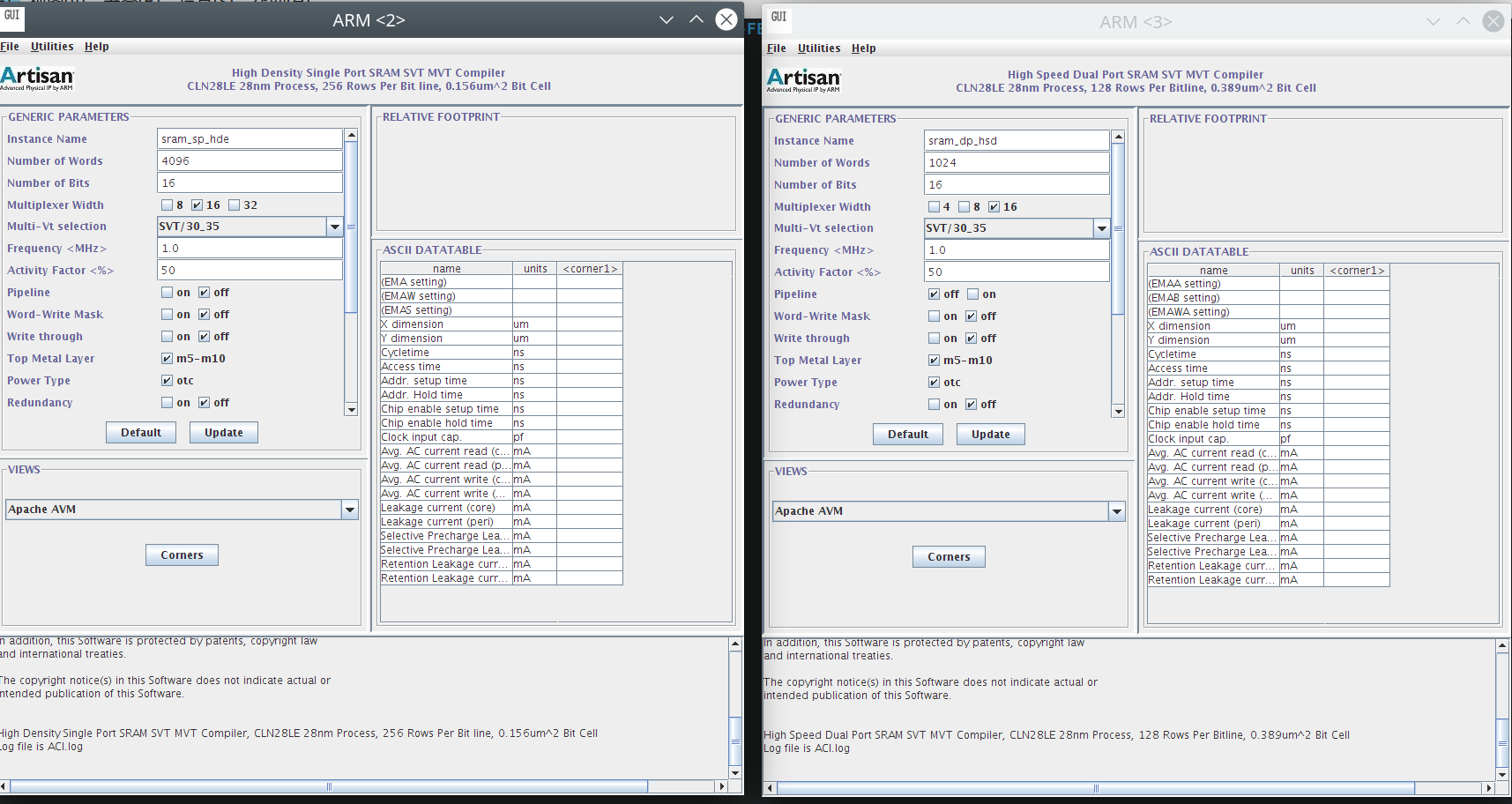
我们一共拿到了两个版本的工具,分别是sram_dp_hsd_svt_mvt和sram_sp_hde_svt_mvt,其中dp是双端口dual port,sp是单端口single port,dp的是hsd,即high speed,sp的是hen即high density,后面的svt_mvt是管子类型。直接找到工具里面的bin,然后运行可执行文件就可以打开gui。
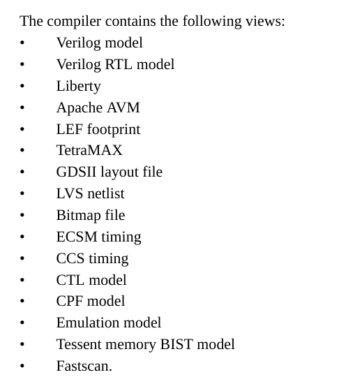
我们看一下这个memory compiler有没有自己的doc可以学习一手。有一本sram_sp_hde_svt_mvt_userguide。
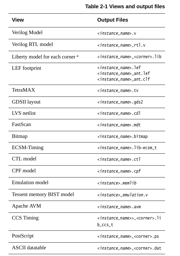
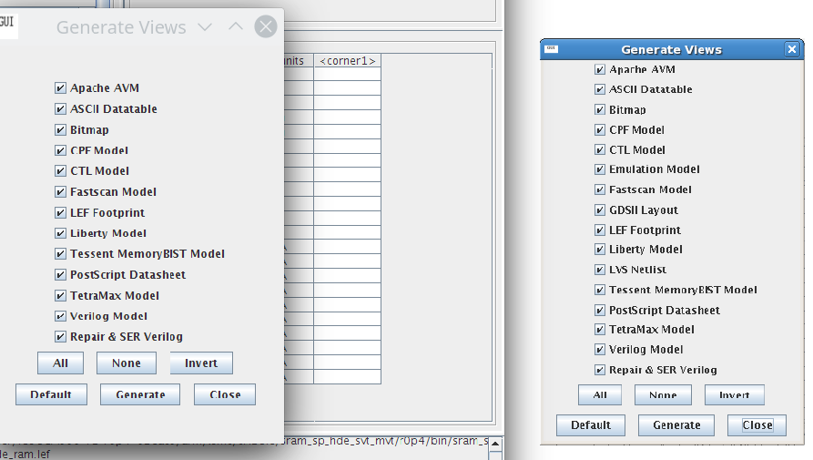
memory compiler能吐出上面的这些文件,其中.v,.lib,.lef,.gds2,.cdl这些都是前后端的常用文件。
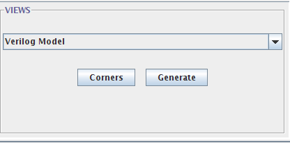
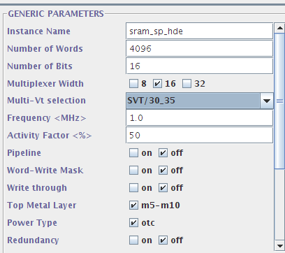
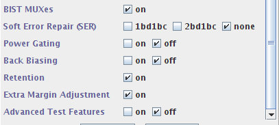
在views这里我们简单选择一个verilog model然后生成一下看看结果。这里的设置是:
整个文件很长,我们先看看文件头:
/* verilog_memcomp Version: c0.3.2-EAC */
/* common_memcomp Version: c0.1.0-EAC */
/* lang compiler Version: 4.1.6-EAC2 Oct 30 2012 16:32:37 */
//
//       CONFIDENTIAL AND PROPRIETARY SOFTWARE OF ARM PHYSICAL IP, INC.
//
//       Copyright (c) 1993 - 2024 ARM Physical IP, Inc.  All Rights Reserved.
//
//       Use of this Software is subject to the terms and conditions of the
//       applicable license agreement with ARM Physical IP, Inc.
//       In addition, this Software is protected by patents, copyright law
//       and international treaties.
//
//       The copyright notice(s) in this Software does not indicate actual or
//       intended publication of this Software.
//
//      Verilog model for High Density Single Port SRAM SVT MVT Compiler
//
//       Instance Name:              sram_sp_hde
//       Words:                      4096
//       Bits:                       16
//       Mux:                        16
//       Drive:                      6
//       Write Mask:                 Off
//       Write Thru:                 Off
//       Extra Margin Adjustment:    On
//       Test Muxes                  On
//       Power Gating:               Off
//       Retention:                  On
//       Pipeline:                   Off
//       Read Disturb Test:	        Off
//
//       Creation Date:  Sun Jan 14 11:45:44 2024
//       Version: 	r0p4_02eac0
//
//      Modeling Assumptions: This model supports full gate level simulation
//          including proper x-handling and timing check behavior.  Unit
//          delay timing is included in the model. Back-annotation of SDF
//          (v3.0 or v2.1) is supported.  SDF can be created utilyzing the delay
//          calculation views provided with this generator and supported
//          delay calculators.  All buses are modeled [MSB:LSB].  All
//          ports are padded with Verilog primitives.
//
//      Modeling Limitations: None.
//
//      Known Bugs: None.
//
//      Known Work Arounds: N/A
//
这里包含了模块的基本信息,比如大小,端口,模块例化名这些,以及模型仿真时的信息,可以看到是支持用sdf后仿真的。
来看一下端口定义,这是我主要关心的信息:
`ifdef POWER_PINS
module sram_sp_hde (VDDCE, VDDPE, VSSE, CENY, WENY, AY, Q, SO, CLK, CEN, WEN, A, D,
    EMA, EMAW, TEN, TCEN, TWEN, TA, TD, RET1N, SI, SE, DFTRAMBYP);
`else
module sram_sp_hde (CENY, WENY, AY, Q, SO, CLK, CEN, WEN, A, D, EMA, EMAW, TEN, TCEN,
    TWEN, TA, TD, RET1N, SI, SE, DFTRAMBYP);
`endif

  parameter ASSERT_PREFIX = "";
  parameter BITS = 16;
  parameter WORDS = 4096;
  parameter MUX = 16;
  parameter MEM_WIDTH = 256; // redun block size 8, 128 on left, 128 on right
  parameter MEM_HEIGHT = 256;
  parameter WP_SIZE = 16 ;
  parameter UPM_WIDTH = 3;
  parameter UPMW_WIDTH = 2;
  parameter UPMS_WIDTH = 0;

  output  CENY;
  output  WENY;
  output [11:0] AY;
  output [15:0] Q;
  output [1:0] SO;
  input  CLK;
  input  CEN;
  input  WEN;
  input [11:0] A;
  input [15:0] D;
  input [2:0] EMA;
  input [1:0] EMAW;
  input  TEN;
  input  TCEN;
  input  TWEN;
  input [11:0] TA;
  input [15:0] TD;
  input  RET1N;
  input [1:0] SI;
  input  SE;
  input  DFTRAMBYP;
`ifdef POWER_PINS
  inout VDDCE;
  inout VDDPE;
  inout VSSE;
`endif
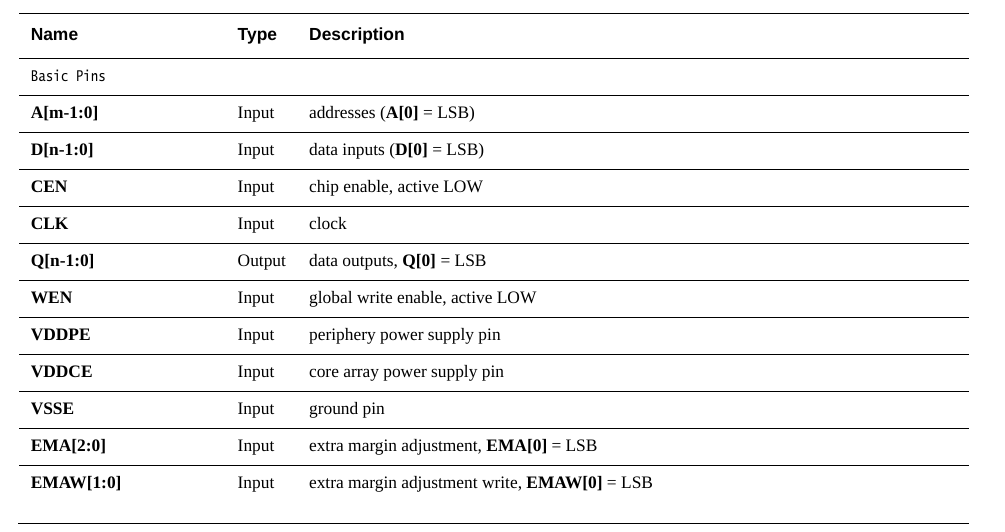
注意这里用了一个POWER_PINS的宏来规定电源引脚VDDCE,VDDPE和VSSE,我不是很懂问什么VDD会有两个,这个回头再看手册,至于数据端口包括了:
| Port | Width | Direction | Function |
|---|---|---|---|
| CLK | 1 | input | clock |
| A | 12 | input | address (A[0]=LSB) |
| D | 16 | input | data inputs (D[0]=LSB) |
| Q | 16 | output | data outputs (Q[0]=LSB) |
| CEN | 1 | input | chip enbale, active LOW |
| WEN | 1 | input | global write enable, active LOW |
这几个信号是我们建模SRAM时的基本信号,此外还有若干个额外的信号:
| Port | Width | Direction | Function |
|---|---|---|---|
| RET1N | 1 | input | retention mode enable1, active LOW |
| EMA | 3 | input | extra margin adjustment, EMA[0]=LSB |
| EMAW | 2 | input | extra margin adjustment write, EMAW[0]=LSB |
| TEN | 1 | input | test mode enable, active LOW. 0=test operation, 1=normal operation |
| TA | 12 | input | address test input, TA[0]=LSB |
| TD | 16 | input | test mode data inputs, TD[0]=LSB |
| TCEN | 1 | input | chip enable test input, active LOW |
| TWEN | 1 | input | write enbale test inputs, active LOW |
| CENY | 1 | output | chip enbale multiplexer output |
| WENY | 1 | output | write enbale multiplexer output |
| AY | 12 | output | address multiplexer output, AY[0]=LSB |
| SO | 2 | output | scan output bus |
| SI | 2 | input | scan input bus |
| SE | 1 | input | scan enable input |
| DFTRAMBYP | 1 | input | test control input |
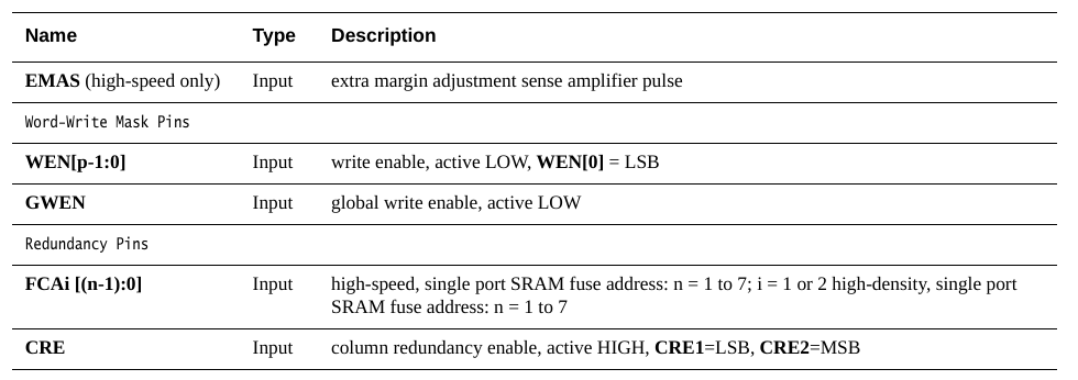
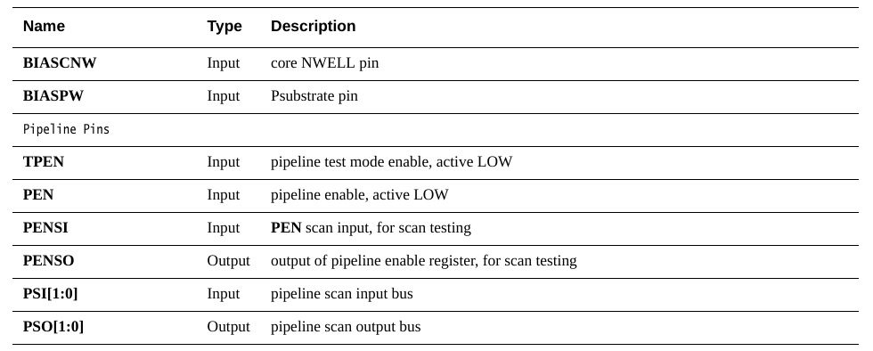
根据手册来看,如果再开一些选项还会有额外的端口产生。
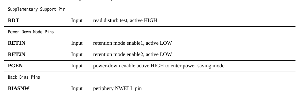
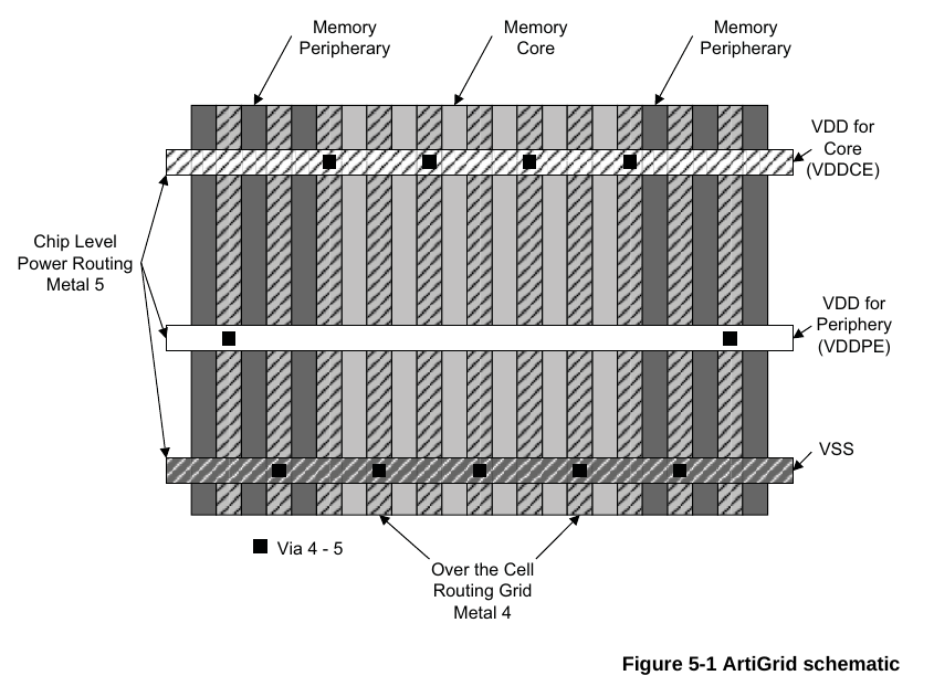
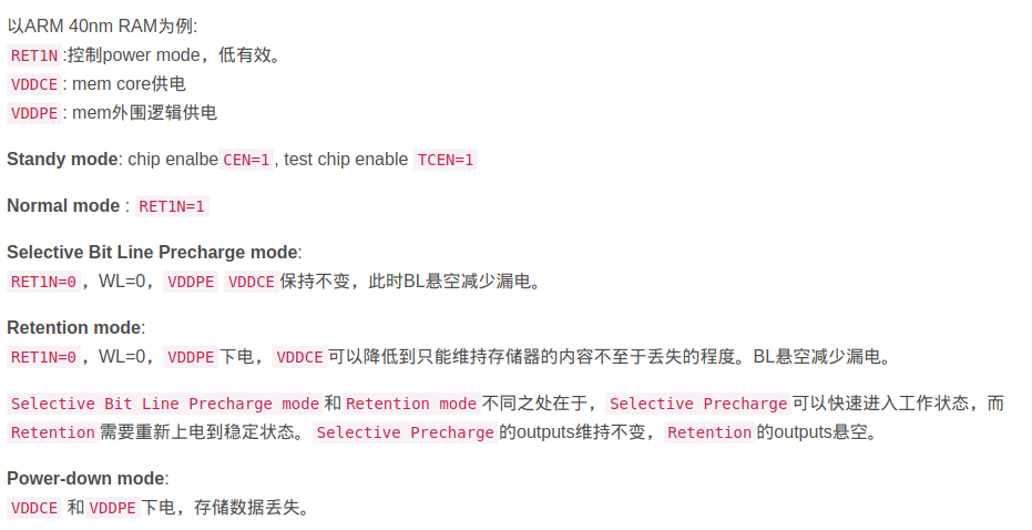
先看一下Power口,VDDPE,VDDCE和VSSE,VSSE就是地,这个没什么好说的,VDDPE是periphery power supply pin,即外围电路的电源,而VDDCE是core array power supply pin,即核心阵列的供电,为什么要分成两个电源,是因为对于低功耗设计来说,在SRAM只需要保持数据不需要进行读写操作时,可以通过VDDPE给关掉,只留VDDCE保持数据。
https://blog.csdn.net/Holden_Liu/article/details/118250226
详细可见下面的描述。另外这里RET1N信号也蹦出来了,是用来辅助低功耗的信号,如果是正常模式,RET1N给1就行了,如果是切换到低功耗模式下,RET1N给0。
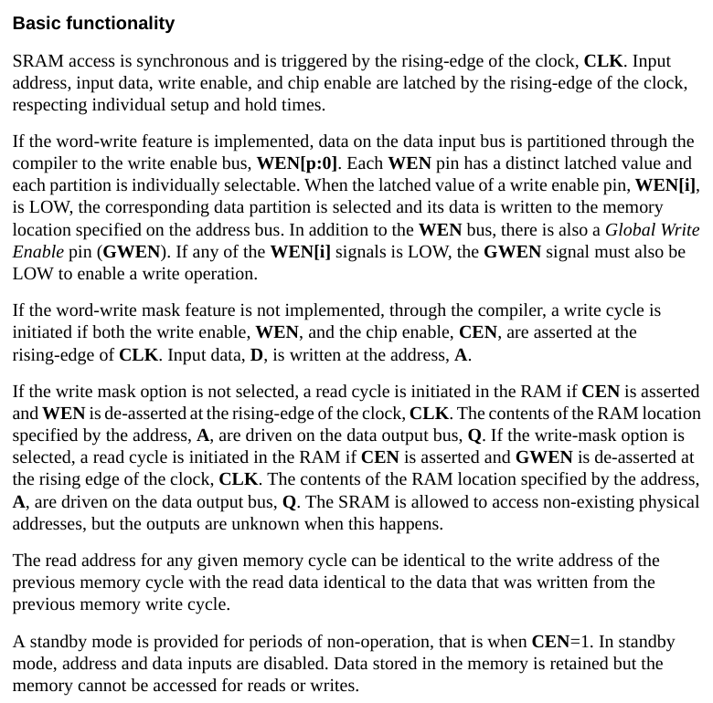
对于CLK,WEN,CEN,D,A,Q这些基本端口参考下面的描述就行。注意D,Q的位宽是和memory compiler设置里的number of bits以及multiplixer width要保持一致。而A决定了存储器深度,和memory compiler设置中的number of words之间相互换算关系是number of words = 2^A_width,即2的指数。
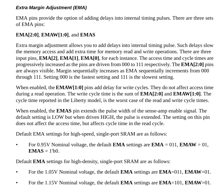
EMA口,则是用来调整信号时序margin的,只有high speed的SRAM需要用EMAS,我这里生成的SRAM是没有EMAS这个信号的,EMA[2:0]是用来减慢memory的读写操作的,增加额外的时间,EMAW[1:0]是用来写入cycle的延迟的,对于读取操作没有影响。
对于0.95V的电压来说,默认的EMA设定是EMA=011,EMAW=01。可以先用默认值,如果时序有问题就再调整。
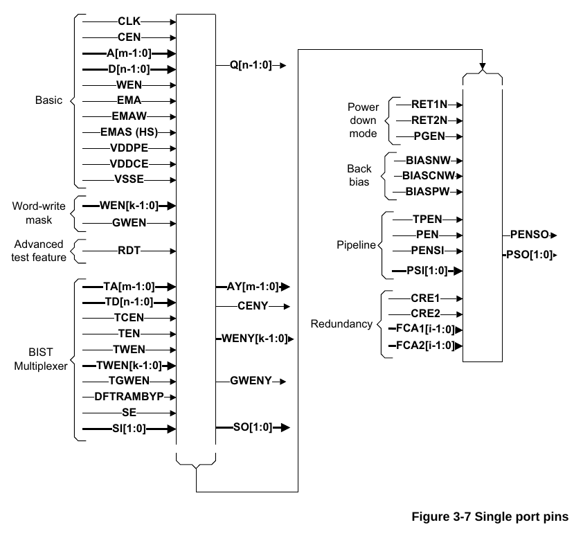
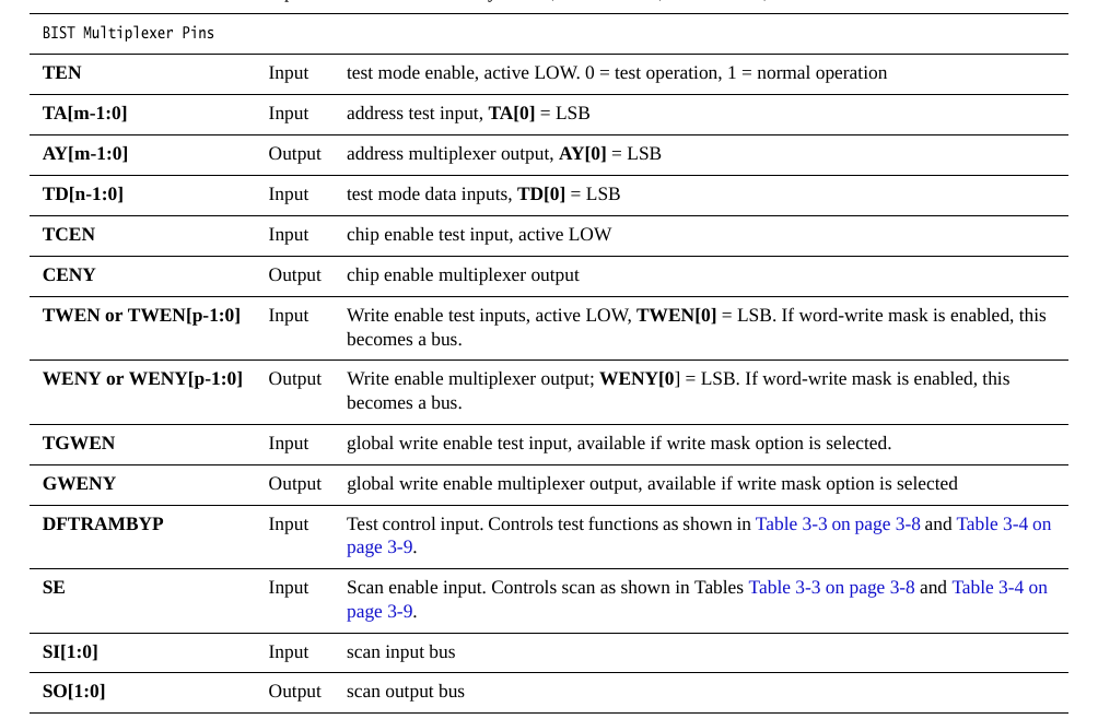
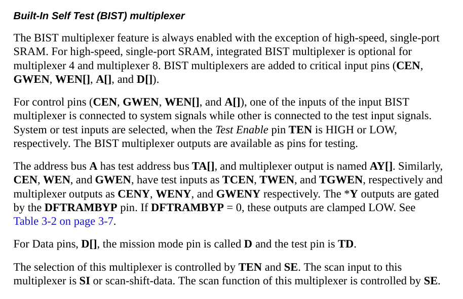
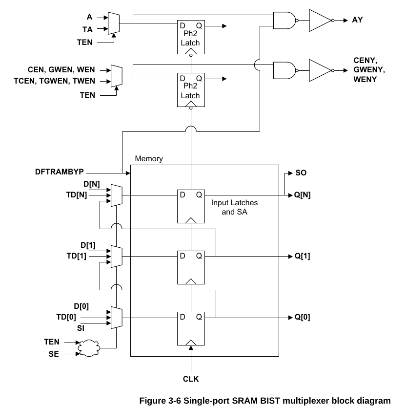
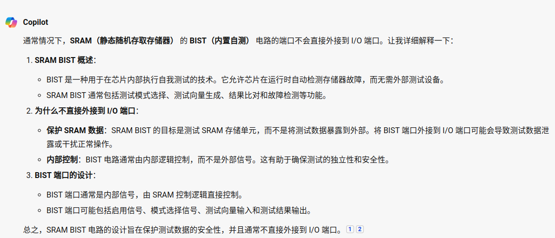
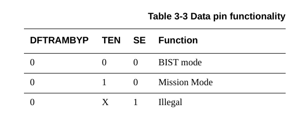
BIST(Built-In Self Test)内建测试复选器,看底下的结构图,这里就是通过TEN来选择使用普通输入还是Test输入,Test输入有TA,TD,此外还有DFTRAMBYP 和SI两个测试输入信号,而输出AY,CENY,WENY以及SO都是测试输出信号。属于一种DFT技术。
对于BIST的详细描述可以参考这篇:https://blog.csdn.net/qq_41556273/article/details/124312359
和这篇:https://www.zhihu.com/tardis/zm/art/169490809?source_id=1005
这个东西在memory compiler里默认是on的。如要使用则需要设计配合的DFT电路。
总结就是,basic信号即memory的基本读写信号,可以挂载到总线上,EMA是控制信号裕度的延迟信号,可以按照默认值来或者根据时序情况调整,BIST信号用于DFT,RET1N取决于做不做低功耗,over。
先看看gui使用:
https://blog.csdn.net/lyfwill/article/details/81330081
记住以下结论:
- 字长*字宽=行数*列数
- 行数=字长/MUX
- 列数=字宽*MUX
- MUX越大,行数越少,列数越多,micro尺寸越矮、越宽
ARM的ram compiler支持的RAM array的尺寸是有限的,最大能生成256行和320列的array(UG里面说的是Rmax=512,Cmax=576,但实际并不是这样)
那么,
MAX Number of words = MAX Number of rows * Muliplexer width = 256 * Muliplexer width
例如,Muliplexer width=4时,最大字数为256*4=1024
MAX Number of bits = MAX Number of columns / Muliplexer width = 320 / Muliplexer width
例如,Muliplexer width=8时,最大字宽为320/8=40
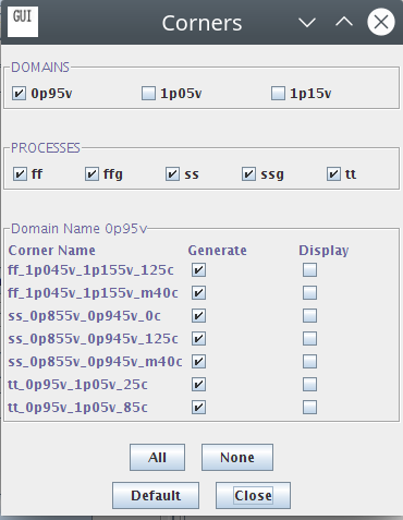
一个小点,如果不在corners里面选好电压域的话,是无法genenrate所有的view的。
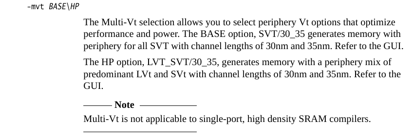
这里的电压域可以选0.95v,1.05v还有1.15v。但是需要注意的是,对于SVT/30_35模式,0.95v的corner是选不了的。然后我感觉奇怪的事情是这里手册里面说了multi-Vt is not applicable to single port high density SRAM compiler,但是我选项里面却是完全可以选的??搞不懂唉。
难道是后面又版本更新了,然后文档落后了?不管了总之先按照自己的理解用了,碰到了问题再说。just don't care about it。这里domain的命名规则是,ff/ss/tt就是fast,slow,typical,后面跟的是电压范围,如1p045v_1p155v是1.045v到1.155v,如果是我们片内使用的0.9v电压,对应的是0p855v_0p945v的ss,如果想要tt的话得要刚好0.95v。最后的xxxc指的应该是温度,比如125c指的是125度,m40c指的是零下40度。其实我们用ss三个温度的corner就够了,其他几个可以不generate。
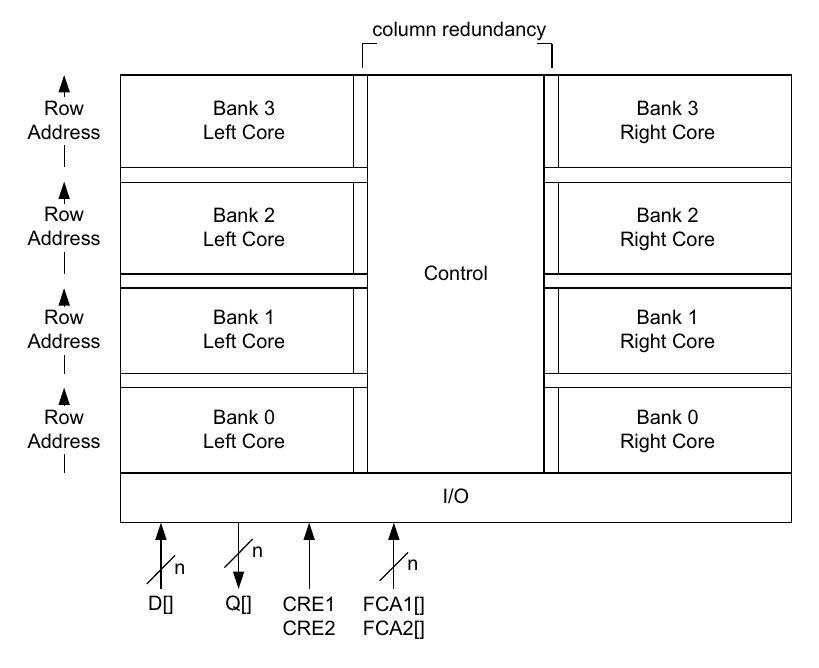
SRAM原来就是这种架构,然后重点是理解一下这个multiplixer的功能是啥:
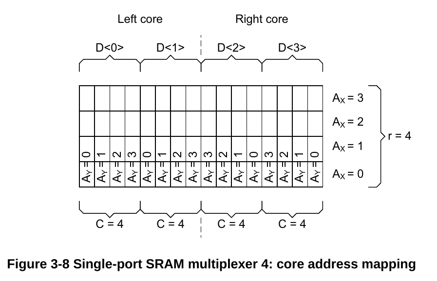
以4的case为例,multiplexer决定的是每个core bank的列数,即这里的C。我现在的主要目的是想要弄清楚,如果我想要一个32b读写宽度的端口,16b地址位宽的rom,以及一个32b读写宽度的端口,15b地址端口的ram,我该怎么设置number of words, number of bits, 以及multiplexer width这三个参数,剩下的我可以自己想着办。
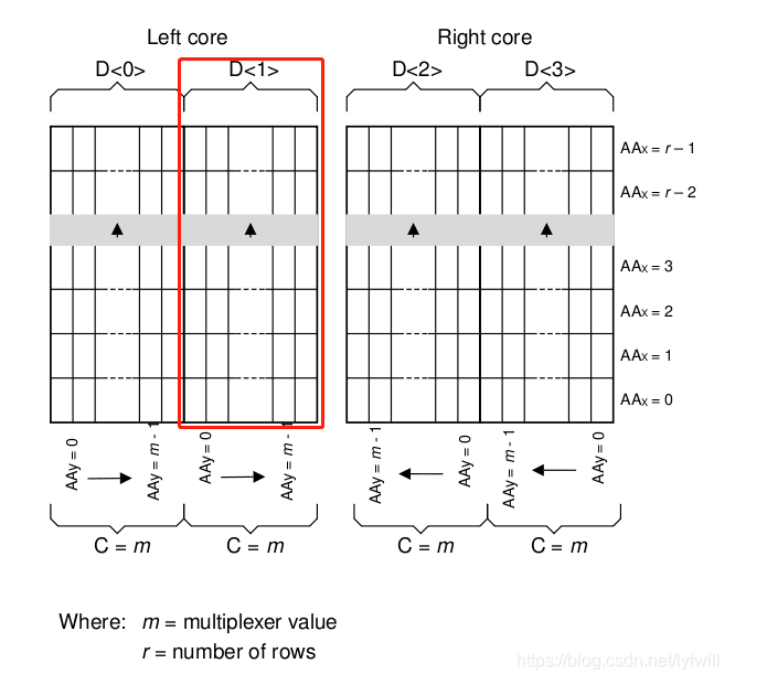
这是架构更general的情况,m由multiplexer决定这个知道了,number of rows不是可输入的参数啊........这是得自己手动推吗?
手册里面给的说明就这些.........这我怎么理解,说了等于啥都没说。
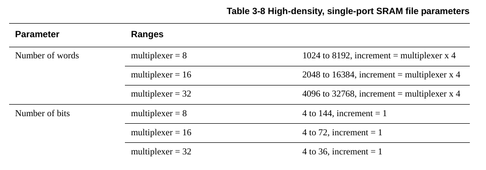
从这里理解,number of words给的就是有多少个字,每个字的字宽是多少看用户设置,看到这里说total memory bits范围是4096 to 1179648bits,那么对应的就是number of words取最小1024,number of bits取最小为4的情况,这样就是4096=1024*4。而最大则是32758*36=1179648。转换一下就是0.5KB到144KB。
然后,看一下这里的地址计算相关的问题,multiplixer=8时,mul10 to 13对应的地址数量是1024到8192,就对应了number of words。multiplixer=16和=32的时候,对应的11 to 14以及12 to 15,也是对应了上面的2048 to 16384和4096 to 32768。所以结论就是number of words直接决定了地址的位数。另外需要注意的是number of words的increment的问题,是等于multiplexer*4的,也就是multiplexer=8的时候,以32来步进,=16的时候以64步进,=32时以128步进。问题就在于这里他妈的address lines最多好像就给到15,但是我rom需要16地址啊,离谱。我想了想,主要的问题来自于如果按照8b为memory位宽的话,那确实会出现地址位不够的问题(因为上面说的要16b和15b是总线上要的地址位宽),但是如果我用之前做过的32b的方式的话,那就rom是16-2=14b,也就是16384,ram是15-2=13b,8192,就够用了。row的上限是1024,下限128;col在multiplexer=8时下限32上限1152,multiplexer=16时下限64上限1152,multiplexer=32时下限128上限1152,
根据我之前的实验,在default设置,也就是number of words=4096,number of bits=16,multiplexer width=16,最后出来的结果是:
| Port | Width | Direction | Function |
|---|---|---|---|
| CLK | 1 | input | clock |
| A | 12 | input | address (A[0]=LSB) |
| D | 16 | input | data inputs (D[0]=LSB) |
| Q | 16 | output | data outputs (Q[0]=LSB) |
| CEN | 1 | input | chip enbale, active LOW |
| WEN | 1 | input | global write enable, active LOW |
这里4096=2^12,地址就是直接和number of words有关,数据位宽是16,就是直接等于number of bits,因为试了一下改成32之后,数据Data口的位宽也变成32了。最后multiplexer width是来控制长宽比的。
好的,那么我们现在来看一下长宽比的影响的问题,根据公式以及之前的SRAM架构图可以看出multiplexer增大了列数增大,函数减小。这里的number of words就是字长,number of bits就是字宽。我们现在rom的参数是number of words=16384,number of bits=32,而ram的参数是number of words=8192,number of bits=32。我们尽量通过multiplexer使其形状不要太离谱,同时注意行列上下限,但是首先要注意的点是rom的multiplexer至少得大于8,不然地址不够用。
- 字长*字宽=行数*列数
- 行数=字长/MUX
- 列数=字宽*MUX
简单计算可知,在multiplexer=32的时候,rom的行数row=16384/32=512,而col=32*32=1024,形状1比2,col有点接近极限。multiplexer=16时,row=16384/16=1024,col=32*16=512还是1比2,但是这下row是真的直接撞到极限了..........那就还是32吧。
ram的行数在multiplexer=32时,row=8192/32=256,col=32*32=1024,为1比4,和rom的列数一样,但是行数少了一倍,如果multiplexer改成16的话,row=512,col=512,刚好1比1,裕度都不错,而且行数和rom一致,列数少了一半。
所以最后确定出来的参数是:
rom:number of words=16384,number of bits=32,multiplexer=32
ram:number of words=8192,number of bits=32,multiplexer=16
那这下就看user guide有没有骗我了。开始生成吧。
module sram_sp_hde_rom (CENY, WENY, AY, Q, SO, CLK, CEN, WEN, A, D, EMA, EMAW, TEN,
    TCEN, TWEN, TA, TD, RET1N, SI, SE, DFTRAMBYP);
`endif

  parameter ASSERT_PREFIX = "";
  parameter BITS = 32;
  parameter WORDS = 16384;
  parameter MUX = 32;
  parameter MEM_WIDTH = 1024; // redun block size 8, 512 on left, 512 on right
  parameter MEM_HEIGHT = 512;
  parameter WP_SIZE = 32 ;
  parameter UPM_WIDTH = 3;
  parameter UPMW_WIDTH = 2;
  parameter UPMS_WIDTH = 0;

  output  CENY;
  output  WENY;
  output [13:0] AY;
  output [31:0] Q;
  output [1:0] SO;
  input  CLK;
  input  CEN;
  input  WEN;
  input [13:0] A;
  input [31:0] D;
rom的代码,14位地址,32位数据,1024列数(WIDTH=col),512行数(HEIGHT=row),可以,正确。
module sram_sp_hde_ram (CENY, WENY, AY, Q, SO, CLK, CEN, WEN, A, D, EMA, EMAW, TEN,
    TCEN, TWEN, TA, TD, RET1N, SI, SE, DFTRAMBYP);
`endif

  parameter ASSERT_PREFIX = "";
  parameter BITS = 32;
  parameter WORDS = 8192;
  parameter MUX = 16;
  parameter MEM_WIDTH = 512; // redun block size 8, 256 on left, 256 on right
  parameter MEM_HEIGHT = 512;
  parameter WP_SIZE = 32 ;
  parameter UPM_WIDTH = 3;
  parameter UPMW_WIDTH = 2;
  parameter UPMS_WIDTH = 0;

  output  CENY;
  output  WENY;
  output [12:0] AY;
  output [31:0] Q;
  output [1:0] SO;
  input  CLK;
  input  CEN;
  input  WEN;
  input [12:0] A;
  input [31:0] D;
ram的代码,13位地址,32位数据,512列数(WIDTH=col),512行数(HEIGHT=row),可以,正确。
ram的lef导入virtuoso:
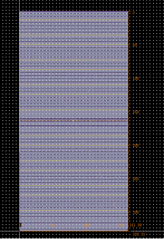
实际上反而看上去是个2比1的长条了,328*162,这次面积是2000*2000,这个不大。
rom的lef导入virtuoso:
这位更是大长条.......1比4了,168比656,可以看到长是ram的两倍........对比一下之前计算的参数,可知HEIGHT即row是短边,WIDTH即col是长边,所以我们可以知道(应该是由于左右bank的原因吧),物理长宽比例应该在上面基本计算的width/height=col/row的基础上乘个2。
行了,至此基本上都清楚了........就这样吧,想要把长宽比改的更均匀一些的话,算了一下好像要超限制。目前这两个sram的面积也不大,算一下density:
64KB/168*656(um^2)=581KB/mm^2,一平方毫米581KB,这么大?有点点怀疑我别是算错了..........
还有个问题是我没有在memory compiler里面找到GDSII的生成选项,这是在搞什么飞机?LVS Netlist也没有,很抽象。
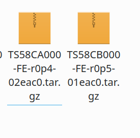
查了一下好像是要下Bank-end view的?还是要和原来的库里merge?师兄用过foundry mem,明天再问问他们吧,我觉得肯定是用得了的,不然他们之前的SRAM咋搞得。
好的,这两个压缩包,还真是FE,front-end view的,不是back-end view的。
吐出来的.lib需要转一下.db,这里用了师兄给的一个小脚本:
enable_write_lib_mode

set lib_file_list [ls *.lib]
foreach lib_file ${lib_file_list} {
 read_lib ${lib_file}
 set lib_name [get_attribute [get_libs *] name]
 set lib_file [string trim ${lib_file} ".lib"]
 write_lib ${lib_name} -o ${lib_file}.db
 remove_design -all
 }

exit
然后.lib就集体变.db了。
ok,然后接下来开始做集成。
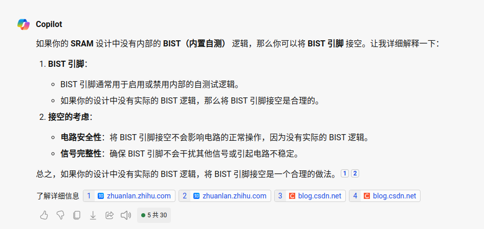
但我没写BIST逻辑,咋整,接空?不道啊。
行吧,那就接空了。
io的部分我打算还是模拟这边来进行,虽然为了进度也可以考虑数字布线,但是anyway,就划定一个core的区域,然后该怎么弄怎么弄吧。
https://www.zhihu.com/zvideo/1301656801675096064
floorplan这边还是得看一下sram出线的方向啊,但是virtuoso读进去的话看不到pin的位置和text,还是用calibre转一下?
但是现在的问题是没有找到tn28的.lef在哪,肯定是有的........
  rln = release note
  gds = GDSII layout view
  gdf = GDSII phantom view
  spi = Spice/lvs netlist
  apf = Apollo FRAM (phantom) view
  apt = Apollo FRAM and CEL (layout) view
  sef = Silicon Ensemble LEF (phantom) view
  syn = Synopsys
  vlg = Verilog simulation models
  vit = Vital (VHDL) simulaion models
  mdt = Mentor DFT (Fastscan, DFT advisor)
  doc = Documents (Data sheets)
  ibs = IBIS models
  lpe = LPE Spice netlist
  vts = Voltage strom model
  ctc = Celtic model
  sgs = Signal storm model
  pdb = Physical compiler view
  ccs = Composite Current Source (CCS) view
  nldm= Synopsys Liberty view
  vcn = Magma Volcano view
  cdk = Cadence DFII view
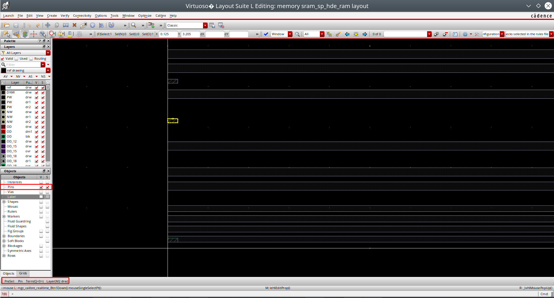
找了半天tn28的.lef未果,但是学到了另外一个看lef的pin的方法,首先是用virtuoso把lef文件导入,左下角object只选择pin就能只看到pin,然后选中,右键property,或者看左下角小标都能看到terminal name。
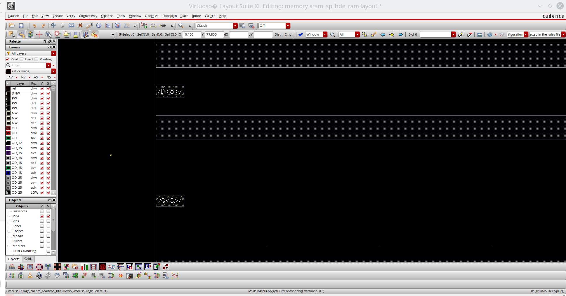
如果想要看的更清楚显示名字的话,那么可以直接开layout xl,就能直接看到名字了。
另外安排人自己做了一个techlef,也可以拿来给calibre fdi2gds来用,进行lef到gds转换,而且这样的话就直接带上label了。
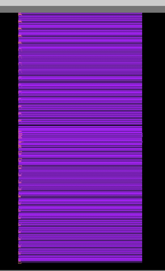
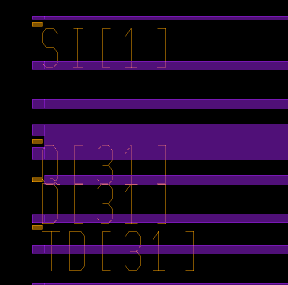
大图,可以看到sram的pin都出在了左边。所以还是把sram macro摆在芯片右端。
虽然会夹带一些乱七八糟的东西,不过无所谓了,能用就非常好了。
回到EMA和EMAW给多少这个问题上,因为我们片内电压是0.9V,所以其实这里没有一个default setting可以参考,
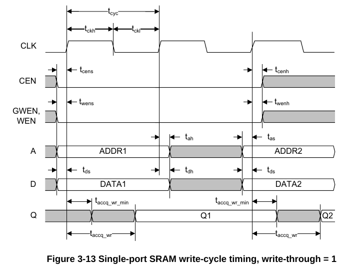
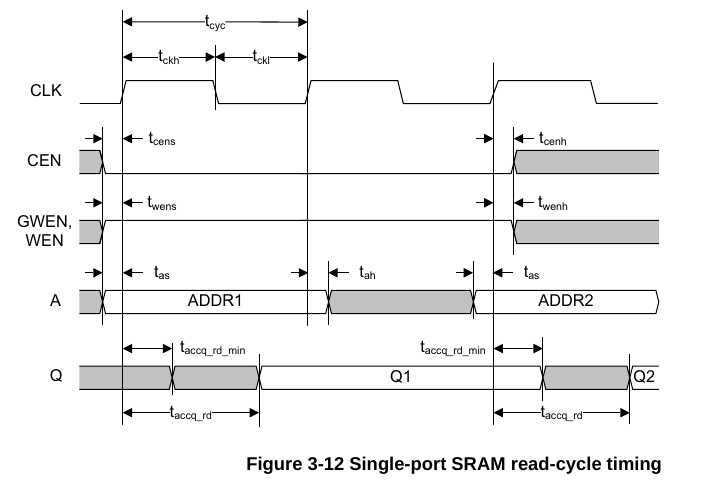
现在只知道EMA影响的是CLK->Q的延迟,EMA管的是读,EMAW管的是写,可以通过下面的时序图大概看懂,大概意思就是EMA设置的小,则delay也会变小,setup也会变大,适合更慢的应用,而倘若设置的更大,那么就是面向更快的应用。EMAW则是同理。
https://bbs.eetop.cn/thread-891674-1-1.html
才发现还有个东西叫做write-through,这个是确定写入memory的数据是否会被传播到输出端口Q上,额我觉得不能传播吧,我看看我这里的memory模型,好像都没做这个。
目前我是这样设置的:
    sram_sp_hde_ram u_sram_sp_hde_ram
    (
        .CENY(),
        .WENY(),
        .AY(),
        .Q(dout),
        .SO(),
        .CLK(clk),
        .CEN(cen),
        .WEN(wen),
        .A(addr),
        .D(din),
        .EMA(3'b011),
        .EMAW(2'b01),
        .TEN(1'b1),
        .TCEN(),
        .TWEN(),
        .TA(),
        .TD(),
        .RET1N(1'b1),
        .SI(),
        .SE(),
        .DFTRAMBYP()
    );
并不知道靠谱不靠谱。
两个问题,第一个问题,单独仿真想办法把这个sram给正常读写,第二个问题解决初始化问题,怎么把一开始readmemh到手写rom里面的二进制文件送到foundry sram的模型里面。这两个问题解决,soc整体仿真问题自然而然解决。
先从第一个开始解决吧。
要分析的代码应该是task read_write这一段:
  task readWrite;
  begin
    if (WEN_int !== 1'b1 && DFTRAMBYP_int=== 1'b0 && SE_int === 1'bx) begin
      failedWrite(0);
    end else if (DFTRAMBYP_int=== 1'b0 && SE_int === 1'b1) begin
      failedWrite(0);
        XQ = 1'b1; Q_update = 1'b1;
    end else if (RET1N_int === 1'bx || RET1N_int === 1'bz) begin
      failedWrite(0);
        XQ = 1'b1; Q_update = 1'b1;
    end else if (RET1N_int === 1'b0 && (CEN_int === 1'b0 || DFTRAMBYP_int === 1'b1)) begin
      failedWrite(0);
        XQ = 1'b1; Q_update = 1'b1;
    end else if (RET1N_int === 1'b0) begin
      // no cycle in retention mode
    end else if (^{(EMA_int & isBit1(DFTRAMBYP_int)), (EMAW_int & isBit1(DFTRAMBYP_int))} === 1'bx) begin
        XQ = 1'b1; Q_update = 1'b1;
    end else if (^{(CEN_int & !isBit1(DFTRAMBYP_int)), EMA_int, EMAW_int, RET1N_int} === 1'bx) begin
      failedWrite(0);
        XQ = 1'b1; Q_update = 1'b1;
    end else if ((A_int >= WORDS) && (CEN_int === 1'b0) && DFTRAMBYP_int === 1'b0) begin
        XQ = WEN_int !== 1'b1 ? 1'b0 : 1'b1; Q_update = WEN_int !== 1'b1 ? 1'b0 : 1'b1;
    end else if (CEN_int === 1'b0 && (^A_int) === 1'bx && DFTRAMBYP_int === 1'b0) begin
      failedWrite(0);
        XQ = 1'b1; Q_update = 1'b1;
    end else if (CEN_int === 1'b0 || DFTRAMBYP_int === 1'b1) begin
      if(isBitX(DFTRAMBYP_int) || isBitX(SE_int))
        D_int = {32{1'bx}};

      mux_address = (A_int & 4'b1111);
      row_address = (A_int >> 4);
      if (DFTRAMBYP_int !== 1'b1) begin
      if (row_address > 511)
        row = {512{1'bx}};
      else
        row = mem[row_address];
      end
      if(isBitX(DFTRAMBYP_int) || (isBitX(WEN_int) && DFTRAMBYP_int!==1)) begin
        writeEnable = {32{1'bx}};
        D_int = {32{1'bx}};
      end else
          writeEnable = ~ {32{WEN_int}};
      if (WEN_int !== 1'b1 || DFTRAMBYP_int === 1'b1 || DFTRAMBYP_int === 1'bx) begin
        row_mask =  ( {15'b000000000000000, writeEnable[31], 15'b000000000000000, writeEnable[30],
          15'b000000000000000, writeEnable[29], 15'b000000000000000, writeEnable[28],
          15'b000000000000000, writeEnable[27], 15'b000000000000000, writeEnable[26],
          15'b000000000000000, writeEnable[25], 15'b000000000000000, writeEnable[24],
          15'b000000000000000, writeEnable[23], 15'b000000000000000, writeEnable[22],
          15'b000000000000000, writeEnable[21], 15'b000000000000000, writeEnable[20],
          15'b000000000000000, writeEnable[19], 15'b000000000000000, writeEnable[18],
          15'b000000000000000, writeEnable[17], 15'b000000000000000, writeEnable[16],
          15'b000000000000000, writeEnable[15], 15'b000000000000000, writeEnable[14],
          15'b000000000000000, writeEnable[13], 15'b000000000000000, writeEnable[12],
          15'b000000000000000, writeEnable[11], 15'b000000000000000, writeEnable[10],
          15'b000000000000000, writeEnable[9], 15'b000000000000000, writeEnable[8],
          15'b000000000000000, writeEnable[7], 15'b000000000000000, writeEnable[6],
          15'b000000000000000, writeEnable[5], 15'b000000000000000, writeEnable[4],
          15'b000000000000000, writeEnable[3], 15'b000000000000000, writeEnable[2],
          15'b000000000000000, writeEnable[1], 15'b000000000000000, writeEnable[0]} << mux_address);
        new_data =  ( {15'b000000000000000, D_int[31], 15'b000000000000000, D_int[30],
          15'b000000000000000, D_int[29], 15'b000000000000000, D_int[28], 15'b000000000000000, D_int[27],
          15'b000000000000000, D_int[26], 15'b000000000000000, D_int[25], 15'b000000000000000, D_int[24],
          15'b000000000000000, D_int[23], 15'b000000000000000, D_int[22], 15'b000000000000000, D_int[21],
          15'b000000000000000, D_int[20], 15'b000000000000000, D_int[19], 15'b000000000000000, D_int[18],
          15'b000000000000000, D_int[17], 15'b000000000000000, D_int[16], 15'b000000000000000, D_int[15],
          15'b000000000000000, D_int[14], 15'b000000000000000, D_int[13], 15'b000000000000000, D_int[12],
          15'b000000000000000, D_int[11], 15'b000000000000000, D_int[10], 15'b000000000000000, D_int[9],
          15'b000000000000000, D_int[8], 15'b000000000000000, D_int[7], 15'b000000000000000, D_int[6],
          15'b000000000000000, D_int[5], 15'b000000000000000, D_int[4], 15'b000000000000000, D_int[3],
          15'b000000000000000, D_int[2], 15'b000000000000000, D_int[1], 15'b000000000000000, D_int[0]} << mux_address);
        row = (row & ~row_mask) | (row_mask & (~row_mask | new_data));
        if (DFTRAMBYP_int === 1'b1 && SE_int === 1'b0) begin
        end else if (WEN_int !== 1'b1 && DFTRAMBYP_int === 1'b1 && SE_int === 1'bx) begin
        	XQ = 1'b1; Q_update = 1'b1;
        end else begin
        mem[row_address] = row;
        end
      end else begin
        data_out = (row >> (mux_address%8));
        readLatch0 = {data_out[504], data_out[496], data_out[488], data_out[480], data_out[472],
          data_out[464], data_out[456], data_out[448], data_out[440], data_out[432],
          data_out[424], data_out[416], data_out[408], data_out[400], data_out[392],
          data_out[384], data_out[376], data_out[368], data_out[360], data_out[352],
          data_out[344], data_out[336], data_out[328], data_out[320], data_out[312],
          data_out[304], data_out[296], data_out[288], data_out[280], data_out[272],
          data_out[264], data_out[256], data_out[248], data_out[240], data_out[232],
          data_out[224], data_out[216], data_out[208], data_out[200], data_out[192],
          data_out[184], data_out[176], data_out[168], data_out[160], data_out[152],
          data_out[144], data_out[136], data_out[128], data_out[120], data_out[112],
          data_out[104], data_out[96], data_out[88], data_out[80], data_out[72], data_out[64],
          data_out[56], data_out[48], data_out[40], data_out[32], data_out[24], data_out[16],
          data_out[8], data_out[0]};
        shifted_readLatch0 = (readLatch0 >> A_int[3]);
        mem_path = {shifted_readLatch0[62], shifted_readLatch0[60], shifted_readLatch0[58],
          shifted_readLatch0[56], shifted_readLatch0[54], shifted_readLatch0[52], shifted_readLatch0[50],
          shifted_readLatch0[48], shifted_readLatch0[46], shifted_readLatch0[44], shifted_readLatch0[42],
          shifted_readLatch0[40], shifted_readLatch0[38], shifted_readLatch0[36], shifted_readLatch0[34],
          shifted_readLatch0[32], shifted_readLatch0[30], shifted_readLatch0[28], shifted_readLatch0[26],
          shifted_readLatch0[24], shifted_readLatch0[22], shifted_readLatch0[20], shifted_readLatch0[18],
          shifted_readLatch0[16], shifted_readLatch0[14], shifted_readLatch0[12], shifted_readLatch0[10],
          shifted_readLatch0[8], shifted_readLatch0[6], shifted_readLatch0[4], shifted_readLatch0[2],
          shifted_readLatch0[0]};
        	XQ = 1'b0; Q_update = 1'b1;
      end
      if (DFTRAMBYP_int === 1'b1) begin
        	XQ = 1'b0; Q_update = 1'b1;
      end
      if( isBitX(WEN_int) && DFTRAMBYP_int !== 1'b1) begin
        XQ = 1'b1; Q_update = 1'b1;
      end
      if( isBitX(DFTRAMBYP_int) ) begin
        XQ = 1'b1; Q_update = 1'b1;
      end
      if( isBitX(SE_int) && DFTRAMBYP_int === 1'b1 ) begin
        XQ = 1'b1; Q_update = 1'b1;
      end
    end
  end
  endtask
现在仿真碰到的问题是,读写的操作好像都没有成功。
乱试了一通统统给0,不知道是哪个试对了,这些突然可以成功读写了,逆天。
ok,实验成功,就是SE得要给0,那就是上面这个表,DFTRAMBYP给0,TEN给1,SE给0,就是正常工作模式。搞定,记录一下仿真正常的波形,那么问题1解决,就只有问题2了。
加了个+define+INITIALIZE_MEMORY的宏定义,全部初始化成0,这样方便观察,不然看到的全是xxxx。
好的,现在我们想要试着往这个mem里面直接写数据,碰到的问题是:
Error-[XMRE] Cross-module reference resolution error
../../tb/tb_tinyriscv_soc.v, 34
  Error found while trying to resolve cross-module reference.
  token 'mem'.  Originating module 'tb_tinyriscv_soc'.
  Source info: $readmemh("../../../../sw/project/build/rvcim.data",
  tinyriscv_soc_top_0.u_rom.mem);
归根结底就是这个$readmemh的方式直接往mem里面直接写的方式没成功........好吧这里的问题就是索引错了。
$readmemh ("../../../../sw/project/build/rvcim.data", tinyriscv_soc_top_0.u_rom.u_sp_rom_wrapper.u_sram_sp_hde_rom.mem);
这样编译就过了。
但是还有一个点是,应该不能够采用直接这样往那个mem里面赋值的方式,因为那玩意它不是一个顺序分布的。看上面的仿真里面memory界面就知道了,直接顺序加载那肯定直接爆炸。
那么怎么办呢?两个思路,第一个是把这个.data进行一波转换,转换到符合mem内容的格式,但是这里的问题是实际上不知道他里面的memory mapping是个什么原理,压根不懂。思路二,写一个task,先把数据给readmemh到一个标准mem里面,然后再让它去写入到mem里面去。
都可以,最后没用arm的这个memory compiler了,用了TSMC的MC2,有时间再说那个的使用。反正arm这个的至少到仿真的流程是跑通了,综合啥的都是自然而然的事情了。














【推荐】国内首个AI IDE,深度理解中文开发场景,立即下载体验Trae
【推荐】编程新体验,更懂你的AI,立即体验豆包MarsCode编程助手
【推荐】抖音旗下AI助手豆包,你的智能百科全书,全免费不限次数
【推荐】轻量又高性能的 SSH 工具 IShell:AI 加持,快人一步
· 阿里最新开源QwQ-32B,效果媲美deepseek-r1满血版,部署成本又又又降低了!
· 开源Multi-agent AI智能体框架aevatar.ai,欢迎大家贡献代码
· Manus重磅发布:全球首款通用AI代理技术深度解析与实战指南
· 被坑几百块钱后,我竟然真的恢复了删除的微信聊天记录!
· AI技术革命,工作效率10个最佳AI工具