第十章:形状
第十章:形状
形状
目前为止,我们已经使用过矩形Rectangle元素和控件,但还未用过不规则形状,这只能依赖图片。使用Qt Quick形状模块可以创建不规则形状。这使得直接从QML中灵活地创建可视元素成为可能。
本章我们将研究如何使用形状、各种可用的路径元素,如何以不同方式填充形状,以及形状如何结合QML的强大能力来形成流畅的动画的形状。
一个简单形状
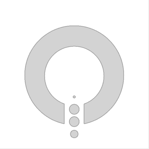
形状模块可让您创建任意路径,然后描边轮廓并填充内部。路径的定义可以在其它使用路径的地方重用,比如,用于模型的PathView元素。但对于路径的绘制,要用到Shape元素,且各种路径元素被放到了ShapePath。
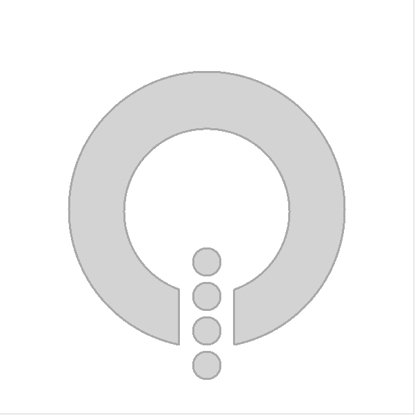
在下面的例子中,创建了这个抓屏所显示的路径。整个图象,五块填充区域,都是从一条路径创建然后被描边和填充的。
import QtQuick
import QtQuick.Shapes

Rectangle {
    id: root
    width: 600
    height: 600

    Shape {
        anchors.centerIn: parent

        ShapePath {

            strokeWidth: 3
            strokeColor: "darkGray"
            fillColor: "lightGray"

            startX: -40; startY: 200

            // The circle

            PathArc { x: 40; y: 200; radiusX: 200; radiusY: 200; useLargeArc: true }
            PathLine { x: 40; y: 120 }
            PathArc { x: -40; y: 120; radiusX: 120; radiusY: 120; useLargeArc: true; direction: PathArc.Counterclockwise }
            PathLine { x: -40; y: 200 }

            // The dots

            PathMove { x: -20; y: 80 }
            PathArc { x: 20; y: 80; radiusX: 20; radiusY: 20; useLargeArc: true }
            PathArc { x: -20; y: 80; radiusX: 20; radiusY: 20; useLargeArc: true }

            PathMove { x: -20; y: 130 }
            PathArc { x: 20; y: 130; radiusX: 20; radiusY: 20; useLargeArc: true }
            PathArc { x: -20; y: 130; radiusX: 20; radiusY: 20; useLargeArc: true }

            PathMove { x: -20; y: 180 }
            PathArc { x: 20; y: 180; radiusX: 20; radiusY: 20; useLargeArc: true }
            PathArc { x: -20; y: 180; radiusX: 20; radiusY: 20; useLargeArc: true }

            PathMove { x: -20; y: 230 }
            PathArc { x: 20; y: 230; radiusX: 20; radiusY: 20; useLargeArc: true }
            PathArc { x: -20; y: 230; radiusX: 20; radiusY: 20; useLargeArc: true }
        }
    }
}路径是由ShapePath的子元素组成的,比如,上例中的PathArc,PathLine和PathMove元素。下一节中,我们将仔细观察路径的构建部分。
创建路径
正如在上一节看到的,形状是由多个路径构建的,即由一些路径元素来构建。最通用的构建路径的方式是闭合它,比如,确保开始及终止结点在同一位置。虽然可以创建非闭合路径,比如,仅描画线时。当填充非闭合路径时,路径是通过在直线上添加填充路径所用的PathLine来关闭的,而非通过描边。
如下面截图所示,一些基本的形状有助于构建复杂路径。它们是:线,弧线和各种曲线。也可以使用PathMove元素仅移动不画线。除了这些元素外,ShapePath元素也允许使用startX和startY属性来指定起始点。
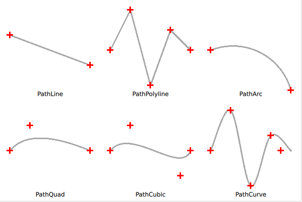
如下所示,线是通过PathLine元素来绘制的。想绘制多条独立的线段,可以使用PathMultiline。
Shape {
    ShapePath {
        strokeWidth: 3
        strokeColor: "darkgray"

        startX: 20; startY: 70

        PathLine {
            x: 180
            y: 130
        }
    }
}当创建折线,比如,由多条线段组成的线,可以使用PathPolyline元素。这样可以少输入些代码,因为上一条线段的终点被设置为下一条线段的起点。
Shape {
    ShapePath {
        strokeWidth: 3
        strokeColor: "darkgray"

        PathPolyline {
            path: [
                Qt.point(220, 100),
                Qt.point(260, 20),
                Qt.point(300, 170),
                Qt.point(340, 60),
                Qt.point(380, 100)
            ]
        }
    }
}创建弧线,比如圆形或椭圆形上的一段线,可以使用PathArc和PathAngleArc元素。它们提供了创建弧线的工具,当已知起始点与终止点时,使用PathArc;当想要控制弧扫过的度数时,PathAngleArc 很有用。两个元素都有同样的效果,用哪一个,取决于对程序来讲更看重哪个方面。
Shape {
    ShapePath {
        strokeWidth: 3
        strokeColor: "darkgray"

        startX: 420; startY: 100

        PathArc {
            x: 580; y: 180
            radiusX: 120; radiusY: 120
        }
    }
}
线与弧后紧接着的是各种曲线。这里,Qt Quick形状模块提供了三种风格。首先,一起来看下PathQuad,允许根据起点和终点(起点是隐含的)和单个控制点创建二次贝塞尔曲线。
Shape {
    ShapePath {
        strokeWidth: 3
        strokeColor: "darkgray"

        startX: 20; startY: 300

        PathQuad {
            x: 180; y: 300
            controlX: 60; controlY: 250
        }
    }
}
PathCubic 元素从起点和终点(起点是隐含的)和两个控制点创建一条三次贝塞尔曲线。
Shape {
    ShapePath {
        strokeWidth: 3
        strokeColor: "darkgray"

        startX: 220; startY: 300

        PathCubic {
            x: 380; y: 300
            control1X: 260; control1Y: 250
            control2X: 360; control2Y: 350
        }
    }
}最后,PathCurve 创建一条通过所定义的控制点列表的曲线。曲线是通过提供多个 PathCurve 元素创建的,每个元素都包含一个控制点。 Catmull-Rom 样条用于创建通过控制点的曲线。
Shape {
    ShapePath {
        strokeWidth: 3
        strokeColor: "darkgray"

        startX: 420; startY: 300

        PathCurve { x: 460; y: 220 }
        PathCurve { x: 500; y: 370 }
        PathCurve { x: 540; y: 270 }
        PathCurve { x: 580; y: 300 }
    }
}
还有一个更有用的路径元素 PathSvg。此元素可描边和填充 SVG 路径。
注意
PathSvg元素不能总是与其他路径元素组合。这取决于采用的后端绘制方法,所以,请单独在一个路径里使用PathSvg或其它元素。如果将PathSvg或其它路径元素混用,效果可能跟你期待的不一样。
填充形状
图形可以以不同方式进行填充。本节将讲到通常的填充规则,以及各种不同的填充方式。
Qt Quick 形状模块使用ShapePath元素的fillRule属性提供了两种填充控制规则。下面的截图显示了两种不同的效果。它可以被设置成默认的ShapePath.OddEvenFill(奇偶填充)。这将逐一填充路径的每个部分,也就是可以创建有洞的形状。另一条规则是ShapePath.WindingFill,填充形状上每条水平线的端点之间的所有内容。不管填充规则如何,接下来要使用笔绘制形状轮廓,因此即使使用缠绕填充规则,轮廓也会在形状内部绘制。
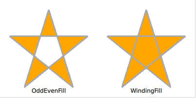
下面的例子演示了如何使用上图所示效果的不同的填充方式。
Shape {
    ShapePath {
        strokeWidth: 3
        strokeColor: "darkgray"
        fillColor: "orange"

        fillRule: ShapePath.OddEvenFill

        PathPolyline {
            path: [
                Qt.point(100,  20),
                Qt.point(150, 180),
                Qt.point( 20,  75),
                Qt.point(180,  75),
                Qt.point( 50, 180),
                Qt.point(100,  20),
            ]
        }
    }
}
Shape {
ShapePath {
strokeWidth: 3
strokeColor: "darkgray"
fillColor: "orange"
fillRule: ShapePath.WindingFill
PathPolyline {
path: [
Qt.point(300, 20),
Qt.point(350, 180),
Qt.point(220, 75),
Qt.point(380, 75),
Qt.point(250, 180),
Qt.point(300, 20),
]
}
}
}一旦确定了填充规则,有多种方法可以填充轮廓。各种方法实现的效果如下截图所示。这些方法或是纯色,或是Qt Quick提供的三种渐变之一。
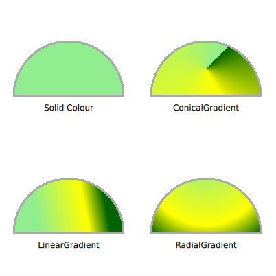
使用纯色来填充形状,要用到ShapePath的fillColor属性。将其设置为颜色的名称或颜色代码,形状就会被其填充。
Shape {
    ShapePath {
        strokeWidth: 3
        strokeColor: "darkgray"

        fillColor: "lightgreen"

        startX: 20; startY: 140

        PathLine {
            x: 180
            y: 140
        }
        PathArc {
            x: 20
            y: 140
            radiusX: 80
            radiusY: 80
            direction: PathArc.Counterclockwise
            useLargeArc: true
        }
    }
}如果不想用纯色,可以使用渐变。渐变是通过ShapePath元素的fillGradient属性来应用的。
首先来看线性渐变LinearGradient。其在起点与终点间创建了一个线性渐变。终点(渐变节点)可以在任意方式创建,比如,一定角度的渐变。在这些(渐变)节点之间,可以插入一系列GradientStop元素。它们被放在position里,从0.0,在x1,y1坐标位置,到1.0,在x2,y2坐标位置。对于每一个节点,要指定一个颜色。渐变会在这些节点颜色间创建过渡。
注意
如果形状超过最后的渐变节点,则首个或开个节点颜色将被继续延用,或将渐变重复或镜象。这是能过LinearGradient元素的spread属性来指定的。
Shape {
    ShapePath {
        strokeWidth: 3
        strokeColor: "darkgray"

        fillGradient: LinearGradient {
            x1: 50; y1: 300
            x2: 150; y2: 280

            GradientStop { position: 0.0; color: "lightgreen" }
            GradientStop { position: 0.7; color: "yellow" }
            GradientStop { position: 1.0; color: "darkgreen" }
        }

        startX: 20; startY: 340

        PathLine {
            x: 180
            y: 340
        }
        PathArc {
            x: 20
            y: 340
            radiusX: 80
            radiusY: 80
            direction: PathArc.Counterclockwise
            useLargeArc: true
        }
    }
}要创建一个围绕原点传播的渐变,有点像时钟那样,要使用ConicalGradient。这时,要通过centerX和centerY属性来指定中间节点,通过angle给出开始角度。渐变从给定的角度开始沿顺时针方向做360度展开。
Shape {
    ShapePath {
        strokeWidth: 3
        strokeColor: "darkgray"

        fillGradient: ConicalGradient {
            centerX: 300; centerY: 100
            angle: 45

            GradientStop { position: 0.0; color: "lightgreen" }
            GradientStop { position: 0.7; color: "yellow" }
            GradientStop { position: 1.0; color: "darkgreen" }
        }

        startX: 220; startY: 140

        PathLine {
            x: 380
            y: 140
        }
        PathArc {
            x: 220
            y: 140
            radiusX: 80
            radiusY: 80
            direction: PathArc.Counterclockwise
            useLargeArc: true
        }
    }
}
为了创建一个形成圆形的渐变,有点像水面上的环,使用了 RadialGradient。这需要指定两个圆,焦点圆和中心圆。渐变从焦点圆向中心圆扩展,越过这些圆后,最末节点的颜色会继续,被镜象或重复,依赖于spread属性。
Shape {
    ShapePath {
        strokeWidth: 3
        strokeColor: "darkgray"

        fillGradient: RadialGradient {
            centerX: 300; centerY: 250; centerRadius: 120
            focalX: 300; focalY: 220; focalRadius: 10

            GradientStop { position: 0.0; color: "lightgreen" }
            GradientStop { position: 0.7; color: "yellow" }
            GradientStop { position: 1.0; color: "darkgreen" }
        }

        startX: 220; startY: 340

        PathLine {
            x: 380
            y: 340
        }
        PathArc {
            x: 220
            y: 340
            radiusX: 80
            radiusY: 80
            direction: PathArc.Counterclockwise
            useLargeArc: true
        }
    }
}
注意
高级用户可以使用片段着色器来填充形状。这样,您就可以完全自由地选择形状的填充方式。有关着色器的更多信息,请参阅效果章节。
形状动画
Qt Quick形状模块用法的妙处之一,就是可以在QML中直接完成路径绘制。这意味着它们的属性可以被绑定、实现过渡、动画效果,就象QML中其它的属性那样。
下面的例子中,我们将再次用到本章第一节里用到的形状,但将引入新的变量,t,并在从0.0到1.0的循环中做成动画效果。使用这个变量来偏移小圆形的位置,以及最项部和最底部圆形的大小。这将创建一个动画,看起来象圆圈出现在顶部并朝底部消失。
import QtQuick
import QtQuick.Shapes

Rectangle {
    id: root
    width: 600
    height: 600

    Shape {
        anchors.centerIn: parent

        ShapePath {
            id: shapepath

            property real t: 0.0

            NumberAnimation on t { from: 0.0; to: 1.0; duration: 500; loops: Animation.Infinite; running: true }

            strokeWidth: 3
            strokeColor: "darkGray"
            fillColor: "lightGray"

            startX: -40; startY: 200

            // The circle

            PathArc { x: 40; y: 200; radiusX: 200; radiusY: 200; useLargeArc: true }
            PathLine { x: 40; y: 120 }
            PathArc { x: -40; y: 120; radiusX: 120; radiusY: 120; useLargeArc: true; direction: PathArc.Counterclockwise }
            PathLine { x: -40; y: 200 }

            // The dots

            PathMove { x: -20+(1.0-shapepath.t)*20; y: 80 + shapepath.t*50 }
            PathArc { x: 20-(1.0-shapepath.t)*20; y: 80 + shapepath.t*50; radiusX: 20*shapepath.t; radiusY: 20*shapepath.t; useLargeArc: true }
            PathArc { x: -20+(1.0-shapepath.t)*20; y: 80 + shapepath.t*50; radiusX: 20*shapepath.t; radiusY: 20*shapepath.t; useLargeArc: true }

            PathMove { x: -20; y: 130 + shapepath.t*50 }
            PathArc { x: 20; y: 130 + shapepath.t*50; radiusX: 20; radiusY: 20; useLargeArc: true }
            PathArc { x: -20; y: 130 + shapepath.t*50; radiusX: 20; radiusY: 20; useLargeArc: true }

            PathMove { x: -20; y: 180 + shapepath.t*50 }
            PathArc { x: 20; y: 180 + shapepath.t*50; radiusX: 20; radiusY: 20; useLargeArc: true }
            PathArc { x: -20; y: 180 + shapepath.t*50; radiusX: 20; radiusY: 20; useLargeArc: true }

            PathMove { x: -20+shapepath.t*20; y: 230 + shapepath.t*50 }
            PathArc { x: 20-shapepath.t*20; y: 230 + shapepath.t*50; radiusX: 20*(1.0-shapepath.t); radiusY: 20*(1.0-shapepath.t); useLargeArc: true }
            PathArc { x: -20+shapepath.t*20; y: 230 + shapepath.t*50; radiusX: 20*(1.0-shapepath.t); radiusY: 20*(1.0-shapepath.t); useLargeArc: true }
        }
    }
}注意NumberAnimation on t的用法,可以绑定其它任何属性,比如,绑到滑块、或外部状态等。只有你想不到,没有做不到。
总结
本章里我们了解到Qt Quick形状模块能提供什么功能。使用它可以在QML创建任意形状,并通过QML系统所带有的property创建动态形状。我们也了解了可用于创建形状的各种路径段,如线、弧,以及各种曲线。最后,我们探索了填充选项,可用于为已有路径创建令人振奋的视觉效果。

 浙公网安备 33010602011771号