HDLBits-Verilog Practice-2-Circuits.Sequential Logic -> Circuits.More Circuits
注:建议使用 Ctrl+F 利用关键词、题号、题目名称 查阅本文内容
笔记内容
-
本文范围 Circuits.Sequential Logic -> Circuits.More Circuits
-
网页本身给出的语法点,和一些语法的使用思路
-
做题过程中的反思
-
参考答案xiaop1/Verilog-Practice: HDLBits website practices & solutions
Circuits
Sequential Logic
Latches and Flip-Flops
笔记
T81,Dff
-
A D flip-flop is a circuit that stores a bit and is updated periodically, at the (usually) positive edge of a clock signal.
-
D flip-flops are created by the logic synthesizer when a clocked always block is used (See alwaysblock2).
-
A D flip-flop is the simplest form of "blob of combinational logic followed by a flip-flop" where the combinational logic portion is just a wire.

T83,DFF with reset
题干:Create 8 D flip-flops with active high synchronous reset. All DFFs should be triggered by the positive edge of clk.
生词:
- active high: An active high device is a device that either outputs a HIGH signal when triggered on or that accepts a high signal as input to turn on. It really depends on whether the device is an input or an output device.
- synchronous reset: Synchronous resets are based on the premise that the reset signal will only affect or reset the state of the flip-flop on the active edge of a clock. The reset can be applied to the flip-flop as part of the combinational logic generating the d-input to the flip-flop.
- 同步逻辑:整个设计中只有一个全局时钟成为同步逻辑。只有时钟脉冲同时到达各记忆元件的时钟端,才能发生预期改变。
- 同步逻辑是时钟之间有固定的因果关系。
- 同步时序逻辑电路的特点:各触发器的时钟端全部连接在一起,并接在系统时钟端,只有当时钟脉冲到来时,电路的状态才能改变。改变后的状态将一直保持到下一个时钟脉冲的到来,此时无论外部输入 x 有无变化,状态表中的每个状态都是稳定的。
- 异步逻辑:多时钟系统逻辑设计成为异步逻辑。电路状态改变由输入信号引起。
- 异步逻辑是各时钟之间没有固定的因果关系。
- 异步时序逻辑电路的特点:电路中除可以使用带时钟的触发器外,还可以使用不带时钟的触发器和延迟元件作为存储元件,电路中没有统一的时钟,电路状态的改变由外部输入的变化直接引起。
- 锁存器就是不带时钟的触发器
T87,Exams/m2014 q4a (D-latch)

这题为设计一个锁存器。
- 锁存器是 电平敏感的(level-sensitive)而非 边沿敏感的(edge-sensitive) 电路,所以在过程块中使用电平敏感的敏感列表。
- 但锁存器仍旧是个时序的组件,因此在过程块中将使用 非阻塞赋值。
- D-latch 在使能信号为1时,功能为一个导线,或者 为一个 non-inverting buffer;使能信号为0时保存现有值不变。
T85,DFF with asynchronous reset
异步复位呆码和同步复位呆码的差别体现在 sensitivity list 上。
以下为本题,两种复位方式的呆码和对应时序图。
同步复位
module top_module (
    input clk,
    input areset,   // active high asynchronous reset
    input [7:0] d,
    output [7:0] q
);
    always@(posedge clk)begin
        if(areset)
            q<=8'h00;
        else
            q<=d;
    end
endmodule
异步复位
module top_module (
    input clk,
    input areset,   // active high asynchronous reset
    input [7:0] d,
    output [7:0] q
);
    always@(posedge clk,posedge areset)begin
        if(areset)
            q<=8'h00;
        else
            q<=d;
    end
endmodule
图中,yours 为同步复位的时序图,ref 为异步复位的时序图。
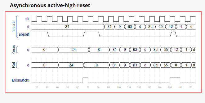
仔细想一下,我们需要的异步复位是 areset 电平为1时 复位,那么为什么在敏感列表里添上的是 areset ↑ 触发 过程块?为什么这么做有用?
只需要穷举一下所有的情况分析就好啦。如下表所示。
In Verilog, the sensitivity list looks strange. The FF's reset is sensitive to the level of areset, so why does using "posedge areset" work?
To see why it works, consider the truth table for all events that change the input signals, assuming clk and areset do not switch at precisely the same time:
| clk | areset | output | |
|---|---|---|---|
| x | 0->1 | q<=0 | because areset=1 |
| x | 1->0 | no change | always block not triggered |
| 0->1 | 0 | q<=0 | not resetting |
| 0->1 | 1 | q<=0 | still resetting as q was 0 before too! |
| 1->0 | x | no change | always block not triggered |
注:我们假设一个工作时钟为 1Hz 的系统,比如你的床头闹钟,你按下隆隆叫的闹钟时,就好比按下了闹钟的同步复位键。那么当你清晨 6:30:00 的闹钟响起,不想起床的你拍下闹钟,最糟糕的情况下,闹钟还会再响接近一秒,因为你刚好错过了一个时钟上升沿,真是糟糕,这真是太可怕了!
对于同步复位系统来说,当同步复位事件发生时,等到下一个时钟上升沿才会得到响应,响应的速度比较慢。
与之相对的异步复位的响应就很快,因为在异步复位有效的时刻,复位响应就会发生,好像戳破气球一般。
作者:LogicJitterGibbs
链接:https://zhuanlan.zhihu.com/p/61225914
来源:知乎
著作权归作者所有。商业转载请联系作者获得授权,非商业转载请注明出处。
T86,Dff16e
有时候仅需要根据使能信号修改一组触发器的部分值。
注:1. 个人觉得这里用 case写分支 比用 if-else语句 更为清晰。2. 使能信号 byteena不应放进敏感列表!!!(放进去就变成了奇怪的异步逻辑了)
module top_module (
    input clk,
    input resetn,
    input [1:0] byteena,
    input [15:0] d,
    output [15:0] q
);
    always@(posedge clk)begin
        if(~resetn)
            q<={$bits(q){1'b0}};
        else begin
            case(byteena)
                2'b01: q[7:0]<=d[7:0];
                2'b10: q[15:8]<=d[15:8];
                2'b11: q<=d;
                2'b00: q<=q;
            endcase
        end
    end

endmodule
好吧,评论区里看到了一个更简洁的写法
always @(posedge clk) begin
    if (~resetn)
		q <= 0;
	else
		q <= {(byteena[1] ? d[15:8] : q[15:8]), (byteena[0] ? d[7:0] : q[7:0])};
end
还有一个建议将组合逻辑与时序逻辑分开的写法
wire [15:0]q_temp;
reg [15:0]q_reg;

assign q_temp[15-:8] = byteena[1]?d[15-:8]:q_reg[15-:8];
assign q_temp[7-:8] = byteena[0]?d[7-:8]:q_reg[7-:8];

always@(posedge clk)
	if(resetn == 1'b0)
		q_reg <= 16'h0;
	else
q_reg <= q_temp;

assign q = q_reg;
T93,Ece241_2014_q4
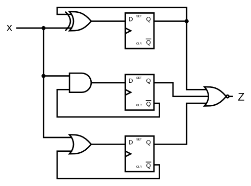
题目给的电路图中忘记给三个触发器接clk了。但是显然是需要的,这里触发器起到缓存的功能,如果不通过缓存降低输出更新的频率话,仿真时会报错# ** Error (suppressible): (vsim-3601) Iteration limit 5000 reached at time 85 ps.;想来这样的电路上板子应该也不稳定。
-
我采用模块化的实现方式,解答如下,
module top_module (
    input clk,
    input x,
    output z
);
    reg [2:0]Q,Qbar,D;

    myDff i1 (clk,x^Q[0],Q[0],Qbar[0]);
    myDff i2 (clk,x&Qbar[1],Q[1],Qbar[1]);
    myDff i3 (clk,x|Qbar[2],Q[2],Qbar[2]);

    assign	z=~(Q[0]|Q[1]|Q[2]);
endmodule

module myDff(
    input clk,
    input D,
    output reg Q,
    output reg Qbar);

    always@(posedge clk)
        Q<=D;
    assign Qbar=~Q;
endmodule
注意到触发器 \(\bar{Q}\) 用的是组合逻辑直接连线,以确保 \(\bar{Q}\) 的输出确实是当下周期 \(Q\) 的反(请务必检查Hint中强调的这一点,这也是绝大多数错误的来源)。
-
如果 \(\bar{Q}\) 放在时序逻辑里使用阻塞赋值的话,
always@(posedge clk)begin
    Q=D;
    Qbar=~Q;
end
\(\bar{Q}\) 将会得到上个周期 \(Q\) 的反。如下面时序图所示,\(x=0\) 时,我 \(z\) 的变化比标答的有一个周期的延迟。
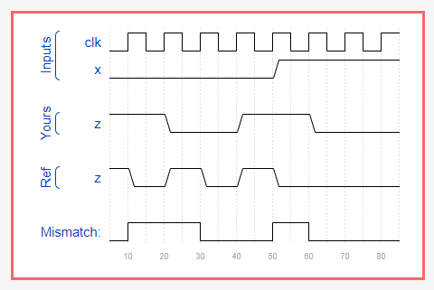
-
如果在时序逻辑中使用阻塞赋值(这是一种不应使用的写法!),输入D将初始化为0;但是在第一个时钟上沿之前 $Q=0, $ 且 \(\bar{Q}=0\),然后导致所有运算虽然正确但是出现一个周期的延迟。 (图是用网站的仿真输出的\(\bar{Q}\) 的时序图,Qbar与x无关)
always@(posedge clk)begin
    Q=D;
    Qbar=~Q;
end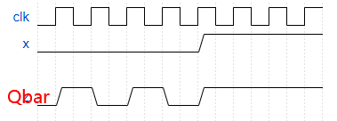
T95,edgedetect
题目要求:观察当前时钟上沿输入 \(in_n\) 与上一个时钟上沿的输入 \(in_{n-1}\) 的比特从0->1的翻转情况,并在当前周期内表示出来。
分析:
-
首先需要一个寄存器存储上一个时钟周期的输入,那么我们显是的写出一个 D触发器(触发器就是寄存器!)。
reg [7:0]Q,D; always@(posedge clk) D<=in; assign Q=D; -
观察比特 从 0->1 的翻转情况。
-
首先,用与门作掩码提取上轮和当轮皆为1的比特,有
(in&Q)。注:Q为D触发器的输出。 -
然后对上述比特位求反,并与新的输入相与即可得到新从0->1的比特。即,
(~(Q&in))&in。 -
将
(~(Q&in))&in展开化简,得到(~Q&in)。//Q.E.D
- 当然,因为新翻转的比特按照定义不可能是上轮输入中为1的比特,所以我们也可以先对上轮的输入求反,然后以此作为掩码去提取当轮输入中为1的比特。这样可以直接解释
(~Q&in)的意义。
-
T96,Edgedetect2
这题和上题类似,其中 (~Q&in) 对比当轮和前一轮输入中从0->1变化的比特,(Q&(~in)) 对比当轮和前一轮输入中从1->0 变化的比特并将这些位置的比特置为1。
always@(posedge clk)
	anyedge<= Q==in?{$bits(anyedge){1'b0}}:
        (~Q&in)|(Q&(~in));
T98,dualedge
A dual-edge triggered flip-flop is triggered on both edges of the clock.
However, FPGAs don't have dual-edge triggered flip-flops, and always @(posedge clk or negedge clk) is not accepted as a legal sensitivity list.
Build a circuit that functionally behaves like a dual-edge triggered flip-flop.

不允许同时使用一个时钟信号的上沿和下沿作为敏感列表=>那就
- 分别使用时钟上沿和下沿构造两个触发器去存储那些值,
- 根据情况选择使用哪个值。本题的判断依据是时钟电平的高低。
- 注:通过这种方式实现的双沿敏感触发器和真正的触发器是不完全等价的。触发器的输出没有毛刺(glitches),但是一个更大模拟出这种行为的组合电路(也就是本题这种实现)可能有毛刺。只是这里忽略了这些细节。
呆码如下:
module top_module (
    input clk,
    input d,
    output q
);
    reg temp1,temp2;
    always@(posedge clk)
		temp1<=d;
    always@(negedge clk)
        temp2<=d;

    always@(temp1,temp2)
        q=clk?temp1:temp2;
endmodule
参考答案利用异或运算的性质节约了一个2-1选择器。其实也是密码学(尤其是流密码、一次一密)里很常用的手段啊。
module top_module(
	input clk,
	input d,
	output q);

	reg p, n;

	// A positive-edge triggered flip-flop
    always @(posedge clk)
        p <= d ^ n;

    // A negative-edge triggered flip-flop
    always @(negedge clk)
        n <= d ^ p;

    // Why does this work?
    // After posedge clk, p changes to d^n. Thus q = (p^n) = (d^n^n) = d.
    // After negedge clk, n changes to p^n. Thus q = (p^n) = (p^p^n) = d.
    // At each (positive or negative) clock edge, p and n FFs alternately
    // load a value that will cancel out the other and cause the new value of d to remain.
    assign q = p ^ n;


	// Can't synthesize this.
	/*always @(posedge clk, negedge clk) begin
		q <= d;
	end*/


endmodule
Counters
以下复位无特殊说明时不指全局复位信号reset,而是指内部将计数器在一个周期结束后置为初值的信号。
T99,Count15 使用4位计数器,初值为0,取值为0-f,周期为16;此时不需要考虑复位(取值为16的上溢出相当于复位);
always@(posedge clk)
	if(reset)
		q<= 4'h0 ;
	else
		q<= q+1'b1 ;
T100,Count10使用4位计数器,初值为0,取值为0-9,周期为10;此时需要考虑复位的条件;
always@(posedge clk)
    if(reset)
        q<= 0;
	else
        q<=(q==4'h9)? 1'b0 : q+1'b1 ;
T101,Count1to10使用4位计数器,初值为1,取值为1-10,周期为10;此时需要考虑复位的条件,及复位的值(本题为1);
always@(posedge clk)
	if(reset)
		q<= 4'h1;
	else
        q<= (q==4'ha)? 4'h1 : q+1'b1 ;
T102,Countslow使用4位计数器,初值为0,取值为0-9,周期为10;此时需要考虑复位的条件,复位的值,以及使能信号(slowena)控制计数的开始和暂停;
always@(posedge clk)
	if(reset)
		q<= 0 ;
    else if (slowena)
        q<= (q==4'h9)? 1'b0 : q+1'b1 ;
T103,(Exams/ece241 2014 q7a)Counter1-12 通过实例化一个4位计数器实现,初值位1,取值为1-12,周期为12;此时需要考虑复位的条件,复位的值,以及使能信号;
注:下面c_d的理解参考HDLBits:在线学习 Verilog (二十一 · Problem 100 - 104) - 知乎 评论区的R-叶六一。
assign c_enable=enable;
assign c_load=reset|((Q==4'hc)&&(enable==1)); //复位的条件
assign c_d      = 4'b1;						  //复位的值
count4 the_counter (clk, c_enable, c_load, c_d,Q );
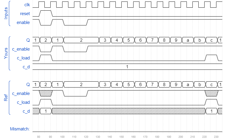
T104,(Exams/ece241 2014 q7b)Counter1000 用 模十的BCD 计数器 实现 时钟分频。注意到 时钟分频 需要的控制信号本质也是一种使能信号。呆码及其思路与下一题的高度相似,所以就不放了。
Build the frequency divider using modulo-10 (BCD) counters and as few other gates as possible.
T105,Countbcd 为一个 4-digit BCD 计数器。每个 digit 用 4- bits 表示。初值为0,取值为0-999,周期为1000;此时需要考虑复位的条件,复位的值,外部的使能信号以及分频信号,以及 T104 提到的 BCD计数器 的具体实现(参考T100)。
module top_module (
    input clk,
    input reset,   // Synchronous active-high reset
    output [3:1] ena,
    output [15:0] q);

    assign ena[1]= (q[3:0]==4'h9)?1:0;	// 逢9进1
    assign ena[2]= (q[7:4]==4'h9)&&(q[3:0]==4'h9)?1:0; //逢99进1
    assign ena[3]=	(q[11:8]==4'h9)&& (q[7:4]==4'h9)&&(q[3:0]==4'h9)?1:0; //逢999进1

    decade_counters ones		(clk,reset,1'b1,  q[3:0]);	//always add 1
    decade_counters tens		(clk,reset,ena[1],q[7:4]);
    decade_counters hundreds	(clk,reset,ena[2],q[11:8]);
    decade_counters thousands	(clk,reset,ena[3],q[15:12]);

endmodule

module decade_counters (
    input clk,
    input reset,        // Synchronous active-high reset
    input enable,
    output [3:0] q);

    always@(posedge clk)
        if(reset)
            q<=0;
        else
            q<=enable?(q==4'h9)?0:q+1'b1
            	:q;
endmodule
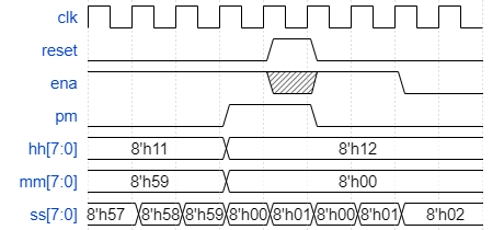
T106,一个 12小时制时钟。
题干:
reset 置时钟为 12:00AM;reset 权限高于 enable ,即可以在 enable=0 时 reset
pm=0 时表 AM,pm=1 时表 PM
hh,mm,ss, 为两位 BCD digits,分别有 hours (01-12), minutes (00-59), and seconds (00-59)
The following timing diagram shows the rollover behaviour from 11:59:59 AM to 12:00:00 PM and the synchronous reset and enable behaviour.
Hint. Note that 11:59:59 PM advances to 12:00:00 AM, and 12:59:59 PM advances to 01:00:00 PM. There is no 00:00:00.
呆码
module top_module(input clk,input reset,input ena,output pm,output [7:0] hh,output [7:0] mm,output [7:0] ss);
    wire ena_min,ena_hour;
    wire [7:0]ini_hh;
    any_counters second	(clk, reset, ena&&1'b1,		8'h00,  8'h59, ss, ena_min);
    any_counters minute	(clk, reset, ena&&ena_min,	8'h00,  8'h59, mm, ena_hour);
    assign ini_hh=reset?8'h12:8'h01;
    any_counters hour	(clk, reset, ena&&ena_hour,	ini_hh,	8'h12, hh, );
    always@(posedge clk)
        if(reset)
            pm<=0;
    	else
        pm<=(hh==8'h11)&&ena_hour?~pm:pm;
endmodule

module any_counters(input clk,input reset,input enable,input [7:0] c_d,input [7:0] cnt,output[7:0] q,output cout);
    wire ena_tens;
    decade_counters ones(clk,reset|cout,enable&&1'b1,c_d[3:0],q[3:0],ena_tens);
    decade_counters tens(clk,reset|cout,enable&&ena_tens,c_d[7:4],q[7:4],);
    assign cout=(q==cnt)&&enable?1'b1:1'b0;
endmodule

module decade_counters (input clk,input reset,input enable,input [3:0] c_d,output [3:0] q,output cout);
    always@(posedge clk)
        if(reset)
            q<=c_d;
        else
            q<=enable? ((q==4'h9)?1'b0:q+1'b1)  :q;
    assign cout=(q==4'h9)?1'b1:1'b0;
endmodule
分析:
-
本题非常综合,用到了前面各个小题的某些思路,尤其是 T103 的 1-12计数器设计,以及 T105 的分频及模块结构的设计。
-
时、分、秒部分使用时序逻辑,利用时钟分频实现;pm信号,使用组合逻辑;
-
强调
reset权限高于enable即指明了在判断控制信号的时候应该先判断 reset 后判断 enable,显式考虑并说明这一点是重要的!(当然,常见代码确实首先判断是否reset,这是合理的,因为上电后应该先全局复位,统一一下)。 -
需要的模块,1-digit-BCD counter --> 周期在(1-100)中任意的的 2-digit-BCD-counter
-
1-digit-BCD counter需要的端口,input:clk,reset,enable,[3:0]c_d; output: [3:0]q,cout
-
其中 input 中的 c_d 为复位的值;output 中的 cout 为 一个周期完成的信号(也可以理解为一个进位信号)
-
该模块的功能为,在0-9范围内循环 +1;若被复位信号复位到了指定值,则从指定值开始 +1 。所以该模块没有一个周期的概念,它只忠诚的执行 +1 操作。
-
我认为不在该模块中引入周期的概念是合理的,因为它没法解决周期为 12 的
hh,所以周期应当交给上层模块解决。但同时为了解决周期为 12 的初始化问题,所以这个模块需要可以指定 复位值,而不是恒为
0。
-
-
2-digit-BCD-counter (any_counters)封装了 1-digit-BCD counter,并通过在上述模块的输入列表中增加 [7:0] 引入了周期的概念,此时周期范围为(1-100)。
-
该模块的功能为,周期为 (1-100)的 2-digit-BCD 计数器。
-
通过增加 L19:
assign cout=(q==cnt)&&enable?1'b1:1'b0;控制周期;L12 的写法同理(注意到 ena_hour 为1时,显然全局的 ena 为1,但是 ena_hour 控制的粒度更细)。-
注意到判断条件中 与上了enable 以保证 被分频 的对象最后一个取值执行顺利,否则bug如下时序图所示。
假设此处 ss 周期为3,mm周期为9,然而可以看到依据 ss 分频的 mm ,在 mm=2 时出现了问题。

-
-
-
-
秒针的本质是一个周期为 60 的counter,分针是基于秒针分频的一个周期为 60 的counter,初值皆为
8'h00,范围为00-59,可以把这两部分理解为 60 进制,基本类似 T105。 -
时针是12进制,范围为
01-12,正常运作时初值为01,全局reset时初值为12!所以这里需要对 hh 的复位初值做一个分类讨论! -
pm信号周期为12,范围为
12->01->...->11-
L12:
pm<=(hh==8'h11)&&ena_hour?~pm:pm;刻画了 11:59:59->12:00:00 时,pm翻转-
hh==8'h11确保现在是 11点多(i.e. 刻画的是电平信号的条件),ena_hour确保现在时钟该进位至 12点(i.e. 刻画了跳变的过程)。注意这里的 level-sensitive(电平敏感) 和 edge-sensitive(边沿敏感)的刻画方式和使用方式。类似分析详见T85题解的表格。
-
-
其它:
- BCD(09) + 8'h01 ≠ BCD(10) ! BCD 和 普通二进制乱加得不到想要的结果的= =。
- HDL bits的题目中,对于多个输出,如果只有一个输出有问题,将会更详细的给出它具体的出错点。所以建议报错显示哪个output的问题点就先解决那个output,然后逐个击破。
- 对于周期为 60 的,可以先写成周期为 3 便于验证逻辑上的正确性。
Shift Registers
T110,lfsr5
伽罗瓦线性反馈移位寄存器. 定义: A Galois LFSR is one particular arrangement where bit positions with a "tap" are XORed with the output bit to produce its next value, while bit positions without a tap shift. If the taps positions are carefully chosen, the LFSR can be made to be "maximum-length". A maximum-length LFSR of n bits cycles through 2n-1 states before repeating (the all-zero state is never reached).
The following diagram shows a 5-bit maximal-length Galois LFSR with taps at bit positions 5 and 3. (Tap positions are usually numbered starting from 1). Note that I drew the XOR gate at position 5 for consistency, but one of the XOR gate inputs is 0.

Build this LFSR. The reset should reset the LFSR to 1.
The first few states starting at 1 are 00001, 10100, 01010, 00101, ... The LFSR should cycle through 31 states before returning to 00001.
题解亮点:
-
组合逻辑和时序逻辑结合的典范
-
注意在
always@(*)中,组合逻辑可以覆盖赋值(L15-17)
module top_module(
	input clk,
	input reset,
	output reg [4:0] q);

	reg [4:0] q_next;		// q_next is not a register

	// Convenience: Create a combinational block of logic that computes
	// what the next value should be. For shorter code, I first shift
	// all of the values and then override the two bit positions that have taps.
	// A logic synthesizer creates a circuit that behaves as if the code were
	// executed sequentially, so later assignments override earlier ones.
	// Combinational always block: Use blocking assignments.
	always @(*) begin
		q_next = q[4:1];	// Shift all the bits. This is incorrect for q_next[4] and q_next[2]
		q_next[4] = q[0];	// Give q_next[4] and q_next[2] their correct assignments
		q_next[2] = q[3] ^ q[0];
	end


	// This is just a set of DFFs. I chose to compute the connections between the
	// DFFs above in its own combinational always block, but you can combine them if you wish.
	// You'll get the same circuit either way.
	// Edge-triggered always block: Use non-blocking assignments.
	always @(posedge clk) begin
		if (reset)
			q <= 5'h1;
		else
			q <= q_next;
	end

endmodule
T113 (Exams/m2014 q4k) shift register
题干:Implement the following circuit:

题解亮点:意义明确的临时变量名,及注释说明的本题各操作的现实意义.
注:本题不关心是左移还是右移实现。即下方L15也可以写作 sr<={in,sr[3:1]}; 。
module top_module (
	input clk,
	input resetn,
	input in,
	output out
);

	reg [3:0] sr;

	// Create a shift register named sr. It shifts in "in".
	always @(posedge clk) begin
		if (~resetn)		// Synchronous active-low reset
			sr <= 0;
		else
			sr <= {sr[2:0], in};
	end

	assign out = sr[3];		// Output the final bit (sr[3])

endmodule
T115,(Exams/ece241 2013 q12)3-input LUT
The final circuit is a shift register attached to a 8-to-1 mux.
module top_module (
	input clk,
	input enable,
	input S,

	input A, B, C,
	output reg Z
);

	reg [7:0] q;

	// The final circuit is a shift register attached to a 8-to-1 mux.

	// Create a 8-to-1 mux that chooses one of the bits of q based on the three-bit number {A,B,C}:
	// There are many other ways you could write a 8-to-1 mux
	// (e.g., combinational always block -> case statement with 8 cases).
	assign Z = q[ {A, B, C} ];

	// Edge-triggered always block: This is a standard shift register (named q) with enable.
	// When enabled, shift to the left by 1 (discarding q[7] and and shifting in S).
	always @(posedge clk) begin
		if (enable)
			q <= {q[6:0], S};
	end

endmodule
More Circuits
参考资料:HDLBits:在线学习 Verilog (二十四 · Problem 115-119) - 知乎
T116,Rule90
法一(我的写法):
    always@(posedge clk)
        if(load)
            q<=data;
    else
        q<={q[510],q[511:2]^q[509:0],q[1]};
法二(标答的写法):
结果的正确性说明:q[511:1]只有511位,异或对象是512位,自动扩展——在高位补0,所以q[511:1]在这里会转换为{1'b0,q[511:1]}
	always @(posedge clk) begin
		if (load)
			q <= data;	// Load the DFFs with a value.
		else begin
			// At each clock, the DFF storing each bit position becomes the XOR of its left neighbour
			// and its right neighbour. Since the operation is the same for every
			// bit position, it can be written as a single operation on vectors.
			// The shifts are accomplished using part select and concatenation operators.

			//     left           right
			//  neighbour       neighbour
			q <= q[511:1] ^ {q[510:0], 1'b0} ;
		end
	end
法三:
可进一步利用移位补0的特点化简代码。(由参考资料评论区的 一苇所如 提供。)
always @(posedge clk)
    if (load)
        q <= data;
    else
        q <= (q<<1)^(q>>1);
T117,Rule110
法一:
我觉得我这个用查表这个办法蛮好的。
module top_module(
    input clk,
    input load,
    input [511:0] data,
    output [511:0] q
);

    wire [7:0]mem;
    assign mem=8'b01101110;
    always@(posedge clk)begin
        if(load)
            q<=data;
    	else begin
            q[0] <= mem[{q[1],q[0],1'b0}];
            q[511] <= mem[{1'b0,q[511],q[510]}];
            for(int i=1;i<511;i++)
                q[i] <= mem[{q[i+1],q[i],q[i-1]}];
        end
    end

endmodule
法二:
利用卡诺图化简真值表,以有限状态机的思路/风格 写代码。(省略接口部分)
reg [511:0]l_fei,r;
reg [511:0]current_state,next_state;

assign q=current_state;

always @(posedge clk)
    if(load)
        current_state<=data;
else
    current_state<=next_state;

always @(*) begin
    l_fei = ~{1'b0,current_state[511:1]};
    r = {current_state[510:0],1'b0};
    next_state=current_state^r|(r&l_fei);
end
T118,Conwaylife(康威生命游戏)
最终版代码。主要不喜欢写太多分支判断,所以选择了【先写一个填充矩阵,然后按照要求遍历】这个比较暴力的做法。
module top_module(
    input clk,
    input load,
    input [255:0] data,
    output [255:0] q );

    reg [323:0]tmp_q;   //padding q with the rollover, a 18*18 grid
    reg [255:0]update;

    //padding a new grid to deal with the roll over part
    always@(posedge clk)begin
        for(int i=1;i<17;i++)
            {tmp_q[i*18],tmp_q[i*18+1+:16],tmp_q[i*18+17]}  <= {update[(i-1)*16+15],update[(i-1)*16+:16],update[(i-1)*16]};
        //padding the first row which contains (15,15),(15,0) => (15,15),(15,0)
        {tmp_q[0],tmp_q[16:1],tmp_q[17]}                    <= {update[255],update[255-:16],update[240]};
        //padding the last row which contains (0,15),(0,0)  => (0,15),(0,0)   ,
        {tmp_q[306],tmp_q[322-:16],tmp_q[323]}              <= {update[15],update[15:0],update[0]};
    end

    //count neighbours, and compute q_next
    reg [3:0]sum;
    always@(*)begin
        sum=
        if(load)
            update=data;
        else begin
            //count neighbours
            int i,j;//i->row, j->column
            for (i=1;i<17;i++)begin
                for(j=1;j<17;j++)begin
                    sum= tmp_q[(i-1)*18+(j-1)]+tmp_q[(i-1)*18+(j)]+tmp_q[(i-1)*18+(j+1)]
                        +tmp_q[i*18+(j-1)]+tmp_q[i*18+(j+1)]
                        +tmp_q[(i+1)*18+(j-1)]+tmp_q[(i+1)*18+(j)]+tmp_q[(i+1)*18+(j+1)];
                    //compute q_next and saved in the update
                    case(sum)
                        4'b0010: update[(i-1)*16+(j-1)] = tmp_q[i*18+(j)];
                        4'b0011: update[(i-1)*16+(j-1)] = 1'b1;
                        default: update[(i-1)*16+(j-1)] = 1'b0;
                    endcase
                end
            end
        end
    end

    //assign the result to q
    always@(*)
        for(int i=1;i<17;i++)
            q[(i-1)*16+:16] = tmp_q[i*18+1+:16];
endmodule
这个写法将问题转换为矩阵填充和遍历。逻辑本身没有难点。
对于硬件描述语言实现,卡壳点在于 L35 一开始写成了 update[(i-1)*16+(j-1)] = update[(i-1)*16+(j-1)]; 这引发了一个锁存器;进一步,该锁存器引发了一系列我预料之外难以理解的bug,就困扰了很多天。
-
(FPGA中Verilog语言综合出锁存器的问题 - 知乎)
首先是什么是锁存器的问题。是一种对脉冲电平敏感的存储单元电路,它们可以在特定输入脉冲电平作用下改变状态。锁存,就是把信号暂存以维持某种电平状态。另外一种对脉冲电平信号变化敏感的存储单元电路叫触发器,它的功能和锁存器类似。但是,FPGA中综合出锁存器,具有如下几种危害:
对毛刺敏感,不能异步复位,所以上电以后处于不确定的状态;
Latch没有时钟信号,会使静态时序分析变得非常复杂;
在PLD芯片中,基本的单元是由查找表和触发器组成的,若生成锁存器反而需要更多的资源。
因此在设计的过程中,应该避免综合出锁存器。锁存器的功能可以用组合逻辑电路和触发器替代。
大家一致避免使用的锁存器为什么依然存在于FPGA中?我们对锁存器有什么误解? - 知乎
对毛刺敏感的示意图
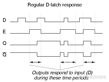
对比触发器只在时钟边沿时起作用,所以哪怕输入的信号中有毛刺,输出还是比较干净的。

-
大家一致避免使用的锁存器为什么依然存在于FPGA中?我们对锁存器有什么误解? - 知乎
- FPGA中最小的单元是门电路,门电路又组成了锁存器,锁存器组成了寄存器。
- 在写状态机时,常有case语句中没有给出变量的全部情况,进而生成 锁存器。
- (详见原文)为什么锁存器依然存在于FPGA中?/ 我们以下面的代码来说明Flip-Flop和Latch在Ultrascale的FPGA中Implementation后的结果。
- 既然Latch有这么多的问题,那为什么FPGA中还要保留?
- 首先就是因为FPGA电路的灵活性,保留Latch并不影响FPGA的资源,因为storage element可以直接被配置为Flip-Flop。
- 其次就是有些功能是必须要使用Latch的,比如很多处理器的接口就需要一个Latch来缓存数据或地址。
- 锁存器虽然在FPGA中不怎么被使用,但在CPU中却很常见,因为锁存器比Flip-Flop快很多。
-
-
问1:是不是所有的代码,if else都需要补全呢?
答:如前面所讨论的,对于时序逻辑可以由D寄存器实现“保持不变”,所以时序逻辑是不需要补全的,只有组合逻辑才需要。
问2:是不是只要组合逻辑的if else补充了,就不会生成锁存器了?
答:不一定。这里的关键在于“保持不变”,千万不要从“代码层次”来理解,而应该从“功能的层次”来理解,要找准到底有没有“保持不变”。 例如,下面的代码,虽然else写上去了,但写不写else都是让b保持不变。所以这仍然会综合出锁存器。
always@(*)
if (a==1)
  b=1;
	else
  b=b;
问5:功能上,我一定要实现“组合逻辑的保持不变”功能,该如何做?
答:通常来说,所谓“组合逻辑的保持不变”,是指“该段代码”是组合逻辑写的,但需要与前一个时钟的值保持不变,如下代码,这种需求是很正常的。
always@(*)
if (a==1)
  b=1;
	else
  b=上一个时钟周期的值;
解决方法,仍然是靠D触发器来实现“保持不变”的功能。只不过是把一个时序逻辑的ALWAYS写法,换成组合逻辑+时钟逻辑的写法而已,代码如下。
always@(*)
if (a==1)
  b=1;
	else
  b=b_reg;

always@(posedge clk, negedge rst_n)
if(rst_n==1'b0)
  b_reg <= 0;
	else
  b_reg <= b;
//Yx: ↓这条持保留意见。
问6:问题5的扩展,我就是要实现组合逻辑的保持,并且小于一个时钟周期的。
答:不正常需求,FPGA不会这么设计的。
-
-
从代码和电路图看实现出的东西及锁存器。


