HDLBits-Verilog Practice-1-Getting started -> Circuits.Combinational Logic
注:建议使用 Ctrl+F 利用关键词、题号、题目名称 查阅本文内容
笔记内容
-
本文范围 Getting started -> Circuits.Combinational Logic
-
网页本身给出的语法点,和一些语法的使用思路
-
做题过程中的反思
-
参考答案xiaop1/Verilog-Practice: HDLBits website practices & solutions
待归档内容
-
组合逻辑 写进 always块 的 敏感列表
-
(在某次编译时候看到的warning)
You used a signal in an always block but didn't add it to the sensitivity list. Just use
always@(*)and let the compiler deal with it. Quartus will use the correct sensitivity list, but Modelsim and other simulators won't, leading to a mismatch between simulation and logic synthesis, which is incredibly hard to debug. -
Alwaysblock1 - HDLBits 中相反的观点,For combinational always blocks, always use a sensitivity list of (*).Explicitly listing out the signals is error-prone (if you miss one), and is ignored for hardware synthesis. If you explicitly specify the sensitivity list and miss a signal, the synthesized hardware will still behave as though
(*)was specified, but the simulation will not and not match the hardware's behaviour. (In SystemVerilog, usealways_comb.)
-
-
其它:
-
Vivado下试出来的几条 Verilog 综合的规则_Tiger-Li的博客-CSDN博客
总体原则:操作要与输出信号相关,不相关的全部视为无用信号,综合成电路是被综合掉。
1,always过程中 中间变量自己给自己赋值的操作,在综合出来的电路中会被忽略掉, 因为对电路的输出没有意义。
2,输入信号赋值给中间变量, 但是没有跟输出相关,被综合掉。
3,中间变量赋给常量值,在综合时会根据位值 直接连接对应位D触发器的set信号,使D触发器常量,而不会连接跟clk有关的D信号。
4,语句的书写顺序与执行顺序无关,但是与综合顺序有关,如果发生冲突,例如两个信号同时连接到输出信号, 那么后面书写的语句会将前面书写的语句生成的电路覆盖掉。
5,输入信号,中间结果赋给中间变量,只要这个中间变量最后与输出有关,就会在中间生成触发器来存储,这个就是写流水线的方法。
-
Getting started
编译工具 Quartus
仿真工具 ModelSim, 用于验证
Verilog Language
Basics
笔记
这一部分题重在体会 硬件描述语言 是如何描述硬件的,硬件有什么是可以描述的,需要见微知著。纯粹用高级语言的思路刷题当然很快,但是日后就会犯一些思维不同的隐蔽的错误。
T3,Wire
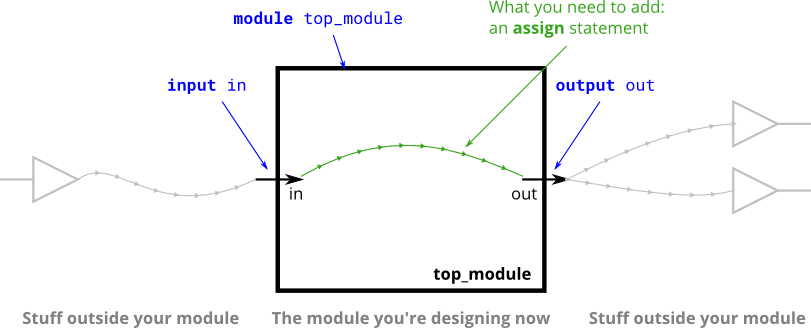
不像生活中物理意义上的导线,Verilog中的wire是有方向的。即,信息流从一边进(源也称为 driver)到另一边出(称为sink)。
T4,Wire4
assign 语句中的持续性”赋值”语句 的本质是连线/连接(connection),而不是高级语言中的拷贝赋值。
Unlike a programming language, assign statements ("continuous assignments") describe connections between things, not the action of copying a value from one thing to another.
T3 图中的绿色带箭头的线 表示wires之间的关系(connection),而不是wire本身。声明的黑色输入输出端口才是wire(除非端口被声明为reg类型。注:这个reg不是真的寄存器,只是一个verilog历史遗留的语法(syntax))。
T5,Notgate
verilog中,“!”表示逻辑求反,“~”表示按位求反。当对位宽为1的变量进行操作时,这两个操作符的作用是一样的,都是求反。当对位宽为2的变量a[1:0]进行操作时,这两个操作符的作用就不一样了:“!”表示 ~(a[0] | a[1]),只有当a的每一位都为0时,结果才为1,条件判断中 if(!a) 等价于 if(a == 0);“~”表示对每一位按位取反,只有当a的每一位都为1时,结果才为0。
注:与门、或门同理。
T6,Andgate
-
As you might expect, a wire cannot have more than one driver (what is its logic level if there is?)
这里是硬件描述语言!所以 wires 不像C语言中的变量可以多次用不同的statement去“赋值”!一个wire若有多个驱动(driver),则会报错 Multiple Driver Nets:

注意到一个wire不能有多个driver不代表这个wire的输出是一个恒定不变的值。wire a 连线至 wire b 后,输入改变,输出也将改变,所以wire b的值是可以变的。
所以这题讲完上述,引入了与门!!!两个 input driver通过某种关系映射成一个去驱动output。
-
and a wire that has no drivers will have an undefined value (often treated as 0 when synthesizing hardware).
此外,没有驱动的 wire 综合时一般置0.
T7,Norgate
-
net 是 wire 的正式称呼,中文常翻译为线网。
-
组合电路,就是无记忆性的,没有隐藏状态
combinational (i.e., memory-less, with no hidden state)
T9,Declaring Wires
-
(In the future, you will encounter more types of signals and variables that are also declared the same way, but for now, we'll start with a signal of type wire).
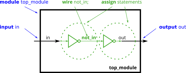
新的 wire 需在使用前声明,新的 wire 可用来连接内部的模块——这点可在日后多加体会它与高级程序语言中的变量的不同之处。
-
Notice how wires are driven by exactly one source (output of a gate), but can feed multiple inputs.
这在 T6 的第一点中也有谈到过
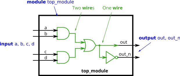
注:这当然也可以不用许多中间wires来实现。
题目:step_one
显示的写出数据宽度1'和数据表示形式为二进制b是一个好习惯
assign one = 1'b1;
题目:wire4
对于下面的
assign w = a;
assign x = b;
assign y = b;
assign z = c;
如果确切知道每个信号的宽度,使用下面这个写法会更简介
assign {w,x,y,z} = {a,b,b,c};
Vectors
笔记
向量、级联、复制这三个工具一套组合拳!大杀器!
T11,12, Vector0, Vector1
Vectors are used to group related signals using one name to make it more convenient to manipulate. For example,
wire [7:0] w;declares an 8-bit vector namedwthat is equivalent to having 8 separate wires.
引入 向量(vector) 概念,通过索引更便于操作变量。对比T12提到的 packed 和unpacked array
type [upper:lower] vector_name;
type 多为 wire 或 reg。
[upper:lower]
- 为可变向量域(参考 2.3 Verilog 数据类型 | 菜鸟教程 );
upper>lower=>小端,upper<lower=>大端;两种声明方式都可以,但后续索引切片方式必须和声明方式一致:writingvec[1:2]whenvecis declaredwire [3:0] vec;is illegal.- 声明向量大小端方式的一致性很重要,否则会导致奇怪的bug。
声明向量(Declaration)示例。
//T11
wire [99:0] my_vector;      // Declare a 100-element vector

//T12
reg  [4:1] x;         // 4-bit reg
output reg [0:0] y;   // 1-bit reg that is also an output port (this is still a vector)
input wire [3:-2] z;  // 6-bit wire input (negative ranges are allowed)
output [3:0] a;       // 4-bit output wire. Type is 'wire' unless specified otherwise.
wire [0:7] b;         // 8-bit wire where b[0] is the most-significant bit.
注:大小端看的是LSB(Least Significant Bit),小端(little-endian)要求LSB有lower index,大端(Big-endian)反之。
索引向量(Part-Select)示例。
assign w = a;
使用向量名字访问整个向量。连线时,若左右选择的数据长度不匹配,会进行截断或者0扩展(是0扩展,而不是符号位扩展,因为在当前这个层次,我们没有 signed int 和 unsigned int的概念,只有比特0和1)。
其它示例,
//T11
assign out = my_vector[10]; // Part-select one bit out of the vector

//T12
//Declaration
wire [7:0] w;         // 8-bit wire
reg  [4:1] x;         // 4-bit reg
input wire [3:-2] z;  // 6-bit wire input (negative ranges are allowed)
wire [0:7] b;         // 8-bit wire where b[0] is the most-significant bit.

//Part-Select
w[3:0]      // Only the lower 4 bits of w
x[1]        // The lowest bit of x
x[1:1]      // ...also the lowest bit of x
z[-1:-2]    // Two lowest bits of z
b[3:0]      // Illegal. Vector part-select must match the direction of the declaration.
b[0:3]      // The *upper* 4 bits of b.
assign w[3:0] = b[0:3];    // Assign upper 4 bits of b to lower 4 bits of w. w[3]=b[0], w[2]=b[1], etc.
隐式线网 Implicit nets
避免它的方式是使用指令(directive) `default_nettype none
未声明就使用(通过 assign 语句或与 module port 相连接)的符号默认为 1bit wire 类型,将和我们预期的向量类型不符,从而导致bug。
bug示例:
wire [2:0] a, c;   // Two vectors
assign a = 3'b101;  // a = 101
assign b = a;       // b =   1  implicitly-created wire
assign c = b;       // c = 001  <-- bug
my_module i1 (d,e); // d and e are implicitly one-bit wide if not declared.
                    // This could be a bug if the port was intended to be a vector.
Unpacked vs. Packed Arrays
You may have noticed that in declarations, the vector indices are written before the vector name. This declares the "packed" dimensions of the array, where the bits are "packed" together into a blob (this is relevant in a simulator, but not in hardware). The unpacked dimensions are declared after the name. They are generally used to declare memory arrays. Since ECE253 didn't cover memory arrays, we have not used packed arrays in this course. See http://www.asic-world.com/systemverilog/data_types10.html for more details.
reg \[7:0\] mem \[255:0\];   // 256 unpacked elements, each of which is a 8-bit packed vector of reg.
reg mem2 \[28:0\];         // 29 unpacked elements, each of which is a 1-bit reg.
注:packed array types cannot assigned to unpacked array types! 表明 wire [31:0]a; wire b[31:0]; 是两种东西,也就不能写 assign a=b;
T13,Vector2
考虑字节为单位的循环移位,常是因为 不同协议之间的大小端规定不同,需要转换。AaaaaaaaBbbbbbbbCcccccccDddddddd => DdddddddCcccccccBbbbbbbbAaaaaaaa
T16,Vector3
需要知道每个元素的位宽(否则无法知道结果的位宽),因此没有注明数据位宽的 {1,2,3} 是违法的。
级联将引发0扩展如 Line:5 所示,
input [15:0] in;
output [23:0] out;
assign {out[7:0], out[15:8]} = in;         // Swap two bytes. Right side and left side are both 16-bit vectors.
assign out[15:0] = {in[7:0], in[15:8]};    // This is the same thing.
assign out = {in[7:0], in[15:8]};       // This is different. The 16-bit vector on the right is extended to match the 24-bit vector on the left, so out[23:16] are zero. In the first two examples, out[23:16] are not assigned.
T18,Vector4
Replication vector,复制操作
语法:{num{vector}}
num 必须是常量;两对花括号都是必要的;
示例:
{5{1'b1}}           // 5'b11111 (or 5'd31 or 5'h1f)
{2{a,b,c}}          // The same as {a,b,c,a,b,c}
{3'd5, {2{3'd6}}}   // 9'b101_110_110. It's a concatenation of 101 with
                    // the second vector, which is two copies of 3'b110.
该操作常用来扩展最高位。(因为级联默认的是0扩展!)
题目:Vector1
第 n+1次 忘记写级联(concatenation)。
不简洁的写法
assign out_hi = in[15:8];
assign out_lo = in[7:0];
和简洁的写法
// Concatenation operator also works:
assign {out_hi, out_lo} = in;
Modules: Hierarchy
笔记
T20,Module
复杂电路通过小模块等其它组件(assign语句和过程块)构成。这构成 层次结构(hierarchy),因为一个模块可以包括其它模块的实例化(可以一直嵌套,只要这些模块属于同一个项目——可以被编译器找到)。
实现不同模块的功能呆码不可以嵌套。
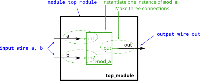
实例化模块的两种方式:建议养成 通过名字实例化 的习惯。
-
通过位置,
mod_a instance1 ( wa, wb, wc );优点:简洁;缺点:可扩展性差——一旦模块的端口列表顺序有调整,所有实例都得改。
-
通过名字
mod_a instance2 ( .out(wc), .in1(wa), .in2(wb) );优点:可扩展性强;缺点:冗长。
T24,Module shift8
多资源+串行+向量。(相较于 Mt2015 q4 那题,本题实际是存在门级电路延迟的)
(Essentially, sel selects how many cycles to delay the input, from zero to three clock cycles.)

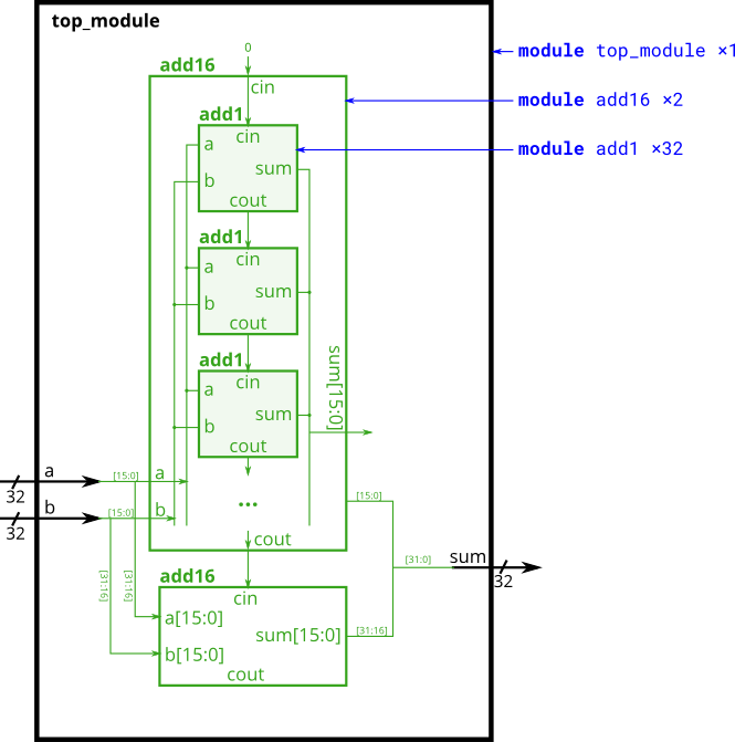
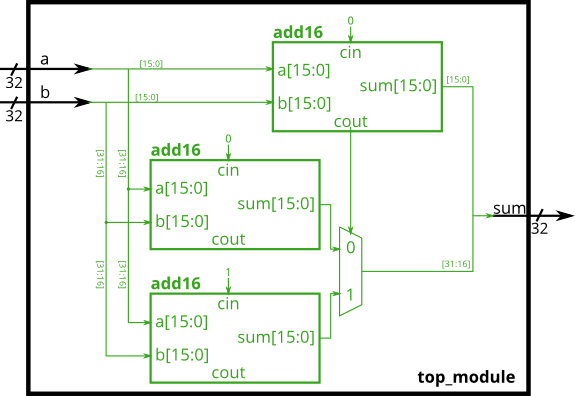
T26,module_fadd;T27,Module cseladd
放全加器的模块图,提醒自己,我们是硬件!硬件!硬件!
全加器的多种实现方式。这就是从数字逻辑到计算机组成与设计的一步。
T26
T27
Procedures
笔记
T29,Alwaysblock1
-
For synthesizing hardware, two types of always blocks are relevant:
-
Combinational: always @(*)
-
Clocked: always @(posedge clk)
-
-
Combinational always blocks 总是等价于 assign 语句。所以哪种语法方便用哪种。
-
过程块有更丰富的语法,不支持可综合的持续性赋值语法,也引入了更多写bug的方法😵.
-
Procedural blocks have a richer set of statements (e.g., if-then, case), cannot contain continuous assignments, but also introduces many new non-intuitive ways of making errors. (**Procedural continuous assignments do exist, but are somewhat different from continuous assignments, and are not synthesizable.)
-
-
无论 sensitivity list 写的是(*) 还是具体的 signal,综合时都当作*号处理,但仿真时不会这样,所以写 signal 的时候会导致仿真和实际硬件运行结果不一致。(In SystemVerilog, use
always_comb.) -
A note on wire vs. reg: assign 语句操作 wire 类型,always 块操作 reg类型,但这些类型(wire vs. reg)与合成的硬件无关,只是 Verilog 用作硬件模拟语言时留下的语法。
T30,Alwaysblock2
-
触发器(Flip-flop, FF)也称为 寄存器(register)
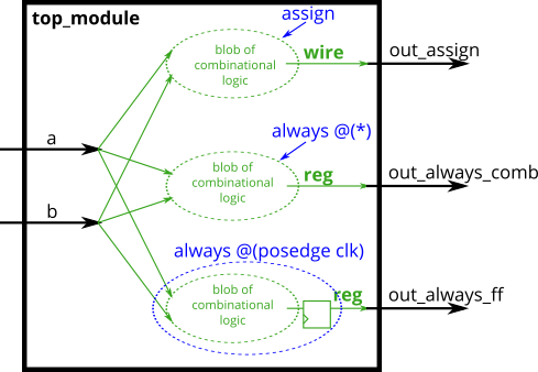
-
Verilog有三种 assignment语句
- Continuous assignments (assign x = y;). Can only be used when not inside a procedure ("always block").
- Procedural blocking assignment: (x = y;). Can only be used inside a procedure.
- Procedural non-blocking assignment: (x <= y;). Can only be used inside a procedure.
- 严格遵守In a combinational always block, use blocking assignments. In a clocked always block, use non-blocking assignments.
- 详见之前的 Verilog笔记——学习过程中的问题整理
- 完全理解为什么对硬件设计不是特别有用,并且需要很好地理解 Verilog 模拟器如何跟踪事件。
T31,Always if
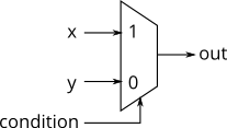
以下两种写法等价
assign out = (condition) ? x : y;
always @(*) begin
    if (condition) begin
        out = x;
    end
    else begin
        out = y;
    end
end
对于法二,提供了写bug的新思路。out 需要一直被 assign value,如果没有被 assign value,它实际上就是保持之前的value,起到了一个 锁存器的效果,锁存器是时序的。
用高级语言的思路写verilog可能导致意料之外的锁存器,进而引发其它bug。
The circuit is combinational only if out is always assigned a value.
T32 Always if2
相关题目:T36,Always nolatches
避免通过if语句造成latch
主要讲什么是锁存器,如何引入的,怎么加assign语句去消除它。Always if2 - HDLBits 原文写的比较清晰,结合下面的题解笔记看比较好。
When designing circuits, you must think first in terms of circuits:
- I want this logic gate
- I want a combinational blob of logic that has these inputs and produces these outputs
- I want a combinational blob of logic followed by a set of flip-flops
What you must not do is write the code first, then hope it generates a proper circuit.
Syntactically-correct code does not necessarily result in a reasonable circuit (combinational logic + flip-flops). The usual reason is: "What happens in the cases other than those you specified?". Verilog's answer is: Keep the outputs unchanged.
This behaviour of "keep outputs unchanged" means the current state needs to be remembered, and thus produces a latch. Combinational logic (e.g., logic gates) cannot remember any state. Watch out for Warning (10240): ... inferring latch(es) messages. Unless the latch was intentional, it almost always indicates a bug. Combinational circuits must have a value assigned to all outputs under all conditions. This usually means you always need else clauses or a default value assigned to the outputs.
T33,Always case
always @(*) begin     // This is a combinational circuit
    case (in)
      1'b1: begin
               out = 1'b1;  // begin-end if >1 statement
            end
      1'b0: out = 1'b0;
      default: out = 1'bx;
    endcase
end
- 分支中,需要执行的语句超过一句时,需要加
begin ... end. - 允许重复(和部分重叠)的跳转条件,将使用第一个匹配的。 C不允许重复的跳转条件。
T34,Always casez
示例
always @(*) begin
    casez (in[3:0])
        4'bzzz1: out = 0;   // in[3:1] can be anything
        4'bzz1z: out = 1;
        4'bz1zz: out = 2;
        4'b1zzz: out = 3;
        default: out = 0;
    endcase
end
A case statement behaves as though each item is checked sequentially (in reality, it does something more like generating a giant truth table then making gates).
- There is also a similar casex that treats both x and z as don't-care. I don't see much purpose to using it over casez.
- The digit ? is a synonym for z. so 2'bz0 is the same as 2'b?0
T36,Always nolatches
相关题目:T32 Always if2
避免case语句造成的 latch ,一种更优雅更简洁的初始化(多变量情况下写default)的方式
Simply having a default case is not enough. You must assign a value to all four outputs in all four cases and the default case. This can involve a lot of unnecessary typing. 即,每个分支和default里都要对四个变量assign,
always@(*)begin
    up = 1'b0; down = 1'b0; left = 1'b0; right = 1'b0;
    case(scancode)
        16'he06b:	begin
            up = 1'b0;
            down = 1'b0;
            left =1'b1;
            right = 1'b0;
        end
     ...
    endcase
end
One easy way around this is to assign a "default value" to the outputs before the case statement:
always @(*) begin
    up = 1'b0; down = 1'b0; left = 1'b0; right = 1'b0;
    case (scancode)
        ... // Set to 1 as necessary.
    endcase
end
This style of code ensures the outputs are assigned a value (of 0) in all possible cases unless the case statement overrides the assignment. This also means that a default: case item becomes unnecessary.
这个呆码可以理解成,case语句和up = 1'b0; down = 1'b0; left = 1'b0; right = 1'b0; 一同构成一个大的多路选择器。
Reminder: The logic synthesizer generates a combinational circuit that behaves equivalently to what the code describes. Hardware does not "execute" the lines of code in sequence.
题目:Always if2 - HDLBits
锁存器的latch示例
描述:The following code contains incorrect behaviour that creates a latch.
呆码:
always @(*) begin
    if (cpu_overheated)
       shut_off_computer = 1;
end

always @(*) begin
    if (~arrived)
       keep_driving = ~gas_tank_empty;
错误呆码对应产生的多路选择器

对应时序图
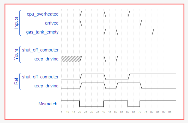
以 cpu_overheated 为例。编译器直接初始化 shut_off_computer 为1,后面,若 cpu_overheated 为真,则 shut_off_computer 为真,但是若 cpu_overheated 为假,没有对 shut_off_computer 的修改操作(所谓修改本质上通过二路选择器实现,因为 if-else 的本质是一个二(多)路选择器),所以此时 shut_off_computer 仍为真。因此, shut_off_computer 为图中所示的一条恒为 1 的直线,也就相当于一个锁存器,无论 cpu_overheated 怎么变, shut_off_computer 都为真。
注: keep_driving 一开始未定义的状态就是因为没有写else——显然,根据最初 arrived 和gas_tank_empty 的取值无法初始化 keep_driving 。由此可猜测, shut_off_computer 恒为 1 是编译器看透了之后肯定会是一个恒为 1 的锁存器后的一种化简的结果。
More Verilog Features
笔记
T38,Reduction(归约/归一/一元 运算符)
The reduction operators can do AND, OR, and XOR of the bits of a vector, producing one bit of output:
& a[3:0]     // AND: a[3]&a[2]&a[1]&a[0]. Equivalent to (a[3:0] == 4'hf)
| b[3:0]     // OR:  b[3]|b[2]|b[1]|b[0]. Equivalent to (b[3:0] != 4'h0)
^ c[2:0]     // XOR: c[2]\^c[1]\^c[0]
These are unary operators that have only one operand (similar to the NOT operators! and ~). You can also invert the outputs of these to create NAND, NOR, and XNOR gates, e.g., (~& d[7:0]).
题目:Vector100r
相关题目:Circuits -> Combinational Logic -> Vectorr
A for loop (in a combinational always block or generate block) would be useful here. I would prefer a combinational always block in this case because module instantiations (which require generate blocks) aren't needed.
以下两种写法等价,但仍有一些区别。前者涉及模块的实例化,更笨重一些。
法一
module top_module(
    input [99:0] in,
    output [99:0] out
);
	generate
        genvar i;
        for(i=0;i<100;i++)begin: reverse_in
           assign out[i]=in[99-i];
        end
    endgenerate
endmodule
法二
两个亮点:
- 在always块中写循环
- 使用$bits()函数获取变量的位宽
module top_module (
	input [99:0] in,
	output reg [99:0] out
);

always @(*) begin
	for (int i=0;i<$bits(out);i++)		// $bits() is a system function that returns the width of a signal.
		out[i] = in[$bits(out)-i-1];	// $bits(out) is 100 because out is 100 bits wide.
end

endmodule
题目:Popcount25
相关题目:Circuits -> Combinational Logic -> Basic Gates -> Popcount3 (小规模时的一题三解)
- 看到题目最直观的写法是这个。
module top_module(
    input [254:0] in,
    output [7:0] out );

    always@(*)
        begin
            out=8'h00;
            for(int i=0;i<$bits(in);i++)
                if(in[i])
                    out=out+8'h1;
            else
                out=out;
        end
endmodule
注意到 out=8'h00 实际上 对于这句的 out=out+8'h1; 的一个初始化。若不写 out=8'h00 ,根据下面这个呆码out 就始终是(状态不定的)锁存器,得到时序图及相应报错如下所示。
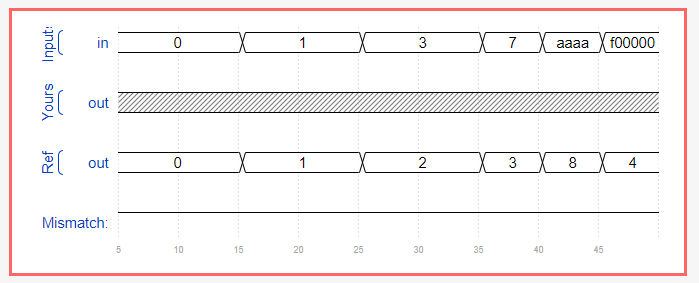
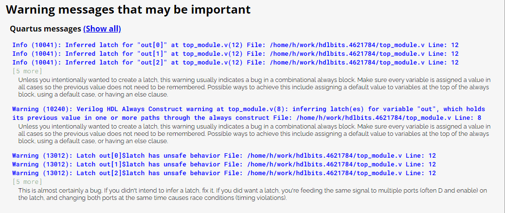
- 对于
if-else语句进一步合并,可得到标答的写法
module top_module (
	input [254:0] in,
	output reg [7:0] out
);

	always @(*) begin	// Combinational always block
		out = 0;
		for (int i=0;i<255;i++)
			out = out + in[i];
	end

endmodule
题目:Adder100i
提示:There are many full adders to instantiate. An instance array or generate statement would help here.
以下给出实例化instance向量组 和generate 语句 两种等价实现。verilog - Can we have an array of custom modules? - Stack Overflow
module top_module(
    input [99:0] a, b,
    input cin,
    output [99:0] cout,
    output [99:0] sum );
    full_adders first(a[0],b[0],cin,cout[0],sum[0]);
    generate
        genvar i;
        for(i=1;i<$bits(cout);i++)begin: adder100i
            	full_adders (a[i],b[i],cout[i-1],cout[i],sum[i]);
    end
    endgenerate


    full_adders adder100i[99:1]  (a[99:1],b[99:1],cout[98:0],cout[99:1],sum[99:1]);

endmodule

module full_adders(
    input a, b, cin,
    output cout, sum );
	assign sum=a^b^cin;
    assign cout=a&b | a&cin | b&cin;
endmodule
题目:Bcdadd100 - HDLBits
这个用到的语法挺综合的。我写的答案如下:
module top_module(
    input [399:0] a, b,
    input cin,
    output cout,
    output [399:0] sum );
    wire tmp_cout[99:0];
    bcd_fadd bcdadd_1(a[3:0],b[3:0],cin,tmp_cout[0],sum[3:0]);
    bcd_fadd bcdadd100[99:1](a[399:4],b[399:4],tmp_cout[98:0],tmp_cout[99:1],sum[399:4]);
    assign cout=tmp_cout[99];
endmodule

module bcd_fadd (
    input [3:0] a,
    input [3:0] b,
    input     cin,
    output   cout,
    output [3:0] sum );
Circuits
Combinational Logic
Basic Gates
笔记
T51,Truthtable1
组合逻辑 输出只和输入有关;一组输入仅对应一组输出。因此可以画真值表描述该逻辑电路。
Combinational means the outputs of the circuit is a function (in the mathematics sense) of only its inputs. This means that for any given input value, there is only one possible output value. Thus, one way to describe the behaviour of a combinational function is to explicitly list what the output should be for every possible value of the inputs. This is a truth table.
SOP,Sum (meaning OR) of products (meaning AND),最小与或表达式
POS,最大或与表达式
题目:Mt2015 eq2
assign z = (A[1:0]==B[1:0]); // Comparisons produce a 1 or 0 result. 等价于 assign z = A==B?1:0;
题目:Mt2015 q4
Mt2015 q4 - HDLBits 模块调用及其对应电路图。
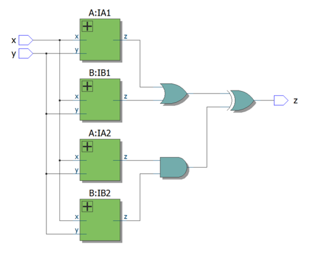
题目:Vectorr
相关题目:Verilog Language -> More Verilog Features -> Vector100r
solution中提到的一些关于 在Verilog中写循环 的二三事。
Create a combinational always block. This creates combinational logic that computes the same result as sequential code. for-loops describe circuit behaviour, not structure, so they can only be used inside procedural blocks (e.g., always block).
for循环描述的是电路的行为而不是结构。这句话可以从另一个角度理解组合逻辑和时序逻辑。组合逻辑描述的是结构,时序逻辑描述的是行为。所以用for循环描述组合逻辑的话,要一个always块(一个过程)。
The circuit created (wires and gates) does NOT do any iteration: It only produces the same result AS IF the iteration occurred. In reality, a logic synthesizer will do the iteration at compile time to figure out what circuit to produce. (In contrast, a Verilog simulator will execute the loop sequentially during simulation.)
always @(*) begin
	for (int i=0; i<8; i++)	// int is a SystemVerilog type. Use integer for pure Verilog.
		out[i] = in[8-i-1];
end
在仿真的时候,会串行执行这个循环。
在板子上,编译时编译器会判断电路类型,若是组合逻辑电路则会直接展平(即,使用多份资源),此时,执行结果只是像执行了串行循环但实际是并行的展平的。
// It is also possible to do this with a generate-for loop. Generate loops look like procedural for loops, but are quite different in concept, and not easy to understand. Generate loops are used to make instantiations of "things" (Unlike procedural loops, it doesn't describe actions).
//These "things" are assign statements, module instantiations, net/variable declarations, and procedural blocks (things you can create when NOT inside a procedure). Generate loops (and genvars) are evaluated entirely at compile time. You can think of generate blocks as a form of preprocessing to generate more code, which is then run through the logic synthesizer.
// In the example below, the generate-for loop first creates 8 assign statements at compile time, which is then synthesized.
// Note that because of its intended usage (generating code at compile time), there are some restrictions on how you use them. Examples: 1. Quartus requires a generate-for loop to have a named begin-end block attached (in this example, named "my_block_name"). 2. Inside the loop body, genvars are read only.
generate
	genvar i;
	for (i=0; i<8; i = i+1) begin: my_block_name
		assign out[i] = in[8-i-1];
	end
endgenerate
generate循环 用来实例化 "things",它描述了一系列 动作(actions)——例如 assign语句、模块实例化、声明变量、声明过程块 等一系列可以在一个 "过程(procedure)" 之外做的事情。
generate循环 完全在编译时被evaluated,所以 generate 块 相当于一种预处理块,以一种更简单的方式生成更多代码。在上述示例中,该循环代码生成 8行连线语句。(减轻了写八遍的负担。)
需要注意 对generate block 本身的一些语法限制:
- Quartus 要求 generate块 有名字
- 循环内部,genvars (例如上方的 i )是只读的
题目:Vector4
复制操作常用来扩展符号位。For example, sign-extending 4'b0101 (5) to 8 bits results in 8'b00000101 (5), while sign-extending 4'b1101 (-3) to 8 bits results in 8'b11111101 (-3).
题目:Ringer
目标:用assignment 语句,和逻辑门解决问题。所以Mux是不应该出现的,不应该写 if-else 语句,也不应该以 assign out=condition? true:false; 的形式出现
设计提示:软件程序员从input (此处ring, vibrate_mode) 出发,考虑对input做什么操作(例如判断它俩的取值情况);而硬件工程师从output(此处ringer, motor)出发,考虑怎样得到指定的output
For this particular problem, one should be thinking "The motor is on when ___", rather than "If (vibrate mode) then ___".
Design HINT:
When designing circuits, one often has to think of the problem "backwards", starting from the outputs then working backwards towards the inputs. This is often the opposite of how one would think about a (sequential, imperative) programming problem, where one would look at the inputs first then decide on an action (or output). For sequential programs, one would often think "If (inputs are _ ) then (output should be ___ )". On the other hand, hardware designers often think "The (output should be ___ ) when (inputs are ___ )".
The above problem description is written in an imperative form suitable for software programming (if ring then do this), so you must convert it to a more declarative form suitable for hardware implementation (
*assign ringer = ___*). Being able to think in, and translate between, both styles is one of the most important skills needed for hardware design.
Solution
module top_module(
	input ring,
	input vibrate_mode,
	output ringer,
	output motor
);

	// When should ringer be on? When (phone is ringing) and (phone is not in vibrate mode)
	assign ringer = ring & ~vibrate_mode;

	// When should motor be on? When (phone is ringing) and (phone is in vibrate mode)
	assign motor = ring & vibrate_mode;

endmodule
我的仅供反省,和对照正向思维的代码
module top_module (
    input ring,
    input vibrate_mode,
    output ringer,       // Make sound
    output motor         // Vibrate
);
    assign ringer=ring?
        (vibrate_mode?0:1)
        :0;
    assign motor=(vibrate_mode&ring)?1:0;


endmodule
题目:Popcount3
相关题目:Verilog Language -> More Verilog Features -> Popcount25
一题三解
module top_module (
	input [2:0] in,
	output [1:0] out
);

	// This is a function of 3 inputs. One method is to use a 8-entry truth table:
	// in[2:0] out[1:0]
	// 000      00
	// 001      01
	// 010      01
	// 011      10
	// 100      01
	// 101      10
	// 110      10
	// 111      11
	assign out[0] = (~in[2] & ~in[1] & in[0]) | (~in[2] & in[1] & ~in[0]) | (in[2] & ~in[1] & ~in[0]) | (in[2] & in[1] & in[0]);
	assign out[1] = (in[1] & in[0]) | (in[2] & in[0]) | (in[2] & in[1]);

	// Using the addition operator works too:
	// assign out = in[0]+in[1]+in[2];

	// Yet another method uses behavioural code inside a procedure (combinational always block)
	// to directly implement the truth table:
	/*
	always @(*) begin
		case (in)
			3'd0: out = 2'd0;
			3'd1: out = 2'd1;
			3'd2: out = 2'd1;
			3'd3: out = 2'd2;
			3'd4: out = 2'd1;
			3'd5: out = 2'd2;
			3'd6: out = 2'd2;
			3'd7: out = 2'd3;
		endcase
	end
	*/

endmodule
题目:Gatesv
使用 位操作符 和 向量切片 解决问题!。。。
不要天天看到 位操作就想着写循环。。。
结果三行代码的东西写成了十行呆码。
Multiplexers
题目:Mux2to1
以下两种二选一选择器的写法等价
assign out = (sel & b) | (~sel & a); // Mux expressed as AND and OR- ``assign out = sel ? b : a;//Ternary operator is easier to read, especially if vectors are used:`
题目:Mux2to1v
题干:Create a 100-bit wide, 2-to-1 multiplexer. When sel=0, choose a. When sel=1, choose b.
assign out = sel ? b : a;
assign out = ( {100{sel}} & b ) | ({100{~sel}} & a);
这两种写法等价。注意到这里是向量,所以需要把 selection bit 扩展。不过这就显得这种写法不好。
题目:Mux9to1v
以下两种写法等价
always @(*) begin
	out = '1;		// '1 is a special literal syntax for a number with all bits set to 1.
					// '0, 'x, and 'z are also valid.
					// I prefer to assign a default value to 'out' instead of using a
					// default case.
	case (sel)
		4'h0: out = a;
		4'h1: out = b;
		4'h2: out = c;
		4'h3: out = d;
		4'h4: out = e;
		4'h5: out = f;
		4'h6: out = g;
		4'h7: out = h;
		4'h8: out = i;
	endcase
end
always @ (sel)
	case(sel)
        4'h0:out=a;
        4'h1:out=b;
        4'h2:out=c;
        4'h3:out=d;
        4'h4:out=e;
        4'h5:out=f;
        4'h6:out=g;
        4'h7:out=h;
        4'h8:out=i;
        default:out={16{1'b1}};
    endcase
题目:Mux256to1v
此题引发关于向量的一些回顾总结。
首先,对比 Verilog language -> vectors -> vector part select Vector2 - HDLBits。
题干:A 32-bit vector can be viewed as containing 4 bytes (bits [31:24], [23:16], etc.). Build a circuit that will reverse the byte ordering of the 4-byte word.
AaaaaaaaBbbbbbbbCcccccccDddddddd => DdddddddCcccccccBbbbbbbbAaaaaaaa
module top_module(
    input [31:0] in,
    output [31:0] out );//

    // assign out[31:24] = ...;

endmodule
答案:
module top_module (
	input [31:0] in,
	output [31:0] out
);

assign out[31:24] = in[ 7: 0];
assign out[23:16] = in[15: 8];
assign out[15: 8] = in[23:16];
assign out[ 7: 0] = in[31:24];

endmodule
我们可以写out[7: 0] = in[31:24]; 。这个形式的要求是,向量in和out的索引中不含任何变量——哪怕是一个赋为常值的变量。所以以下几种写法都是不对的:
1. `assign out[31:3*i] = in[ 7: 0];	`
2. `wire i; assign i=8; assign out[31:24] = in[ 7: 0*i];	`
3. `wire i; assign i=8; assign out[31:24] = in[ 7+0*i: 0*i];`
参考资料:
此外,注意到 Mux256to1v - HDLBits 的HINT部分
Vector indices can be variable, as long as the synthesizer can figure out that the width of the bits being selected is constant. It's not always good at this. An error saying "... is not a constant" means it couldn't prove that the select width is constant. In particular,
in[ sel*4+3 : sel*4 ]does not work.
我们有,
assign out = {in[sel*4+3], in[sel*4+2], in[sel*4+1], in[sel*4+0]};
不能用含有变量的index对向量进行切片,但是我们可以用含有变量的index对向量进行索引。(其它相关例子:Mux256to1 中的assign out=in[sel];)
<=>
assign out = in[sel*4 +: 4]; // Select starting at index "sel*4", then select a total width of 4 bits with increasing (+:) index number.
<=>
assign out = in[sel*4+3 -: 4]; // Select starting at index "sel*4+3", then select a total width of 4 bits with decreasing (-:) index number.
注意上述宽度(案例中的4)必须为常量literal,不能由字母变量表示。
其它向量语法详见Vector1 - HDLBits;
Arithmetic Circuits
题目:Exams/m2014 q4j

Solution
要点:Verilog addition automatically produces the carry-out bit.
module top_module (
	input [3:0] x,
	input [3:0] y,
	output [4:0] sum
);

	// This circuit is a 4-bit ripple-carry adder with carry-out.
	assign sum = x+y;	// Verilog addition automatically produces the carry-out bit.

	// Verilog quirk: Even though the value of (x+y) includes the carry-out, (x+y) is still considered to be a 4-bit number (The max width of the two operands).
	// This is correct:
	// assign sum = (x+y);
	// But this is incorrect:
	// assign sum = {x+y};	// Concatenation operator: This discards the carry-out
endmodule
题目:Exams/ece241 2014 q1c
Overflow:
A signed overflow occurs when adding two positive numbers produces a negative result, or adding two negative numbers produces a positive result. There are several methods to detect overflow: It could be computed by comparing the signs of the input and output numbers, or derived from the carry-out of bit n and n-1.
Karnaugh Map to Circuit
题目:Exams/ece241 2013 q2
题干说3、8、11、12不会出现,但实际上,
logic-1:3,11
logic-0:8,12
Your circuit passes on the 12 required input combinations, but doesn't match the don't-care cases. Are you using minimal SOP and POS?
我写的答案:
assign out_sop=(~a&~b&c&~d)|(~a&b&c&d)|(a&b&c&d)|(~a&~b&c&d)|(a&~b&c&d);
assign out_pos=(a|b|c|d)&(a|b|c|~d)&(a|~b|c|d)&(a|~b|c|~d)&(a|~b|~c|d)&(~a|b|c|d)&(~a|b|c|~d)&(~a|b|~c|d)&(~a|~b|c|d)&(~a|~b|c|~d)&(~a|~b|~c|d);
题目:Exams/ece241 2014 q3
看懂题目的要求是一方面...第一张图描述函数功能,第二张图描述利用4-1选择器和一个module去实现这个功能。(虽然暂时有复杂化的嫌疑,但总之这就是题目的要求。)
尽可能的、尽少的使用二路选择器进行实现,实际要求的就是拆分真值表into 四列 然后找规律 去做一个译码的工作。
Solution
module top_module (
	input c,
	input d,
	output [3:0] mux_in
);

	// After knowing how to split the truth table into four columns,
	// the rest of this question involves implementing logic functions
	// using only multiplexers (no other gates).
	// I will use the conditional operator for each 2-to-1 mux: (s ? a : b)
	assign mux_in[0] = (c ? 1 : (d ? 1 : 0));	// 2 muxes: c|d
	assign mux_in[1] = 0;						// No muxes:  0
	assign mux_in[2] = d ? 0 : 1;				// 1 mux:    ~d
	assign mux_in[3] = c ? (d ? 1 : 0) : 0;		// 2 muxes: c&d

endmodule
我的、不考虑限制条件的 解法
module top_module (
    input c,
    input d,
    output [3:0] mux_in
);
    always@(*)begin
        case({c,d})
            2'b00: mux_in=4'b0100;
            2'b01: mux_in=4'b0001;
            2'b10: mux_in=4'b0101;
            2'b11: mux_in=4'b1001;
        endcase
    end
endmodule


【推荐】国内首个AI IDE,深度理解中文开发场景,立即下载体验Trae
【推荐】编程新体验,更懂你的AI,立即体验豆包MarsCode编程助手
【推荐】抖音旗下AI助手豆包,你的智能百科全书,全免费不限次数
【推荐】轻量又高性能的 SSH 工具 IShell:AI 加持,快人一步
· TypeScript + Deepseek 打造卜卦网站:技术与玄学的结合
· Manus的开源复刻OpenManus初探
· AI 智能体引爆开源社区「GitHub 热点速览」
· 从HTTP原因短语缺失研究HTTP/2和HTTP/3的设计差异
· 三行代码完成国际化适配,妙~啊~