stm32笔记[4]-密码锁
保命声明:囿于时间有限,功能实现不完全。
平台
开发板:CT117E-M4(DK117E-M4)
主控:STM32G431RBT6
内置CMSIS DAP调试器(STM32F103C8T6)
官方例程运行频率:80MHz
开发环境
STM32CubeIDE+OpenOCD+arm-none-eabi-gdb
功能
输入密码123解锁,显示PWM输出界面.
解锁/锁定状态机

STM32的时钟
[https://zhuanlan.zhihu.com/p/497367802]
需要把时钟源分成高速或低速等多种时钟源来分频或倍频给相应内核和外设使用。下面列举常见的几种。
- MSI:多速率内部振荡器,可由软件配置产生不同频率的时钟。
- HSI:STM32内部高速内部时钟,是一个RC振荡器。
- HSE:高速外部时钟,可接石英/陶瓷谐振器,或者接外部的时钟源,不同系列型号支持不同的输入频率范围。
- LSI:STM32内部低速内部时钟,是一个RC振荡器。
- LSE:低速外部时钟,不同系列型号支持不同的输入频率范围。一般接入32.768KHz的时钟。
- CSI:STM32内部低功耗内部振荡器。
- PLL(Phase Locked Loop)锁相环
锁相环是一种反馈控制电路,是非常好的同步技术,可以利用外部输入的参考信号控制环路内部振荡信号的频率和相位。作用是使得电路上的时钟和某一外部时钟的相位同步。
锁相环一般由鉴相器(PD,Phase Detector)、环路滤波器(LF,Loop Filter)和压控振荡器(VCO,Voltage Controlled Oscillator)三部分组成,有些还会有分频器(N,Counter)。
- 当输出信号的频率与输入信号的频率相等时,输出电压与输入电压保持固定的相位差值,即输出电压与输入电压的相位被锁住,这就是锁相环名称的由来。
- PLL是通过比较外部信号的相位和由压控晶振(VCXO)的相位来实现同步的,而在比较的过程中,锁相环电路会不断根据外部信号的相位来调整本地晶振的时钟相位,直到两个信号的相位同步。
STM32的通用定时器
STM32 的通用定时器是一个通过可编程预分频器(PSC)驱动的 16 位自动装载计数器(CNT) 构成。STM32 的通用定时器可以被用于:测量输入信号的脉冲长度(输入捕获)或者产生输出波 形(输出比较和 PWM)等。 使用定时器预分频器和 RCC 时钟控制器预分频器,脉冲长度和波形 周期可以在几个微秒到几个毫秒间调整。STM32 的每个通用定时器都是完全独立的,没有互相 共享的任何资源。
接着我们介绍自动重装载寄存器(TIMx_ARR),该寄存器在物理上实际对应着 2 个寄存器。 一个是程序员可以直接操作的,另外一个是程序员看不到的,这个看不到的寄存器在《STM32 中文参考手册》里面被叫做影子寄存器。事实上真正起作用的是影子寄存器。根据 TIMx_CR1 寄存器中 APRE 位的设置:APRE=0 时,预装载寄存器的内容可以随时传送到影子寄存器,此 时 2 者是连通的;而 APRE=1 时,在每一次更新事件(UEV)时,才把预装在寄存器的内容传 送到影子寄存器。
在最后,还是要编写定时器中断服务函数,通过该函数来处理定时器产生的相关中断。通 常情况下,在中断产生后,通过状态寄存器的值来判断此次产生的中断属于什么类型。然后执 行相关的操作,我们这里使用的是更新(溢出)中断,所以在状态寄存器 SR 的最低位。在处 理完中断之后应该向 TIM3_SR 的最低位写 0,来清除该中断标志。
//定时器溢出时间计算方法:Tout=((arr+1)*(psc+1))/Ft us.
//Ft=定时器工作频率,单位:Mhz
STM32的HAL库的数据类型
uint8_t / uint16_t / uint32_t /uint64_t 是在C++的基础上诞生的,
C++的数据类型分为 整形、浮点型、字符型、字符串型、布尔类型,其中布尔类型是特殊的整形,
uint8_t,uint16_t,uint32_t,uint64_t都不是新的数据类型,它们只是使用typedef给类型起的别名,新瓶装老酒的把戏。
但是,不要小看了typedef,它对于硬件应用工程师有很好的代码维护作用。例如在matlab中的芯片画模型时,考虑到芯片的容量是8位、16位或者32位,大家就用uint8、uint16和uint32来定义数据类型,取代了之前的Boolean,
按照posix标准,一般整形对应的*_t类型为:
1字节 uint8_t
2字节 uint16_t
4字节 uint32_t
8字节 uint64_t
stdint.h
typedef   signed        char      int8_t;
typedef   signed short  int       int16_t;
typedef   signed        int       int32_t;
typedef   signed      __int64     int64_t;

typedef unsigned           char       uint8_t;
typedef unsigned short     int        uint16_t;
typedef unsigned           int        uint32_t;
typedef unsigned         __int64      uint64_t;
stm32f10x.h
typedef   uint32_t   u32;   ///32位
typedef   uint16_t   u16;   ///16位
typedef   uint8_t     u8;   ///8位
signed char和unsigned char好像不能混用,字符类型缺省是signed char,当把字符类型和其他类型数据做比较的时候,要充分考虑到扩展的问题,是符号数扩展还是无符号数扩展,stm32里unsigned int 是32位的.
STM32的__weak与回调函数
在 HAL 库中,很多回调函数前面使用__weak 修饰符,
weak 顾名思义是“弱”的意思,所以如果函数名称前面加上__weak 修饰符,我们一般称 这个函数为“弱函数”。加上了__weak 修饰符的函数,用户可以在用户文件中重新定义一个同 名函数,最终编译器编译的时候,会选择用户定义的函数,如果用户没有重新定义这个函数, 那么编译器就会执行__weak 声明的函数,并且编译器不会报错。
__weak 在回调函数的时候经常用到。这样的好处是,系统默认定义了一个空的回调函数, 保证编译器不会报错。同时,如果用户自己要定义用户回调函数,那么只需要重新定义即可, 不需要考虑函数重复定义的问题,使用非常方便,在 HAL 库中__weak 关键字被广泛使用。
有 70 多个文件定义或者调用了函数名字中包含 MspInit 字符串的函数,而且函数名字 基本遵循 HAL_PPP_MspInit 格式(PPP 代表任意外设)。
我们要初始化一个串口,首先要设置和 MCU 无关的东西,例如波特率,奇偶校验,停止 位等,这些参数设置和 MCU 没有任何关系,可以使用 STM32G4,也可以是 STM32F2/F3/F4/F7 上的串口。而一个串口设备它需要一个 MCU 来承载,例如用 STM32G4 来做承载,PA9 作为发送,PA10 做为接收,MSP 就是要初始化 STM32F1 的 PA9,PA10,配置这两个引脚。所以 HAL 驱动方式的初始化流程就是:HAL_USART_Init()—>HAL_USART_MspInit() ,先初始化与MCU 无关的串口协议,再初始化与 MCU 相关的串口引脚。在 STM32 的 HAL 驱动中 HAL_PPP_MspInit()作为回调,被 HAL_PPP_Init()函数所调用。当我们需要移植程序到 STM32F1 平台的时候,我们只需要修改 HAL_PPP_MspInit 函数内容而不需要修改 HAL_PPP_Init 入口参 数内容。
STM32的串口发送/接收
[https://blog.csdn.net/u012975252/article/details/108765590]
- 阻塞式
- 非阻塞式
- DMA式
中断方式效率大于阻塞方式,极端情况下,中断方式的安全性也高于阻塞方式
(如果用户不编写,也会执行自带的回调函数,只不过自带的HAL_UART_RxCpltCallback()函数是空函数,所以等同于什么也没有做)
延时方式
[https://www.cnblogs.com/CodeAllen/p/10611013.html]
- HAL_Delay() //ms
- 定时器中断延时
- 系统时钟非阻塞延时
关键代码
main.c
/* USER CODE BEGIN Header */
/**
******************************************************************************
* @file : main.c
* @brief : Main program body
******************************************************************************
* @attention
*
* <h2><center>© Copyright (c) 2023 STMicroelectronics.
* All rights reserved.</center></h2>
*
* This software component is licensed by ST under BSD 3-Clause license,
* the "License"; You may not use this file except in compliance with the
* License. You may obtain a copy of the License at:
* opensource.org/licenses/BSD-3-Clause
* 编码:UTF-8
* 标准:C99
******************************************************************************
*/
/* USER CODE END Header */
/* Includes ------------------------------------------------------------------*/
#include "main.h"
/* Private includes ----------------------------------------------------------*/
/* USER CODE BEGIN Includes */
#include "stdlib.h"
#include "stdio.h"
#include "lcd.h"
#include "i2c_hal.h"
#include "stdarg.h"
#include "string.h"
#define TX_BUF_LEN 256
#define KEY_B1 HAL_GPIO_ReadPin(GPIOB,GPIO_PIN_0) //B1按键PB0
#define KEY_B2 HAL_GPIO_ReadPin(GPIOB,GPIO_PIN_1) //B2按键PB1
#define KEY_B3 HAL_GPIO_ReadPin(GPIOB,GPIO_PIN_2) //B3按键PB2
#define KEY_B4 HAL_GPIO_ReadPin(GPIOA,GPIO_PIN_0) //B4按键PA0
#define KEY_B1_PRESS 1
#define KEY_B2_PRESS 2
#define KEY_B3_PRESS 3
#define KEY_B4_PRESS 4
#ifndef u8
#define u8 uint8_t
#endif
#ifndef uint8_t
#define uint8_t unsigned char
#endif
/* USER CODE END Includes */
/* Private typedef -----------------------------------------------------------*/
/* USER CODE BEGIN PTD */
/* USER CODE END PTD */
/* Private define ------------------------------------------------------------*/
/* USER CODE BEGIN PD */
/* USER CODE END PD */
/* Private macro -------------------------------------------------------------*/
/* USER CODE BEGIN PM */
/* USER CODE END PM */
/* Private variables ---------------------------------------------------------*/
UART_HandleTypeDef huart1;
/* USER CODE BEGIN PV */
/* USER CODE END PV */
/* Private function prototypes -----------------------------------------------*/
void SystemClock_Config(void);
static void MX_GPIO_Init(void);
static void MX_USART1_UART_Init(void);
/* USER CODE BEGIN PFP */
void Main_init(void);//初始化
void Main_loop(void);//循环
void Scan_key(void);//扫描按键
void Key_init(void);//按键初始化
void Read_from_24c02(char** keywords);//从24c02读取密码,调用方式:Read_from_24c02(&keywords);
void Write_to_24c02(char* keywords);//从24c02读取密码
void PWM_init(void);//PWM初始化,TIM4
void PWM_1kHz(void);//PWM输出1kHz
void PWM_2kHz(void);//PWM输出2kHz
void PWM_set_tim4_compare2(u32 compare);//设置TIM4占空比
void Timer_task(u8 timer_ms);//定时,到时间后...
//void HAL_TIM_PeriodElapsedCallback(TIM_HandlerTypeDef *htim);//回调函数,定时器中断服务函数自动调用
void Timer_init();//初始化定时器TIM3
void UART_printf(const char* __format,...);//串口printf
//TODO:串口接收及改密
void Display_PSD_view();//PSD密码输入界面
void Display_STA_view();//PWM输出状态界面
void Check_the_password();//检查密码正确与否
void LED_init();//初始化LED
void LED_alarm();//输错密码报警
void LED_ok();//密码正确
void Delay_ms(int32_t nms);//非阻塞延时
/* USER CODE END PFP */
/* Private user code ---------------------------------------------------------*/
/* USER CODE BEGIN 0 */
u8 tx_buf[TX_BUF_LEN];//发送缓冲区
u8 rx_buf[TX_BUF_LEN];//接收缓存区
char chars_to_display[3]="@@@";//显示的三个密码//初始是@@@
char default_password[3]="123";//初始密码//默认密码123
char this_password[3]="123";//现在密码
u8 frequence_kHz=1;//默认1kHz频率
u8 duty_ratio=10;//占空比10%
static TIM_HandleTypeDef TIM3_Handler={0};//定时器3句柄
static TIM_HandleTypeDef TIM4_Handler={0};//定时器4句柄
static TIM_OC_InitTypeDef TIM4_CH2Handler;//定时器4通道2句柄
u8 wrong_count=0;//输错的次数
u8 is_alarm=0;//警报标志,0:不是,1:是
/* USER CODE END 0 */
/**
* @brief The application entry point.
* @retval int
*/
int main(void)
{
/* USER CODE BEGIN 1 */
/* USER CODE END 1 */
/* MCU Configuration--------------------------------------------------------*/
/* Reset of all peripherals, Initializes the Flash interface and the Systick. */
HAL_Init();
/* USER CODE BEGIN Init */
/* USER CODE END Init */
/* Configure the system clock */
SystemClock_Config();
/* USER CODE BEGIN SysInit */
/* USER CODE END SysInit */
/* Initialize all configured peripherals */
MX_GPIO_Init();
MX_USART1_UART_Init();
HAL_UART_Receive_IT(&huart1,rx_buf,sizeof(rx_buf));//非阻塞接收,触发回调函数
/* USER CODE BEGIN 2 */
Main_init();//初始化
/* USER CODE END 2 */
/* Infinite loop */
/* USER CODE BEGIN WHILE */
while (1)
{
/* USER CODE END WHILE */
Main_loop();//循环
/* USER CODE BEGIN 3 */
}
/* USER CODE END 3 */
}
/**
* @brief System Clock Configuration
* @retval None
*/
void SystemClock_Config(void)
{
RCC_OscInitTypeDef RCC_OscInitStruct = {0};
RCC_ClkInitTypeDef RCC_ClkInitStruct = {0};
/** Configure the main internal regulator output voltage
*/
HAL_PWREx_ControlVoltageScaling(PWR_REGULATOR_VOLTAGE_SCALE1);
/** Initializes the RCC Oscillators according to the specified parameters
* in the RCC_OscInitTypeDef structure.
*/
RCC_OscInitStruct.OscillatorType = RCC_OSCILLATORTYPE_HSI;
RCC_OscInitStruct.HSIState = RCC_HSI_ON;
RCC_OscInitStruct.HSICalibrationValue = RCC_HSICALIBRATION_DEFAULT;
RCC_OscInitStruct.PLL.PLLState = RCC_PLL_ON;
RCC_OscInitStruct.PLL.PLLSource = RCC_PLLSOURCE_HSI;
RCC_OscInitStruct.PLL.PLLM = RCC_PLLM_DIV2;
RCC_OscInitStruct.PLL.PLLN = 20;
RCC_OscInitStruct.PLL.PLLP = RCC_PLLP_DIV2;
RCC_OscInitStruct.PLL.PLLQ = RCC_PLLQ_DIV2;
RCC_OscInitStruct.PLL.PLLR = RCC_PLLR_DIV2;
if (HAL_RCC_OscConfig(&RCC_OscInitStruct) != HAL_OK)
{
Error_Handler();
}
/** Initializes the CPU, AHB and APB buses clocks
*/
RCC_ClkInitStruct.ClockType = RCC_CLOCKTYPE_HCLK|RCC_CLOCKTYPE_SYSCLK
|RCC_CLOCKTYPE_PCLK1|RCC_CLOCKTYPE_PCLK2;
RCC_ClkInitStruct.SYSCLKSource = RCC_SYSCLKSOURCE_PLLCLK;
RCC_ClkInitStruct.AHBCLKDivider = RCC_SYSCLK_DIV1;
RCC_ClkInitStruct.APB1CLKDivider = RCC_HCLK_DIV1;
RCC_ClkInitStruct.APB2CLKDivider = RCC_HCLK_DIV1;
if (HAL_RCC_ClockConfig(&RCC_ClkInitStruct, FLASH_LATENCY_2) != HAL_OK)
{
Error_Handler();
}
}
/**
* @brief USART1 Initialization Function
* @param None
* @retval None
*/
static void MX_USART1_UART_Init(void)
{
/* USER CODE BEGIN USART1_Init 0 */
/* USER CODE END USART1_Init 0 */
/* USER CODE BEGIN USART1_Init 1 */
/* USER CODE END USART1_Init 1 */
huart1.Instance = USART1;
huart1.Init.BaudRate = 9600;
huart1.Init.WordLength = UART_WORDLENGTH_8B;
huart1.Init.StopBits = UART_STOPBITS_1;
huart1.Init.Parity = UART_PARITY_NONE;
huart1.Init.Mode = UART_MODE_TX_RX;
huart1.Init.HwFlowCtl = UART_HWCONTROL_NONE;
huart1.Init.OverSampling = UART_OVERSAMPLING_16;
huart1.Init.OneBitSampling = UART_ONE_BIT_SAMPLE_DISABLE;
huart1.Init.ClockPrescaler = UART_PRESCALER_DIV1;
huart1.AdvancedInit.AdvFeatureInit = UART_ADVFEATURE_NO_INIT;
if (HAL_HalfDuplex_Init(&huart1) != HAL_OK)
{
Error_Handler();
}
if (HAL_UARTEx_SetTxFifoThreshold(&huart1, UART_TXFIFO_THRESHOLD_1_8) != HAL_OK)
{
Error_Handler();
}
if (HAL_UARTEx_SetRxFifoThreshold(&huart1, UART_RXFIFO_THRESHOLD_1_8) != HAL_OK)
{
Error_Handler();
}
if (HAL_UARTEx_DisableFifoMode(&huart1) != HAL_OK)
{
Error_Handler();
}
/* USER CODE BEGIN USART1_Init 2 */
/* USER CODE END USART1_Init 2 */
}
/**
* @brief GPIO Initialization Function
* @param None
* @retval None
*/
static void MX_GPIO_Init(void)
{
GPIO_InitTypeDef GPIO_InitStruct = {0};
/* GPIO Ports Clock Enable */
__HAL_RCC_GPIOC_CLK_ENABLE();
__HAL_RCC_GPIOF_CLK_ENABLE();
__HAL_RCC_GPIOA_CLK_ENABLE();
__HAL_RCC_GPIOB_CLK_ENABLE();
__HAL_RCC_GPIOD_CLK_ENABLE();
/*Configure GPIO pin Output Level */
HAL_GPIO_WritePin(GPIOC, GPIO_PIN_13|GPIO_PIN_14|GPIO_PIN_15|GPIO_PIN_0
|GPIO_PIN_1|GPIO_PIN_2|GPIO_PIN_3|GPIO_PIN_4
|GPIO_PIN_5|GPIO_PIN_6|GPIO_PIN_7|GPIO_PIN_8
|GPIO_PIN_9|GPIO_PIN_10|GPIO_PIN_11|GPIO_PIN_12, GPIO_PIN_RESET);
/*Configure GPIO pin Output Level */
HAL_GPIO_WritePin(GPIOA, GPIO_PIN_8, GPIO_PIN_RESET);
/*Configure GPIO pin Output Level */
HAL_GPIO_WritePin(GPIOB, GPIO_PIN_5|GPIO_PIN_8|GPIO_PIN_9, GPIO_PIN_RESET);
/*Configure GPIO pins : PC13 PC14 PC15 PC0
PC1 PC2 PC3 PC4
PC5 PC6 PC7 PC8
PC9 PC10 PC11 PC12 */
GPIO_InitStruct.Pin = GPIO_PIN_13|GPIO_PIN_14|GPIO_PIN_15|GPIO_PIN_0
|GPIO_PIN_1|GPIO_PIN_2|GPIO_PIN_3|GPIO_PIN_4
|GPIO_PIN_5|GPIO_PIN_6|GPIO_PIN_7|GPIO_PIN_8
|GPIO_PIN_9|GPIO_PIN_10|GPIO_PIN_11|GPIO_PIN_12;
GPIO_InitStruct.Mode = GPIO_MODE_OUTPUT_PP;
GPIO_InitStruct.Pull = GPIO_NOPULL;
GPIO_InitStruct.Speed = GPIO_SPEED_FREQ_LOW;
HAL_GPIO_Init(GPIOC, &GPIO_InitStruct);
/*Configure GPIO pin : PA8 */
GPIO_InitStruct.Pin = GPIO_PIN_8;
GPIO_InitStruct.Mode = GPIO_MODE_OUTPUT_PP;
GPIO_InitStruct.Pull = GPIO_NOPULL;
GPIO_InitStruct.Speed = GPIO_SPEED_FREQ_LOW;
HAL_GPIO_Init(GPIOA, &GPIO_InitStruct);
/*Configure GPIO pins : PB5 PB8 PB9 */
GPIO_InitStruct.Pin = GPIO_PIN_5|GPIO_PIN_8|GPIO_PIN_9;
GPIO_InitStruct.Mode = GPIO_MODE_OUTPUT_PP;
GPIO_InitStruct.Pull = GPIO_NOPULL;
GPIO_InitStruct.Speed = GPIO_SPEED_FREQ_LOW;
HAL_GPIO_Init(GPIOB, &GPIO_InitStruct);
}
/* USER CODE BEGIN 4 */
void Main_init(void){
LCD_Init();//初始化LCD屏幕
Key_init();//初始化按键
LED_init();//初始化LED
Timer_init();//初始化定时器
PWM_init();//初始化PWM
UART_printf("hello\n",1);//打印调试
UART_printf("hello\n",1);//打印调试
UART_printf("hello\n");//打印调试
UART_printf("hello\n");//打印调试
Display_PSD_view();//显示密码界面
HAL_Delay(5000);//延时5000ms
}
void Main_loop(void){
Display_PSD_view();//显示密码界面
}
void UART_printf(const char* __format,...){
va_list ap;
va_start(ap,__format);
//清空发送缓冲区
memset(tx_buf,0x0,TX_BUF_LEN);
//填充发送缓冲区
vsnprintf((char*)tx_buf,TX_BUF_LEN,(const char*)__format,ap);
va_end(ap);
u8 len=strlen((const char*)tx_buf);
//往串口发送数据
HAL_UART_Transmit(&huart1,(unsigned char*)tx_buf,len,50);//原型:HAL_UART_Transmit_DMA(UART_HandleTypeDef *huart, uint8_t *pData, uint16_t Size)
//HAL_UART_Transmit_IT(&huart1,tx_buf,len);//非阻塞发送,触发回调函数
}
void Display_PSD_view(){
//清屏
LCD_Clear(Black);
LCD_SetBackColor(Black);//背景黑色
LCD_SetTextColor(White);//前景白色
//显示标题PSD
LCD_DisplayStringLine(Line1,(char *)" PSD ");//第二行,(1,5)
char b1[20];
char b2[20];
char b3[20];
sprintf(b1," B1:%c ",chars_to_display[0]);
LCD_DisplayStringLine(Line3,(char*)b1);//第四行,B1密码
sprintf(b2," B2:%c ",chars_to_display[1]);
LCD_DisplayStringLine(Line4,(char*)b2);//第五行,B2密码
sprintf(b3," B3:%c ",chars_to_display[2]);
LCD_DisplayStringLine(Line5,(char*)b3);//第六行,B3密码
PWM_1kHz();//PWM_1kHz输出
Scan_key();//按键扫描=>如果按键有变调用PSD_view刷新;
}
void Display_STA_view(){
//清屏
LCD_Clear(Black);
LCD_SetBackColor(Black);//背景黑色
LCD_SetTextColor(White);//前景白色
//显示标题STA
LCD_DisplayStringLine(Line1,(char *)" STA ");//第二行,(1,5)
char F[20];//频率
char D[20];//占空比
u16 frequence_Hz=1000*frequence_kHz;
sprintf(F," F:%4dHz ",frequence_Hz);
LCD_DisplayStringLine(Line3,(char*)F);//第四行,频率
sprintf(D," D:%2d%% ",duty_ratio);
LCD_DisplayStringLine(Line4,(char*)D);//第五行,占空比
PWM_2kHz();//PWM_2kHz输出
LED_ok();//LD1点亮5s后熄灭
HAL_Delay(5000);//延时5s
Display_PSD_view();//回到密码输入界面
}
void Scan_key(void){
u8 key_up=1;//按键松开标志
u8 mode=0;//不支持连按
if(KEY_B1==0){
HAL_Delay(10);
if(KEY_B1==0){
if(chars_to_display[0]=='@') chars_to_display[0]='0';
else chars_to_display[0]+=1;
if(chars_to_display[0]>'9') chars_to_display[0]='0';
UART_printf("chars_to_display:%s,this_password:%s\n",chars_to_display,this_password);//调试
Display_PSD_view();//刷新界面
}
}
if(KEY_B2==0){
HAL_Delay(10);
if(KEY_B2==0){
if(chars_to_display[1]=='@') chars_to_display[1]='0';
else chars_to_display[1]+=1;
if(chars_to_display[1]>'9') chars_to_display[1]='0';
UART_printf("chars_to_display:%s,this_password:%s\n",chars_to_display,this_password);//调试
Display_PSD_view();//刷新界面
}
}
if(KEY_B3==0){
HAL_Delay(10);
if(KEY_B3==0){
if(chars_to_display[2]=='@') chars_to_display[2]='0';
else chars_to_display[2]+=1;
if(chars_to_display[2]>'9') chars_to_display[2]='0';
UART_printf("chars_to_display:%s,this_password:%s\n",chars_to_display,this_password);//调试
Display_PSD_view();//刷新界面
}
}
if(KEY_B4==0){
HAL_Delay(10);
if(KEY_B4==0){
UART_printf("chars_to_display:%s,this_password:%s\n",chars_to_display,this_password);//调试
Check_the_password();//检查密码
Display_PSD_view();//刷新界面
}
}
//Display_PSD_view();//防止回不到界面
HAL_Delay(100);//延时,防止死循环
Scan_key();//解决闪屏
}
void Key_init(void){
GPIO_InitTypeDef GPIO_Initure;
//GPIOA和GPIOB时钟已经开启
GPIO_Initure.Pin=GPIO_PIN_0;//PA0
GPIO_Initure.Mode=GPIO_MODE_INPUT;//输入模式
GPIO_Initure.Pull=GPIO_PULLDOWN;//下拉
GPIO_Initure.Speed=GPIO_SPEED_FREQ_HIGH;//高速
HAL_GPIO_Init(GPIOA,&GPIO_Initure);//绑定到PA0
GPIO_Initure.Pin=GPIO_PIN_0|GPIO_PIN_1|GPIO_PIN_2;//PB0,PB1,PB2
GPIO_Initure.Mode=GPIO_MODE_INPUT;//输入模式
GPIO_Initure.Pull=GPIO_PULLDOWN;//下拉
GPIO_Initure.Speed=GPIO_SPEED_FREQ_HIGH;//高速
HAL_GPIO_Init(GPIOB,&GPIO_Initure);//绑定到PB0,PB1,PB2
}
void Check_the_password(){
//if(!strcmp(chars_to_display,this_password)){//密码一致
if(chars_to_display[0]==this_password[0] && chars_to_display[1]==this_password[1] && chars_to_display[2]==this_password[2]){//密码一致
//密码正确
strcpy(chars_to_display,"@@@");//重置输入
wrong_count=0;//重置输错计数
Display_STA_view();//显示PWM输出界面
HAL_Delay(1000);
}
strcpy(chars_to_display,"@@@");//重置输入
wrong_count+=1;//输错计数增1
if(wrong_count>=3){//连续输错三次及以上
UART_printf("Alarm!\n");
is_alarm=1;
LED_alarm();//LED报警
}
return;
}
void Timer_init(){
__HAL_RCC_TIM3_CLK_ENABLE();//使能TIM3时钟
TIM3_Handler.Instance=TIM3;//通用定时器3
TIM3_Handler.Init.Prescaler=7199;//分频系数(80MHz)
TIM3_Handler.Init.CounterMode=TIM_COUNTERMODE_UP;//向上计数器
TIM3_Handler.Init.Period=4999;//自动装载值 5ms
TIM3_Handler.Init.ClockDivision=TIM_CLOCKDIVISION_DIV1;//时钟分频因子
HAL_TIM_Base_Init(&TIM3_Handler);//绑定TIM3
HAL_NVIC_SetPriority(TIM3_IRQn,1,3);//设置中断优先级,抢占优先级1,子优先级3
HAL_NVIC_EnableIRQ(TIM3_IRQn);//开启TIM3中断
HAL_TIM_Base_Start_IT(&TIM3_Handler);//使能定时器更新中断和使能定时器
}
void TIM3_IRQHandler(void){//定时器3中断服务函数
HAL_TIM_IRQHandler(&TIM3_Handler);
}
void HAL_TIM_PeriodElapsedCallback(TIM_HandleTypeDef *htim){
if(htim==(&TIM3_Handler)){
LED_alarm();
}
}
void LED_ok(){
HAL_GPIO_WritePin(GPIOC,GPIO_PIN_8,GPIO_PIN_RESET);//低电平有效,LD1亮5s
//HAL_GPIO_TogglePin(GPIOC,GPIO_PIN_8);//翻转电平
HAL_GPIO_WritePin(GPIOD,GPIO_PIN_2,GPIO_PIN_SET);//下降沿改变锁存器
HAL_GPIO_WritePin(GPIOD,GPIO_PIN_2,GPIO_PIN_RESET);
//Delay_ms(5000);//非阻塞延时5s
HAL_GPIO_TogglePin(GPIOC,GPIO_PIN_8);//翻转电平
HAL_GPIO_WritePin(GPIOD,GPIO_PIN_2,GPIO_PIN_SET);//下降沿改变锁存器
HAL_GPIO_WritePin(GPIOD,GPIO_PIN_2,GPIO_PIN_RESET);
HAL_Delay(100);//稳定?
}
void LED_alarm(){
if(is_alarm==1){//如果需要警报
HAL_GPIO_TogglePin(GPIOC,GPIO_PIN_9);//翻转电平
HAL_GPIO_WritePin(GPIOD,GPIO_PIN_2,GPIO_PIN_SET);//下降沿改变锁存器
HAL_GPIO_WritePin(GPIOD,GPIO_PIN_2,GPIO_PIN_RESET);
HAL_Delay(100);//稳定?
//Delay_ms(5000);//非阻塞延时5s
HAL_Delay(5000);//延时5s
is_alarm=0;//结束警报
HAL_GPIO_TogglePin(GPIOC,GPIO_PIN_9);//翻转电平
HAL_GPIO_WritePin(GPIOD,GPIO_PIN_2,GPIO_PIN_SET);//下降沿改变锁存器
HAL_GPIO_WritePin(GPIOD,GPIO_PIN_2,GPIO_PIN_RESET);
}
}
void LED_init(){
//GPIOC,D时钟已初始化
//GPIOC已初始化
HAL_GPIO_WritePin(GPIOC,GPIO_PIN_8|GPIO_PIN_9|GPIO_PIN_10|GPIO_PIN_11|GPIO_PIN_12|GPIO_PIN_13|GPIO_PIN_14|GPIO_PIN_15,GPIO_PIN_SET);//高电平
HAL_GPIO_WritePin(GPIOD,GPIO_PIN_2,GPIO_PIN_RESET);//低电平
GPIO_InitTypeDef GPIO_InitStruct;
GPIO_InitStruct.Pin=GPIO_PIN_2;
GPIO_InitStruct.Mode=GPIO_MODE_OUTPUT_PP;
GPIO_InitStruct.Pull=GPIO_NOPULL;
GPIO_InitStruct.Speed=GPIO_SPEED_FREQ_LOW;
HAL_GPIO_Init(GPIOD,&GPIO_InitStruct);//初始化PD2
HAL_GPIO_WritePin(GPIOC,GPIO_PIN_8|GPIO_PIN_9|GPIO_PIN_10|GPIO_PIN_11|GPIO_PIN_12|GPIO_PIN_13|GPIO_PIN_14|GPIO_PIN_15,GPIO_PIN_RESET);//高电平
HAL_GPIO_WritePin(GPIOD,GPIO_PIN_2,GPIO_PIN_SET);//下降沿改变锁存器
HAL_GPIO_WritePin(GPIOD,GPIO_PIN_2,GPIO_PIN_RESET);
HAL_Delay(100);//稳定?
}
void PWM_init(void){
//__HAL_RCC_TIM4_CLK_ENABLE();
//GPIOA已配置时钟
//PA1输出PWM
TIM4_Handler.Instance=TIM4;//定时器4
TIM4_Handler.Init.Prescaler=7199;//分频
TIM4_Handler.Init.CounterMode=TIM_COUNTERMODE_UP;//向上计数模式
TIM4_Handler.Init.Period=4999;//初值
TIM4_Handler.Init.ClockDivision=TIM_CLOCKDIVISION_DIV1;
HAL_TIM_PWM_Init(&TIM4_Handler);//初始化PWM
TIM4_CH2Handler.OCMode=TIM_OCMODE_PWM1;//模式选择PWM1
TIM4_CH2Handler.Pulse=2500;//设置比较值,确定占空比,默认为初值一半,50%
TIM4_CH2Handler.OCPolarity=TIM_OCPOLARITY_LOW;//输出比较极性为低
HAL_TIM_PWM_ConfigChannel(&TIM4_Handler,&TIM4_CH2Handler,TIM_CHANNEL_2);//配置TIM4通道2
HAL_TIM_PWM_Start(&TIM4_Handler,TIM_CHANNEL_2);//开启PWM通道2
}
void HAL_TIM_Base_MspInit(TIM_HandleTypeDef *htim){//函数被HAL_TIM_Base_Init()自动调用
if(htim->Instance==TIM4){
__HAL_RCC_TIM4_CLK_ENABLE();//使能TIM4时钟
HAL_NVIC_SetPriority(TIM4_IRQn,1,3);//设置中断优先级,抢占优先级1,子优先级3
HAL_NVIC_EnableIRQ(TIM4_IRQn);//开启ITIM4中断
}
}
void HAL_TIM_PWM_MspInit(TIM_HandleTypeDef *htim){//函数被HAL_TIM_PWM_Init()调用
GPIO_InitTypeDef GPIO_Initure;
if(htim->Instance==TIM4){
GPIO_InitTypeDef GPIO_Initure;
//__HAL_AFIO_REMAP_TIM4_PARTIAL();//TIM4通道引脚部分重映设使能
//GPIOB时钟已开启
GPIO_Initure.Pin=GPIO_PIN_1;//PA1
GPIO_Initure.Mode=GPIO_MODE_AF_PP;//复用推挽输出
GPIO_Initure.Pull=GPIO_PULLUP;//上拉
GPIO_Initure.Speed=GPIO_SPEED_FREQ_HIGH;//高速
HAL_GPIO_Init(GPIOA,&GPIO_Initure);//绑定配置
}
}
void PWM_set_tim4_compare2(u32 compare){
TIM4->CCR2=compare;
}
void PWM_1kHz(void){
//50%占空比
PWM_set_tim4_compare2(2500);//0.1*初值
}
void PWM_2kHz(void){
//10%占空比
PWM_set_tim4_compare2(500);//0.1*初值
//TODO:定时5s切换为PWM_1kHz
}
void HAL_UART_RxCpltCallback(UART_HandleTypeDef *huart){//回调:非阻塞式接收
UART_printf("Received:%s\n",rx_buf);
if(huart->Instance==USART1){//判断是不是USART1的中断
//char received[7]="123-456";//接收到的7个字符
char received[8];
strncpy(rx_buf,received,7);//截取前7个字符
received[7]='\0';//添加行结束符
UART_printf(received);//打印接收到的
UART_printf("#\n");
char _1[4];
strncpy(_1,received,3);//截取前三个字符
_1[4]='\0';
char _2[4];
strncpy(_2,received+4,3);//截取后三个字符
_2[4]='\0';
if(received[3]=='-'){
//判断原密码正确性
if(!strcmp(_1,this_password)){
//修改密码
strcpy(_2,this_password);
UART_printf("password changed!\n");//成功
return;
}
}
UART_printf("Sorry,please try again!\n");//失败
//GPIOC->ODR = ((rx[0] << 8) | 0x00FF);
HAL_GPIO_WritePin(GPIOD, GPIO_PIN_2, GPIO_PIN_SET);
HAL_GPIO_WritePin(GPIOD, GPIO_PIN_2, GPIO_PIN_RESET);
}
}
void HAL_UART_TxCpltCallback(UART_HandleTypeDef *huart1){//回调:非阻塞式发送
//pass
//不需要写
}
void Delay_ms(int32_t nms){
int32_t temp;
SysTick->LOAD = 8000*nms;
SysTick->VAL=0X00;//清空计数器
SysTick->CTRL=0X01;//使能,减到零是无动作,采用外部时钟源
do{
temp=SysTick->CTRL;//读取当前倒计数值
}
while((temp&0x01)&&(!(temp&(1<<16))));//等待时间到达
SysTick->CTRL=0x00; //关闭计数器
SysTick->VAL =0X00; //清空计数器
}
/* USER CODE END 4 */
/**
* @brief This function is executed in case of error occurrence.
* @retval None
*/
void Error_Handler(void)
{
/* USER CODE BEGIN Error_Handler_Debug */
/* User can add his own implementation to report the HAL error return state */
/* USER CODE END Error_Handler_Debug */
}
#ifdef USE_FULL_ASSERT
/**
* @brief Reports the name of the source file and the source line number
* where the assert_param error has occurred.
* @param file: pointer to the source file name
* @param line: assert_param error line source number
* @retval None
*/
void assert_failed(uint8_t *file, uint32_t line)
{
/* USER CODE BEGIN 6 */
/* User can add his own implementation to report the file name and line number,
tex: printf("Wrong parameters value: file %s on line %d\r\n", file, line) */
/* USER CODE END 6 */
}
#endif /* USE_FULL_ASSERT */
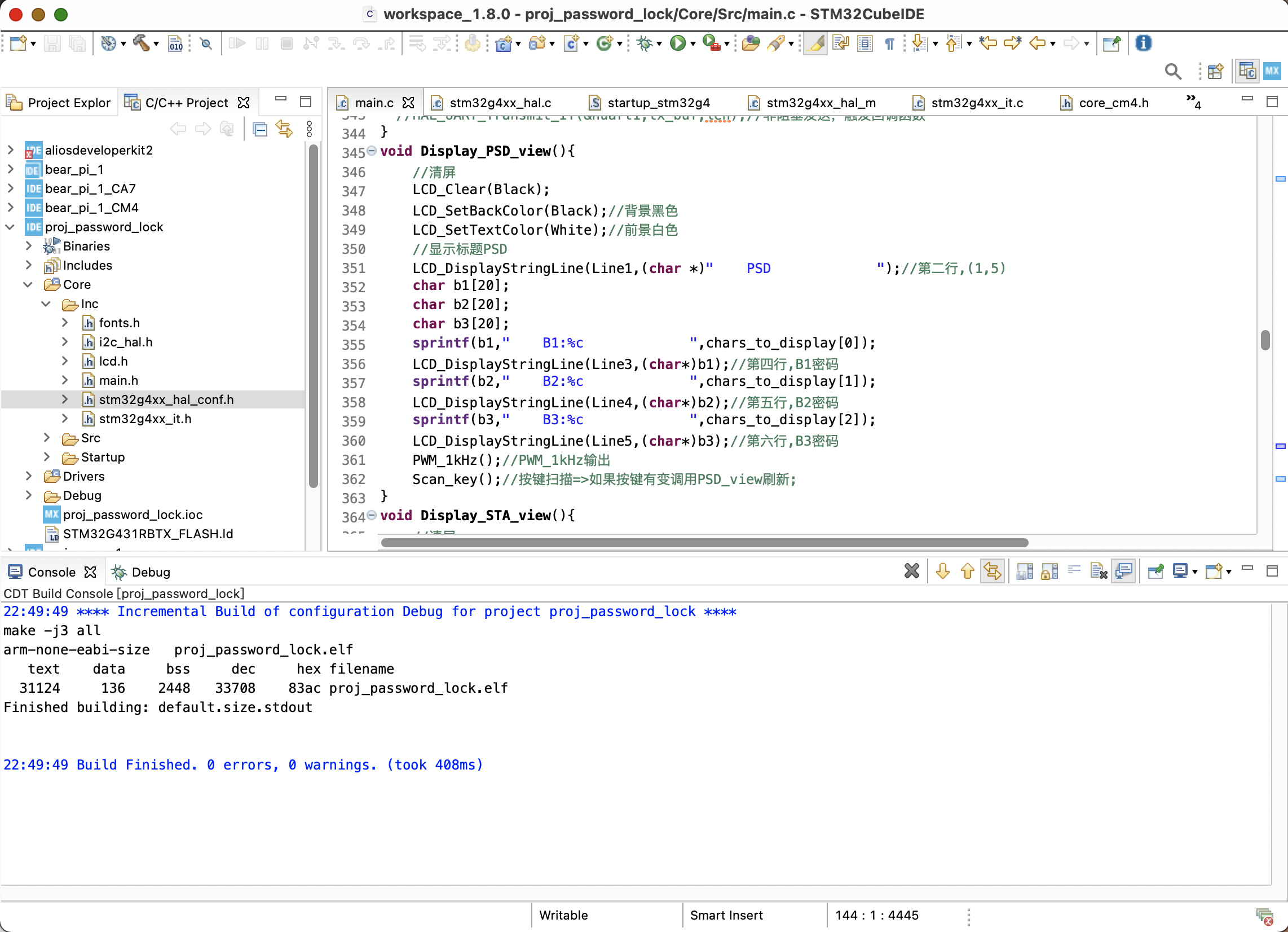
编译:
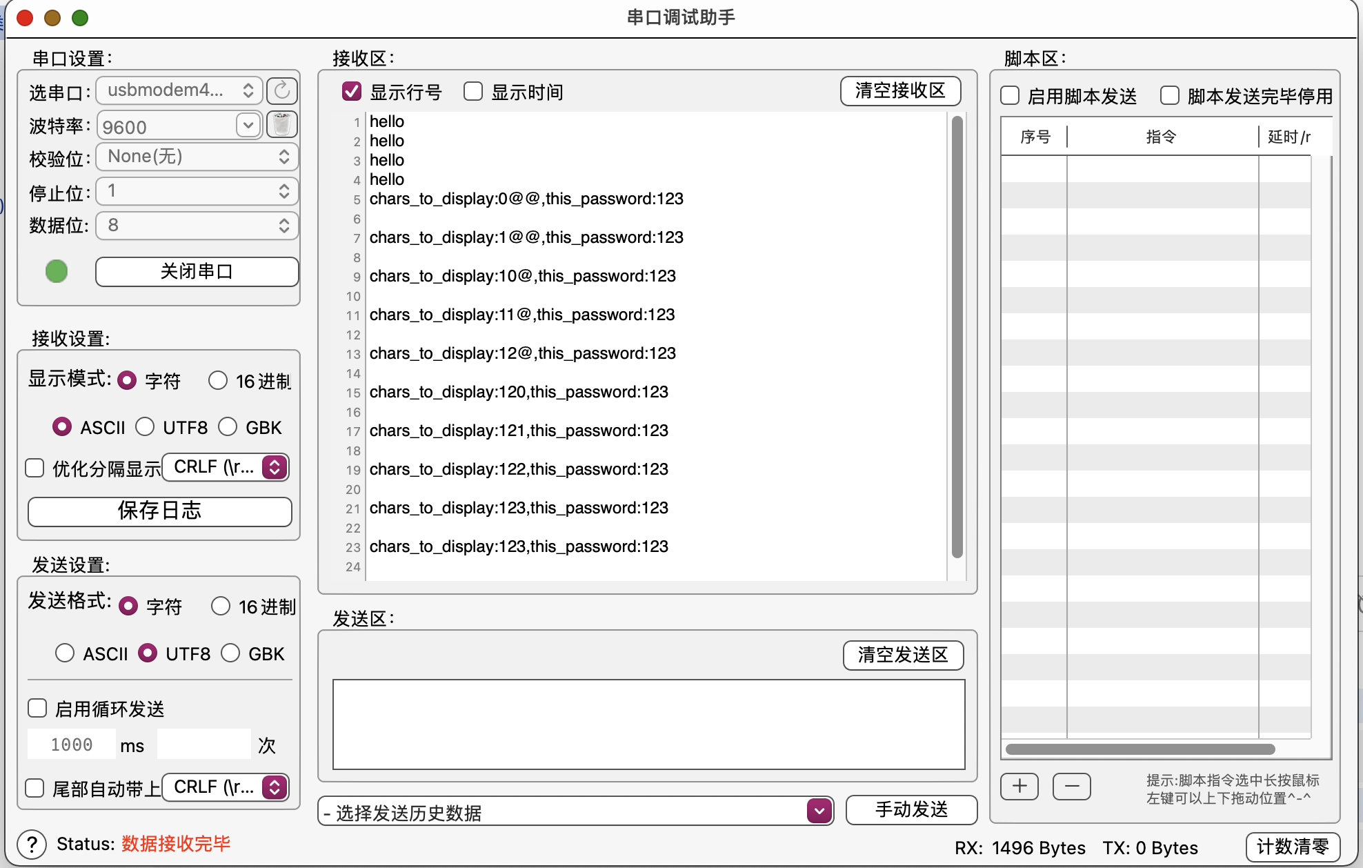
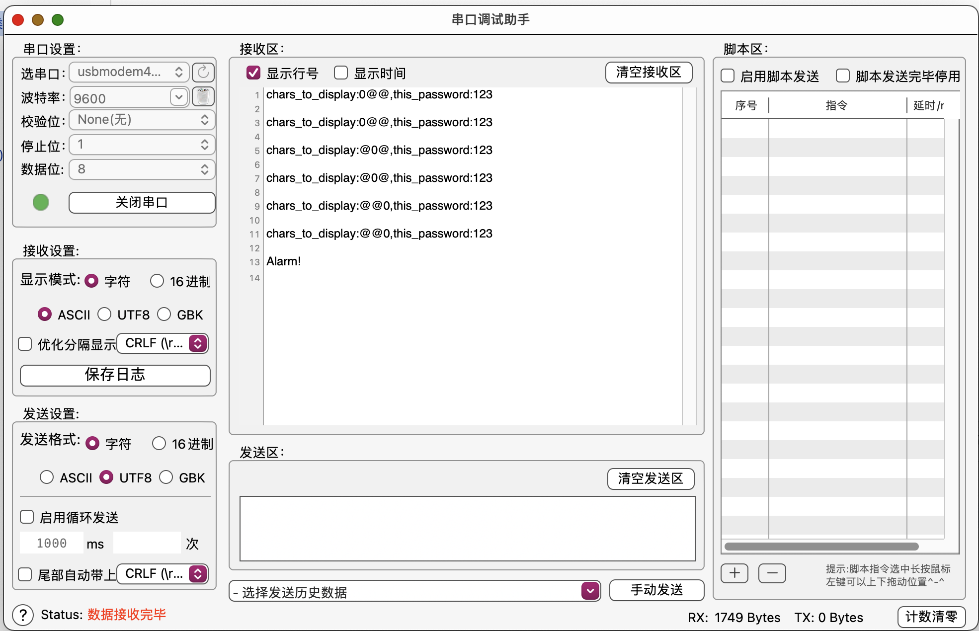
效果
附录
LCD驱动代码
注意:从KEIL转移到STM32CubeIDE时需要加上#define __nop() __NOP()。
lcd.c
/*
  程序说明: CT117E嵌入式竞赛板LCD驱动程序
  软件环境: Keil uVision 4.10
  硬件环境: CT117E嵌入式竞赛板
  日    期: 2011-8-9
*/
#include "lcd.h"
#include "fonts.h"
#define __nop() __NOP()
//#include "systick.h"
static  vu16 TextColor = 0x0000, BackColor = 0xFFFF;
vu16 dummy;

/*******************************************************************************
* Function Name  : Delay_LCD
* Description    : Inserts a delay time.
* Input          : nCount: specifies the delay time length.
* Output         : None
* Return         : None
*******************************************************************************/
void Delay_LCD(u16 n)
{
	u16 i,j;
	for (i = 0;i<n;++i)
		for(j=0;j<3000;++j);
}

/*
	uC8230型液晶控制器寄存器配置
*/
void REG_8230_Init(void)
{
	LCD_WriteReg(0x0000,0x0001);
	Delay_LCD(1000);
	LCD_WriteReg(0x0001,0x0000);
	LCD_WriteReg(0x0010,0x1790);
	LCD_WriteReg(0x0060,0x2700);
	LCD_WriteReg(0x0061,0x0001);
	LCD_WriteReg(0x0046,0x0002);
	LCD_WriteReg(0x0013,0x8010);
	LCD_WriteReg(0x0012,0x80fe);
	LCD_WriteReg(0x0002,0x0500);
	LCD_WriteReg(0x0003,0x1030);

	LCD_WriteReg(0x0030,0x0303);
	LCD_WriteReg(0x0031,0x0303);
	LCD_WriteReg(0x0032,0x0303);
	LCD_WriteReg(0x0033,0x0300);
	LCD_WriteReg(0x0034,0x0003);
	LCD_WriteReg(0x0035,0x0303);
	LCD_WriteReg(0x0036,0x0014);
	LCD_WriteReg(0x0037,0x0303);
	LCD_WriteReg(0x0038,0x0303);
	LCD_WriteReg(0x0039,0x0303);
	LCD_WriteReg(0x003a,0x0300);
	LCD_WriteReg(0x003b,0x0003);
	LCD_WriteReg(0x003c,0x0303);
	LCD_WriteReg(0x003d,0x1400);

	LCD_WriteReg(0x0092,0x0200);
	LCD_WriteReg(0x0093,0x0303);
	LCD_WriteReg(0x0090,0x080d);
	LCD_WriteReg(0x0003,0x1018);
	LCD_WriteReg(0x0007,0x0173);
}

void REG_932X_Init(void)
{
	LCD_WriteReg(R227, 0x3008);   // Set internal timing
	LCD_WriteReg(R231, 0x0012); // Set internal timing
	LCD_WriteReg(R239, 0x1231);   // Set internal timing
	LCD_WriteReg(R1  , 0x0000); // set SS and SM bit		  //0x0100
	LCD_WriteReg(R2  , 0x0700); // set 1 line inversion
	LCD_WriteReg(R3  , 0x1030);   // set GRAM write direction and BGR=1.
	LCD_WriteReg(R4  , 0x0000);   // Resize register
	LCD_WriteReg(R8  , 0x0207);   // set the back porch and front porch
	LCD_WriteReg(R9  , 0x0000);   // set non-display area refresh cycle ISC[3:0]
	LCD_WriteReg(R10 , 0x0000);   // FMARK function
	LCD_WriteReg(R12 , 0x0000); // RGB interface setting
	LCD_WriteReg(R13 , 0x0000);   // Frame marker Position
	LCD_WriteReg(R15 , 0x0000); // RGB interface polarity
	/**************Power On sequence ****************/
	LCD_WriteReg(R16 , 0x0000);   // SAP, BT[3:0], AP, DSTB, SLP, STB
	LCD_WriteReg(R17 , 0x0007);   // DC1[2:0], DC0[2:0], VC[2:0]
	LCD_WriteReg(R18 , 0x0000); // VREG1OUT voltage
	LCD_WriteReg(R19 , 0x0000);   // VDV[4:0] for VCOM amplitude
//	Delay_Ms(200);                    // Delay 200 MS , Dis-charge capacitor power voltage
	HAL_Delay(200);
	LCD_WriteReg(R16 , 0x1690);   // SAP, BT[3:0], AP, DSTB, SLP, STB
	LCD_WriteReg(R17 , 0x0227); // R11H=0x0221 at VCI=3.3V, DC1[2:0], DC0[2:0], VC[2:0]
//	Delay_Ms(50);      // Delay 50ms
	HAL_Delay(50);
	LCD_WriteReg(R18 , 0x001D); // External reference voltage= Vci;
//	Delay_Ms(50);      // Delay 50ms
	HAL_Delay(50);
	LCD_WriteReg(R19 , 0x0800); // R13H=1D00 when R12H=009D;VDV[4:0] for VCOM amplitude
	LCD_WriteReg(R41 , 0x0014); // R29H=0013 when R12H=009D;VCM[5:0] for VCOMH
	LCD_WriteReg(R43 , 0x000B);   // Frame Rate = 96Hz
//	Delay_Ms(50);      // Delay 50ms
	HAL_Delay(50);
	LCD_WriteReg(R32 , 0x0000); // GRAM horizontal Address
	LCD_WriteReg(R33 , 0x0000); // GRAM Vertical Address
	/* ----------- Adjust the Gamma Curve ---------- */
	LCD_WriteReg(R48 , 0x0007);
	LCD_WriteReg(R49 , 0x0707);
	LCD_WriteReg(R50 , 0x0006);
	LCD_WriteReg(R53 , 0x0704);
	LCD_WriteReg(R54 , 0x1F04);
	LCD_WriteReg(R55 , 0x0004);
	LCD_WriteReg(R56 , 0x0000);
	LCD_WriteReg(R57 , 0x0706);
	LCD_WriteReg(R60 , 0x0701);
	LCD_WriteReg(R61 , 0x000F);
	/* ------------------ Set GRAM area --------------- */
	LCD_WriteReg(R80 , 0x0000);   // Horizontal GRAM Start Address
	LCD_WriteReg(R81 , 0x00EF);   // Horizontal GRAM End Address
	LCD_WriteReg(R82 , 0x0000); // Vertical GRAM Start Address
	LCD_WriteReg(R83 , 0x013F); // Vertical GRAM Start Address
	LCD_WriteReg(R96 , 0x2700); // Gate Scan Line		  0xA700
	LCD_WriteReg(R97 , 0x0001); // NDL,VLE, REV
	LCD_WriteReg(R106, 0x0000); // set scrolling line
	/* -------------- Partial Display Control --------- */
	LCD_WriteReg(R128, 0x0000);
	LCD_WriteReg(R129, 0x0000);
	LCD_WriteReg(R130, 0x0000);
	LCD_WriteReg(R131, 0x0000);
	LCD_WriteReg(R132, 0x0000);
	LCD_WriteReg(R133, 0x0000);
	/* -------------- Panel Control ------------------- */
	LCD_WriteReg(R144, 0x0010);
	LCD_WriteReg(R146, 0x0000);
	LCD_WriteReg(R147, 0x0003);
	LCD_WriteReg(R149, 0x0110);
	LCD_WriteReg(R151, 0x0000);
	LCD_WriteReg(R152, 0x0000);
	   /* Set GRAM write direction and BGR = 1 */
	   /* I/D=01 (Horizontal : increment, Vertical : decrement) */
	   /* AM=1 (address is updated in vertical writing direction) */
	LCD_WriteReg(R3  , 0x01018);  //0x1018

	LCD_WriteReg(R7  , 0x0173); // 262K color and display ON
}
/*******************************************************************************
* Function Name  : STM3210B_LCD_Init
* Description    : Initializes the LCD.
* Input          : None
* Output         : None
* Return         : None
*******************************************************************************/
void LCD_Init(void)
{
	LCD_CtrlLinesConfig();
	dummy = LCD_ReadReg(0);

	if(dummy == 0x8230){
		REG_8230_Init();
	}
	else{
		REG_932X_Init();
	}
	dummy = LCD_ReadReg(0);

}
/*******************************************************************************
* Function Name  : LCD_SetTextColor
* Description    : Sets the Text color.
* Input          : - Color: specifies the Text color code RGB(5-6-5).
* Output         : - TextColor: Text color global variable used by LCD_DrawChar
*                  and LCD_DrawPicture functions.
* Return         : None
*******************************************************************************/
void LCD_SetTextColor(vu16 Color)
{
	TextColor = Color;
}
/*******************************************************************************
* Function Name  : LCD_SetBackColor
* Description    : Sets the Background color.
* Input          : - Color: specifies the Background color code RGB(5-6-5).
* Output         : - BackColor: Background color global variable used by
*                  LCD_DrawChar and LCD_DrawPicture functions.
* Return         : None
*******************************************************************************/
void LCD_SetBackColor(vu16 Color)
{
	BackColor = Color;
}
/*******************************************************************************
* Function Name  : LCD_ClearLine
* Description    : Clears the selected line.
* Input          : - Line: the Line to be cleared.
*                    This parameter can be one of the following values:
*                       - Linex: where x can be 0..9
* Output         : None
* Return         : None
*******************************************************************************/
void LCD_ClearLine(u8 Line)
{
	LCD_DisplayStringLine(Line, "                    ");
}
/*******************************************************************************
* Function Name  : LCD_Clear
* Description    : Clears the hole LCD.
* Input          : Color: the color of the background.
* Output         : None
* Return         : None
*******************************************************************************/
void LCD_Clear(u16 Color)
{
	u32 index = 0;
	LCD_SetCursor(0x00, 0x0000);
	LCD_WriteRAM_Prepare(); /* Prepare to write GRAM */
	for(index = 0; index < 76800; index++)
	{
		LCD_WriteRAM(Color);
	}
}
/*******************************************************************************
* Function Name  : LCD_SetCursor
* Description    : Sets the cursor position.
* Input          : - Xpos: specifies the X position.
*                  - Ypos: specifies the Y position.
* Output         : None
* Return         : None
*******************************************************************************/
void LCD_SetCursor(u8 Xpos, u16 Ypos)
{
	LCD_WriteReg(R32, Xpos);
	LCD_WriteReg(R33, Ypos);
}
/*******************************************************************************
* Function Name  : LCD_DrawChar
* Description    : Draws a character on LCD.
* Input          : - Xpos: the Line where to display the character shape.
*                    This parameter can be one of the following values:
*                       - Linex: where x can be 0..9
*                  - Ypos: start column address.
*                  - c: pointer to the character data.
* Output         : None
* Return         : None
*******************************************************************************/
void LCD_DrawChar(u8 Xpos, u16 Ypos, uc16 *c)
{
	u32 index = 0, i = 0;
	u8 Xaddress = 0;

	Xaddress = Xpos;
	LCD_SetCursor(Xaddress, Ypos);

	for(index = 0; index < 24; index++)
	{
		LCD_WriteRAM_Prepare(); /* Prepare to write GRAM */
		for(i = 0; i < 16; i++)
		{
			if((c[index] & (1 << i)) == 0x00)
			{
				LCD_WriteRAM(BackColor);
			}
			else
			{
				LCD_WriteRAM(TextColor);
			}
		}
		Xaddress++;
		LCD_SetCursor(Xaddress, Ypos);
	}
}
/*******************************************************************************
* Function Name  : LCD_DisplayChar
* Description    : Displays one character (16dots width, 24dots height).
* Input          : - Line: the Line where to display the character shape .
*                    This parameter can be one of the following values:
*                       - Linex: where x can be 0..9
*                  - Column: start column address.
*                  - Ascii: character ascii code, must be between 0x20 and 0x7E.
* Output         : None
* Return         : None
*******************************************************************************/
void LCD_DisplayChar(u8 Line, u16 Column, u8 Ascii)
{
	Ascii -= 32;
	LCD_DrawChar(Line, Column, &ASCII_Table[Ascii * 24]);
}
/*******************************************************************************
* Function Name  : LCD_DisplayStringLine
* Description    : Displays a maximum of 20 char on the LCD.
* Input          : - Line: the Line where to display the character shape .
*                    This parameter can be one of the following values:
*                       - Linex: where x can be 0..9
*                  - *ptr: pointer to string to display on LCD.
* Output         : None
* Return         : None
*******************************************************************************/
void LCD_DisplayStringLine(u8 Line, u8 *ptr)
{
	u32 i = 0;
	u16 refcolumn = 319;//319;

	while ((*ptr != 0) && (i < 20))	 //	20
	{
		LCD_DisplayChar(Line, refcolumn, *ptr);
		refcolumn -= 16;
		ptr++;
		i++;
	}
}
/*******************************************************************************
* Function Name  : LCD_SetDisplayWindow
* Description    : Sets a display window
* Input          : - Xpos: specifies the X buttom left position.
*                  - Ypos: specifies the Y buttom left position.
*                  - Height: display window height.
*                  - Width: display window width.
* Output         : None
* Return         : None
*******************************************************************************/
void LCD_SetDisplayWindow(u8 Xpos, u16 Ypos, u8 Height, u16 Width)
{
	if(Xpos >= Height)
	{
		LCD_WriteReg(R80, (Xpos - Height + 1));
	}
	else
	{
		LCD_WriteReg(R80, 0);
	}
	LCD_WriteReg(R81, Xpos);
	if(Ypos >= Width)
	{
		LCD_WriteReg(R82, (Ypos - Width + 1));
	}
	else
	{
		LCD_WriteReg(R82, 0);
	}
	/* Vertical GRAM End Address */
	LCD_WriteReg(R83, Ypos);
	LCD_SetCursor(Xpos, Ypos);
}
/*******************************************************************************
* Function Name  : LCD_WindowModeDisable
* Description    : Disables LCD Window mode.
* Input          : None
* Output         : None
* Return         : None
*******************************************************************************/
void LCD_WindowModeDisable(void)
{
	LCD_SetDisplayWindow(239, 0x13F, 240, 320);
	LCD_WriteReg(R3, 0x1018);
}
/*******************************************************************************
* Function Name  : LCD_DrawLine
* Description    : Displays a line.
* Input          : - Xpos: specifies the X position.
*                  - Ypos: specifies the Y position.
*                  - Length: line length.
*                  - Direction: line direction.
*                    This parameter can be one of the following values: Vertical
*                    or Horizontal.
* Output         : None
* Return         : None
*******************************************************************************/
void LCD_DrawLine(u8 Xpos, u16 Ypos, u16 Length, u8 Direction)
{
	u32 i = 0;

	LCD_SetCursor(Xpos, Ypos);
	if(Direction == Horizontal)
	{
		LCD_WriteRAM_Prepare(); /* Prepare to write GRAM */
		for(i = 0; i < Length; i++)
		{
			LCD_WriteRAM(TextColor);
		}
	}
	else
	{
		for(i = 0; i < Length; i++)
		{
			LCD_WriteRAM_Prepare(); /* Prepare to write GRAM */
			LCD_WriteRAM(TextColor);
			Xpos++;
			LCD_SetCursor(Xpos, Ypos);
		}
	}
}
/*******************************************************************************
* Function Name  : LCD_DrawRect
* Description    : Displays a rectangle.
* Input          : - Xpos: specifies the X position.
*                  - Ypos: specifies the Y position.
*                  - Height: display rectangle height.
*                  - Width: display rectangle width.
* Output         : None
* Return         : None
*******************************************************************************/
void LCD_DrawRect(u8 Xpos, u16 Ypos, u8 Height, u16 Width)
{
	LCD_DrawLine(Xpos, Ypos, Width, Horizontal);
	LCD_DrawLine((Xpos + Height), Ypos, Width, Horizontal);

	LCD_DrawLine(Xpos, Ypos, Height, Vertical);
	LCD_DrawLine(Xpos, (Ypos - Width + 1), Height, Vertical);
}
/*******************************************************************************
* Function Name  : LCD_DrawCircle
* Description    : Displays a circle.
* Input          : - Xpos: specifies the X position.
*                  - Ypos: specifies the Y position.
*                  - Height: display rectangle height.
*                  - Width: display rectangle width.
* Output         : None
* Return         : None
*******************************************************************************/
void LCD_DrawCircle(u8 Xpos, u16 Ypos, u16 Radius)
{
	s32  D;
	u32  CurX;
	u32  CurY;

  	D = 3 - (Radius << 1);
  	CurX = 0;
  	CurY = Radius;

  	while (CurX <= CurY)
  	{
	    LCD_SetCursor(Xpos + CurX, Ypos + CurY);
	    LCD_WriteRAM_Prepare(); /* Prepare to write GRAM */
	    LCD_WriteRAM(TextColor);

	    LCD_SetCursor(Xpos + CurX, Ypos - CurY);
	    LCD_WriteRAM_Prepare(); /* Prepare to write GRAM */
	    LCD_WriteRAM(TextColor);

	    LCD_SetCursor(Xpos - CurX, Ypos + CurY);
	    LCD_WriteRAM_Prepare(); /* Prepare to write GRAM */
	    LCD_WriteRAM(TextColor);

	    LCD_SetCursor(Xpos - CurX, Ypos - CurY);
	    LCD_WriteRAM_Prepare(); /* Prepare to write GRAM */
	    LCD_WriteRAM(TextColor);

	    LCD_SetCursor(Xpos + CurY, Ypos + CurX);
	    LCD_WriteRAM_Prepare(); /* Prepare to write GRAM */
	    LCD_WriteRAM(TextColor);

	    LCD_SetCursor(Xpos + CurY, Ypos - CurX);
	    LCD_WriteRAM_Prepare(); /* Prepare to write GRAM */
	    LCD_WriteRAM(TextColor);

	    LCD_SetCursor(Xpos - CurY, Ypos + CurX);
	    LCD_WriteRAM_Prepare(); /* Prepare to write GRAM */
	    LCD_WriteRAM(TextColor);

	    LCD_SetCursor(Xpos - CurY, Ypos - CurX);
	    LCD_WriteRAM_Prepare(); /* Prepare to write GRAM */
	    LCD_WriteRAM(TextColor);

	    if (D < 0)
	    {
	      D += (CurX << 2) + 6;
	    }
	    else
	    {
	      D += ((CurX - CurY) << 2) + 10;
	      CurY--;
	    }
	    CurX++;
  	}
}
/*******************************************************************************
* Function Name  : LCD_DrawMonoPict
* Description    : Displays a monocolor picture.
* Input          : - Pict: pointer to the picture array.
* Output         : None
* Return         : None
*******************************************************************************/
void LCD_DrawMonoPict(uc32 *Pict)
{
	u32 index = 0, i = 0;

	LCD_SetCursor(0, 319);

	LCD_WriteRAM_Prepare(); /* Prepare to write GRAM */
	for(index = 0; index < 2400; index++)
	{
		for(i = 0; i < 32; i++)
		{
			if((Pict[index] & (1 << i)) == 0x00)
			{
				LCD_WriteRAM(BackColor);
			}
			else
			{
				LCD_WriteRAM(TextColor);
			}
		}
	}
}
/*******************************************************************************
* Function Name  : LCD_WriteBMP
* Description    : Displays a bitmap picture loaded in the internal Flash.
* Input          : - BmpAddress: Bmp picture address in the internal Flash.
* Output         : None
* Return         : None
*******************************************************************************/
void LCD_WriteBMP(u32 BmpAddress)
{
	u32 index = 0, size = 0;

	size = *(vu16 *) (BmpAddress + 2);
	size |= (*(vu16 *) (BmpAddress + 4)) << 16;

	index = *(vu16 *) (BmpAddress + 10);
	index |= (*(vu16 *) (BmpAddress + 12)) << 16;
	size = (size - index)/2;
	BmpAddress += index;

	LCD_WriteReg(R3, 0x1008);
	LCD_WriteRAM_Prepare();
	for(index = 0; index < size; index++)
	{
		LCD_WriteRAM(*(vu16 *)BmpAddress);
		BmpAddress += 2;
	}
	LCD_WriteReg(R3, 0x1018);
}
/*******************************************************************************
* Function Name  : LCD_WriteReg
* Description    : Writes to the selected LCD register.
* Input          : - LCD_Reg: address of the selected register.
*                  - LCD_RegValue: value to write to the selected register.
* Output         : None
* Return         : None
*******************************************************************************/
void LCD_WriteReg(u8 LCD_Reg, u16 LCD_RegValue)
{
	GPIOB->BRR  |= GPIO_PIN_9;
	GPIOB->BRR  |= GPIO_PIN_8;
	GPIOB->BSRR |= GPIO_PIN_5;

	GPIOC->ODR = LCD_Reg;
	GPIOB->BRR  |= GPIO_PIN_5;
	__nop();
	__nop();
	__nop();
	GPIOB->BSRR |= GPIO_PIN_5;
	GPIOB->BSRR |= GPIO_PIN_8;

	GPIOC->ODR = LCD_RegValue;
	GPIOB->BRR  |= GPIO_PIN_5;
	__nop();
	__nop();
	__nop();
	GPIOB->BSRR |= GPIO_PIN_5;
	GPIOB->BSRR |= GPIO_PIN_8;
}
/*******************************************************************************
* Function Name  : LCD_ReadReg
* Description    : Reads the selected LCD Register.
* Input          : None
* Output         : None
* Return         : LCD Register Value.
*******************************************************************************/
u16 LCD_ReadReg(u8 LCD_Reg)
{
	u16 temp;

	GPIOB->BRR |= GPIO_PIN_9;
	GPIOB->BRR |= GPIO_PIN_8;
	GPIOB->BSRR |= GPIO_PIN_5;

	GPIOC->ODR = LCD_Reg;
	GPIOB->BRR |= GPIO_PIN_5;
	__nop();
	__nop();
	__nop();
	GPIOB->BSRR |= GPIO_PIN_5;
	GPIOB->BSRR |= GPIO_PIN_8;

	LCD_BusIn();
	GPIOA->BRR |= GPIO_PIN_8;
	__nop();
	__nop();
	__nop();
	temp = GPIOC->IDR;
	GPIOA->BSRR |= GPIO_PIN_8;

	LCD_BusOut();
	GPIOB->BSRR |= GPIO_PIN_9;

	return temp;
}
/*******************************************************************************
* Function Name  : LCD_WriteRAM_Prepare
* Description    : Prepare to write to the LCD RAM.
* Input          : None
* Output         : None
* Return         : None
*******************************************************************************/
void LCD_WriteRAM_Prepare(void)
{
	GPIOB->BRR  |=  GPIO_PIN_9;
	GPIOB->BRR  |=  GPIO_PIN_8;
	GPIOB->BSRR |=  GPIO_PIN_5;

	GPIOC->ODR = R34;
	GPIOB->BRR  |=  GPIO_PIN_5;
	__nop();
	__nop();
	__nop();
	GPIOB->BSRR |=  GPIO_PIN_5;
	GPIOB->BSRR |=  GPIO_PIN_8;
	__nop();
	__nop();
	__nop();
	GPIOB->BSRR |=  GPIO_PIN_9;
}
/*******************************************************************************
* Function Name  : LCD_WriteRAM
* Description    : Writes to the LCD RAM.
* Input          : - RGB_Code: the pixel color in RGB mode (5-6-5).
* Output         : None
* Return         : None
*******************************************************************************/
void LCD_WriteRAM(u16 RGB_Code)
{
	GPIOB->BRR  |=  GPIO_PIN_9;
	GPIOB->BSRR |=  GPIO_PIN_8;
	GPIOB->BSRR |=  GPIO_PIN_5;

	GPIOC->ODR = RGB_Code;
	GPIOB->BRR  |=  GPIO_PIN_5;
	__nop();
	__nop();
	__nop();
	GPIOB->BSRR |=  GPIO_PIN_5;
	GPIOB->BSRR |=  GPIO_PIN_8;
	__nop();
	__nop();
	__nop();
	GPIOB->BSRR |=  GPIO_PIN_9;
}
/*******************************************************************************
* Function Name  : LCD_ReadRAM
* Description    : Reads the LCD RAM.
* Input          : None
* Output         : None
* Return         : LCD RAM Value.
*******************************************************************************/
u16 LCD_ReadRAM(void)
{
	u16 temp;

	GPIOB->BRR  |=  GPIO_PIN_9;
	GPIOB->BRR  |=  GPIO_PIN_8;
	GPIOB->BSRR |=  GPIO_PIN_5;

	GPIOC->ODR = R34;
	GPIOB->BRR  |=  GPIO_PIN_5;
	__nop();
	__nop();
	__nop();
	GPIOB->BSRR |=  GPIO_PIN_5;
	GPIOB->BSRR |=  GPIO_PIN_8;

	LCD_BusIn();
	GPIOA->BRR |=  GPIO_PIN_8;
	__nop();
	__nop();
	__nop();
	temp = GPIOC->IDR;
	GPIOA->BSRR |=  GPIO_PIN_8;

	LCD_BusOut();
	GPIOB->BSRR |=  GPIO_PIN_9;

	return temp;
}
/*******************************************************************************
* Function Name  : LCD_PowerOn
* Description    : Power on the LCD.
* Input          : None
* Output         : None
* Return         : None
*******************************************************************************/
void LCD_PowerOn(void)
{
	LCD_WriteReg(R16, 0x0000);
	LCD_WriteReg(R17, 0x0000);
	LCD_WriteReg(R18, 0x0000);
	LCD_WriteReg(R19, 0x0000);
	Delay_LCD(20);
	LCD_WriteReg(R16, 0x17B0);
	LCD_WriteReg(R17, 0x0137);
	Delay_LCD(5);
	LCD_WriteReg(R18, 0x0139);
	Delay_LCD(5);
	LCD_WriteReg(R19, 0x1d00);
	LCD_WriteReg(R41, 0x0013);
	Delay_LCD(5);
	LCD_WriteReg(R7, 0x0173);
}
/*******************************************************************************
* Function Name  : LCD_DisplayOn
* Description    : Enables the Display.
* Input          : None
* Output         : None
* Return         : None
*******************************************************************************/
void LCD_DisplayOn(void)
{
	LCD_WriteReg(R7, 0x0173);
}
/*******************************************************************************
* Function Name  : LCD_DisplayOff
* Description    : Disables the Display.
* Input          : None
* Output         : None
* Return         : None
*******************************************************************************/
void LCD_DisplayOff(void)
{
	LCD_WriteReg(R7, 0x0);
}
/*******************************************************************************
* Function Name  : LCD_CtrlLinesConfig
* Description    : Configures LCD Control lines.
                   Push-Pull mode.
* Input          : None
* Output         : None
* Return         : None
*******************************************************************************/
void LCD_CtrlLinesConfig(void)
{
	GPIO_InitTypeDef GPIO_InitStruct = {0};

  __HAL_RCC_GPIOC_CLK_ENABLE();
  __HAL_RCC_GPIOA_CLK_ENABLE();
  __HAL_RCC_GPIOB_CLK_ENABLE();

	GPIO_InitStruct.Pin = GPIO_PIN_5 | GPIO_PIN_8 | GPIO_PIN_9;
	GPIO_InitStruct.Mode = GPIO_MODE_OUTPUT_PP;
  GPIO_InitStruct.Speed = GPIO_SPEED_FREQ_LOW;
  GPIO_InitStruct.Pull = GPIO_NOPULL;
  HAL_GPIO_Init(GPIOB, &GPIO_InitStruct);

	GPIO_InitStruct.Pin =  GPIO_PIN_8 ;
	GPIO_InitStruct.Mode = GPIO_MODE_OUTPUT_PP;
  GPIO_InitStruct.Speed = GPIO_SPEED_FREQ_LOW;
  GPIO_InitStruct.Pull = GPIO_NOPULL;
  HAL_GPIO_Init(GPIOA, &GPIO_InitStruct);

	LCD_BusOut();

	GPIOA->BSRR |= 0x0100;
	GPIOB->BSRR |= 0x0220;
}

/*******************************************************************************
* Function Name  : LCD_BusIn
* Description    : Configures the Parallel interface for LCD(PortC)
* Input          : None
* Output         : None
* Return         : None
*******************************************************************************/
void LCD_BusIn(void)
{
	GPIO_InitTypeDef GPIO_InitStruct = {0};

	GPIO_InitStruct.Pin = GPIO_PIN_All;
  GPIO_InitStruct.Mode = GPIO_MODE_INPUT;
  GPIO_InitStruct.Speed = GPIO_SPEED_FREQ_VERY_HIGH;
  GPIO_InitStruct.Pull = GPIO_NOPULL;
  HAL_GPIO_Init(GPIOC, &GPIO_InitStruct);
}

/*******************************************************************************
* Function Name  : LCD_BusOut
* Description    : Configures the Parallel interface for LCD(PortC)
* Input          : None
* Output         : None
* Return         : None
*******************************************************************************/
void LCD_BusOut(void)
{
	GPIO_InitTypeDef GPIO_InitStruct = {0};

	GPIO_InitStruct.Pin = GPIO_PIN_All;
  GPIO_InitStruct.Mode = GPIO_MODE_OUTPUT_PP;
  GPIO_InitStruct.Speed = GPIO_SPEED_FREQ_VERY_HIGH;
  GPIO_InitStruct.Pull = GPIO_NOPULL;
  HAL_GPIO_Init(GPIOC, &GPIO_InitStruct);
}

/*******************************************************************************
* Function Name  : LCD_DrawPicture
* Description    : Displays a 16 color picture.
* Input          : - picture: pointer to the picture array.
* Output         : None
* Return         : None
*******************************************************************************/
void LCD_DrawPicture(const u8* picture)
{
	int index;
	LCD_SetCursor(0x00, 0x0000);

	LCD_WriteRAM_Prepare(); /* Prepare to write GRAM */

	for(index = 0; index < 76800; index++)
	{
		LCD_WriteRAM(picture[2*index+1]<<8|picture[2*index]);
	}
}
lcd.h
/*
  程序说明: CT117E嵌入式竞赛板LCD驱动程序
  软件环境: Keil uVision 4.10
  硬件环境: CT117E嵌入式竞赛板
  日    期: 2011-8-9
*/
/* Define to prevent recursive inclusion -------------------------------------*/
#ifndef __LCD_H
#define __LCD_H

/* Includes ------------------------------------------------------------------*/
#include "main.h"
/* Exported types ------------------------------------------------------------*/
/* Exported constants --------------------------------------------------------*/
/* LCD Registers */
#define R0             0x00
#define R1             0x01
#define R2             0x02
#define R3             0x03
#define R4             0x04
#define R5             0x05
#define R6             0x06
#define R7             0x07
#define R8             0x08
#define R9             0x09
#define R10            0x0A
#define R12            0x0C
#define R13            0x0D
#define R14            0x0E
#define R15            0x0F
#define R16            0x10
#define R17            0x11
#define R18            0x12
#define R19            0x13
#define R20            0x14
#define R21            0x15
#define R22            0x16
#define R23            0x17
#define R24            0x18
#define R25            0x19
#define R26            0x1A
#define R27            0x1B
#define R28            0x1C
#define R29            0x1D
#define R30            0x1E
#define R31            0x1F
#define R32            0x20
#define R33            0x21
#define R34            0x22
#define R36            0x24
#define R37            0x25
#define R40            0x28
#define R41            0x29
#define R43            0x2B
#define R45            0x2D
#define R48            0x30
#define R49            0x31
#define R50            0x32
#define R51            0x33
#define R52            0x34
#define R53            0x35
#define R54            0x36
#define R55            0x37
#define R56            0x38
#define R57            0x39
#define R59            0x3B
#define R60            0x3C
#define R61            0x3D
#define R62            0x3E
#define R63            0x3F
#define R64            0x40
#define R65            0x41
#define R66            0x42
#define R67            0x43
#define R68            0x44
#define R69            0x45
#define R70            0x46
#define R71            0x47
#define R72            0x48
#define R73            0x49
#define R74            0x4A
#define R75            0x4B
#define R76            0x4C
#define R77            0x4D
#define R78            0x4E
#define R79            0x4F
#define R80            0x50
#define R81            0x51
#define R82            0x52
#define R83            0x53
#define R96            0x60
#define R97            0x61
#define R106           0x6A
#define R118           0x76
#define R128           0x80
#define R129           0x81
#define R130           0x82
#define R131           0x83
#define R132           0x84
#define R133           0x85
#define R134           0x86
#define R135           0x87
#define R136           0x88
#define R137           0x89
#define R139           0x8B
#define R140           0x8C
#define R141           0x8D
#define R143           0x8F
#define R144           0x90
#define R145           0x91
#define R146           0x92
#define R147           0x93
#define R148           0x94
#define R149           0x95
#define R150           0x96
#define R151           0x97
#define R152           0x98
#define R153           0x99
#define R154           0x9A
#define R157           0x9D
#define R192           0xC0
#define R193           0xC1
#define R227           0xE3
#define R229           0xE5
#define R231           0xE7
#define R239           0xEF

/* LCD Control pins */
//#define CtrlPin_NCS    GPIO_Pin_9   /* PB.9 */
//#define CtrlPin_RS     GPIO_Pin_8   /* PB.8 */
//#define CtrlPin_NWR    GPIO_Pin_5  /* Pb.5 */
//#define CtrlPin_NRD    GPIO_Pin_10  /* Pb.10 */

/* LCD color */
#define White          0xFFFF
#define Black          0x0000
#define Grey           0xF7DE
#define Blue           0x001F
#define Blue2          0x051F
#define Red            0xF800
#define Magenta        0xF81F
#define Green          0x07E0
#define Cyan           0x7FFF
#define Yellow         0xFFE0

#define Line0          0
#define Line1          24
#define Line2          48
#define Line3          72
#define Line4          96
#define Line5          120
#define Line6          144
#define Line7          168
#define Line8          192
#define Line9          216

#define Horizontal     0x00
#define Vertical       0x01


/* Exported macro ------------------------------------------------------------*/
/* Exported functions ------------------------------------------------------- */
/*----- High layer function -----*/
typedef int32_t  s32;
typedef int16_t s16;
typedef int8_t  s8;
typedef __IO uint32_t  vu32;
typedef __IO uint16_t vu16;
typedef __IO uint8_t  vu8;
typedef uint32_t  u32;
typedef uint16_t u16;
typedef uint8_t  u8;
typedef const uint32_t uc32;  /*!< Read Only */
typedef const uint16_t uc16;  /*!< Read Only */
typedef const uint8_t uc8;   /*!< Read Only */


void LCD_Init(void);
void LCD_SetTextColor(vu16 Color);
void LCD_SetBackColor(vu16 Color);
void LCD_ClearLine(u8 Line);
void LCD_Clear(u16 Color);
void LCD_SetCursor(u8 Xpos, u16 Ypos);
void LCD_DrawChar(u8 Xpos, u16 Ypos, uc16 *c);
void LCD_DisplayChar(u8 Line, u16 Column, u8 Ascii);
void LCD_DisplayStringLine(u8 Line, u8 *ptr);
void LCD_SetDisplayWindow(u8 Xpos, u16 Ypos, u8 Height, u16 Width);
void LCD_WindowModeDisable(void);
void LCD_DrawLine(u8 Xpos, u16 Ypos, u16 Length, u8 Direction);
void LCD_DrawRect(u8 Xpos, u16 Ypos, u8 Height, u16 Width);
void LCD_DrawCircle(u8 Xpos, u16 Ypos, u16 Radius);
void LCD_DrawMonoPict(uc32 *Pict);
void LCD_WriteBMP(u32 BmpAddress);
void LCD_DrawBMP(u32 BmpAddress);
void LCD_DrawPicture(const u8* picture);

/*----- Medium layer function -----*/
void LCD_WriteReg(u8 LCD_Reg, u16 LCD_RegValue);
u16 LCD_ReadReg(u8 LCD_Reg);
void LCD_WriteRAM_Prepare(void);
void LCD_WriteRAM(u16 RGB_Code);
u16 LCD_ReadRAM(void);
void LCD_PowerOn(void);
void LCD_DisplayOn(void);
void LCD_DisplayOff(void);

/*----- Low layer function -----*/
void LCD_CtrlLinesConfig(void);

void LCD_BusIn(void);
void LCD_BusOut(void);


#endif /* __LCD_H */

/******************* (C) COPYRIGHT 2008 STMicroelectronics *****END OF FILE****/
第十三届蓝桥嵌入式真题(省赛)

 浙公网安备 33010602011771号