27. USART, Universal synchronous asynchronous receiver transmitter
27.1 USART introduction
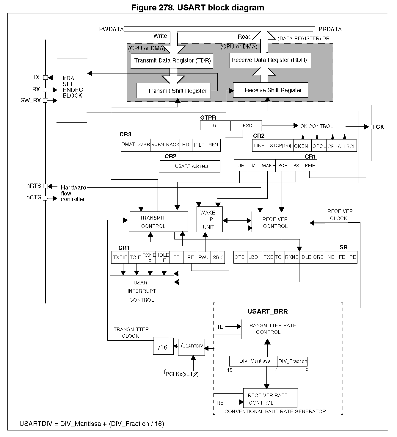
通用同步异步接收发射机(USART)对需要NRZ异步串行数据格式行业标准的外部设备,提供了一个灵活的全双工数据交换的方法。USART使用分数波特率生成器提供非常广泛的波特率。
它支持同步单向通信和半双工单线通信.它还支持LIN(本地互连网络)、SmartCard协议和IRDA(红外数据关联)SIR ENDEC规范和调制解调器操作(CTS/RTS)。它允许多处理器通信。
采用DMA进行多缓冲配置,可以实现高速数据通信。
说明:现在仅补充需要且用的内容,没有使用的内容虚位以待。
27.3 USART functional description


overrun error
RXNE标志是在每个字节接收后被置位的。如果在接收到下一个数据时置位了RXNE标志,或者之前的DMA请求未被服务,则会发生溢出错误。
当发生溢出错误时:
- ORE置位。
- RDR内容不会丢失。当执行对USART_DR的读取时,可以获得先前的数据。
- shift register 将被覆盖。在此之后,在溢出期间收到的任何数据都会丢失。
- 如果设置了RXNEIE位或同时设置了EIE和DMAR位,则会生成中断。
ORE位清零:先读取USART_SR寄存器,然后读取USART_DR寄存器。
Framing error
在下列情况下检测到帧错误:在去同步或过度噪声之后,在预期时间点无法被识别停止位。
当检测到帧错误时:
- The FE bit is set by hardware
- The invalid data is transferred from the Shift register to the USART_DR register.
- 在单字节通信情况下不产生中断。但是,此位(FE )与RXNE位同时上升,RXNE位本身生成一个中断。如果在USART_CR3寄存器中设置EIE位,则在多缓冲区通信时将发出中断。
FE 位清零:先读取USART_SR寄存器,然后读取USART_DR寄存器。
27.3.6 Multiprocessor communication
有可能与USART(一个网络中连接的几个USART)执行多处理器通信。例如,一个USART可以是主程序,它的TX输出连接到另一个USART的RX输入。其余的是从级输出,它们各自的TX输出逻辑地连接在一起,并连接到主服务器的RX输入。
在多处理器配置中,通常希望只有预期的消息接收方主动接收完整的消息内容,从而减少所有非地址接收器的冗余USART服务开销。
此处略……
27.3.7 Parity control

所以,当8bit通信使用奇偶校验位时,M应该置位,也就是使用9bit字长。
27.3.8 LIN (local interconnection network) mode
此处略……
27.3.9 USART synchronous mode
此处略……
27.3.10 Single-wire half-duplex communication
通过在USART_CR 3寄存器中设置HDSEL位来选择单线半双工模式。在这种模式下,必须清除下列比特:
- LINEN and CLKEN bits in the USART_CR2 register,
- SCEN and IREN bits in the USART_CR3 register.
USART可以配置为采用单线半双工协议。在单线半双工模式下,TX和RX引脚内部连接.半双工通信和全双工通信之间的选择是使用控制位‘HALF DUPLEX SEL’(在USART_CR 3中的HDSEL)进行的。
一旦 HDSEL 写到1:
- RX不再使用,
- 当没有传输数据时,总是释放TX。因此,它在空闲或接收时充当标准IO。这意味着IO必须配置,以便TX在不受USART驱动时被配置为浮动输入(或输出高开漏)。
除此之外,这些通信方式与在一般USART模式下所做的类似。线路上的冲突必须由软件来管理(例如,通过使用集中仲裁器)。
需要注意的是,当TE置位时,只要往数据寄存器里写入数据时硬件就不能阻断数据的传输。
27.3.11 Smartcard
此处略……
27.3.12 IrDA SIR ENDEC block
27.3.13 Continuous communication using DMA
USART能够使用DMA继续通信。对Rx缓冲区和TX缓冲区的DMA请求是独立生成的。
Transmission using DMA
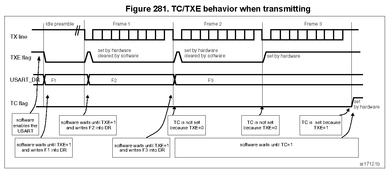
通过在USART_CR3寄存器中设置DMAT位,可以启用DMA模式进行传输。每当TXE置位时,数据就从使用DMA通道配置的SRAM区域(对应peripheral地址)加载到USART_DR寄存器。要为USART传输映射DMA信道,请使用以下过程(x表示信道号):
- 在DMA控制寄存器中写入USART_DR寄存器地址,将其配置为传输的目的地。数据将在每次TXE事件发生后从内存中移到此地址。
- 在DMA控制寄存器中写入内存地址,将其配置为传输源。在每个TXE事件后,这些数据将从这个内存区域中加载到USART_DR寄存器中。
- 配置要传输到DMA控制寄存器的字节总数。
- 在DMA寄存器中配置信道优先级
- 根据应用程序的要求,在一半/全部传输后配置DMA中断生成。
- Clear the TC bit in the SR register by writing 0 to it.
- Activate the channel in the DMA register.
当到达DMA控制器中编程的数据传输数时,DMA控制器在DMA通道中断向量上产生中断。

Reception using DMA
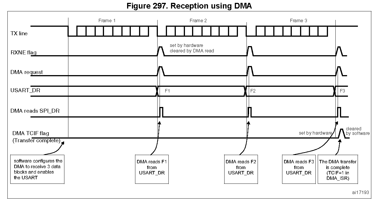
DMA mode can be enabled for reception by setting the DMAR bit in USART_CR3 register. Data is loaded from the USART_DR register to a SRAM area configured using the DMA peripheral (refer to the DMA specification) whenever a data byte is received.
To map a DMA channel for USART reception, use the following procedure:
- Write the USART_DR register address in the DMA control register to configure it as the source of the transfer. The data will be moved from this address to the memory after each RXNE event.
-
Write the memory address in the DMA control register to configure it as the destination of the transfer. The data will be loaded from USART_DR to this memory area after each RXNE event.
-
Configure the total number of bytes to be transferred in the DMA control register. - Configure the channel priority in the DMA control register
- Configure interrupt generation after half/ full transfer as required by the application.
- Activate the channel in the DMA control register.
When the number of data transfers programmed in the DMA Controller is reached, the DMA controller generates an interrupt on the DMA channel interrupt vector.

remapping


