Quartus 入门 —— FPGA 超声波测距(HC-SR04)
Quartus 入门 —— FPGA 超声波测距(HC-SR04)
这里我们跳过项目创建以及代码导入的过程,直接介绍项目核心内容的设计
模块设计
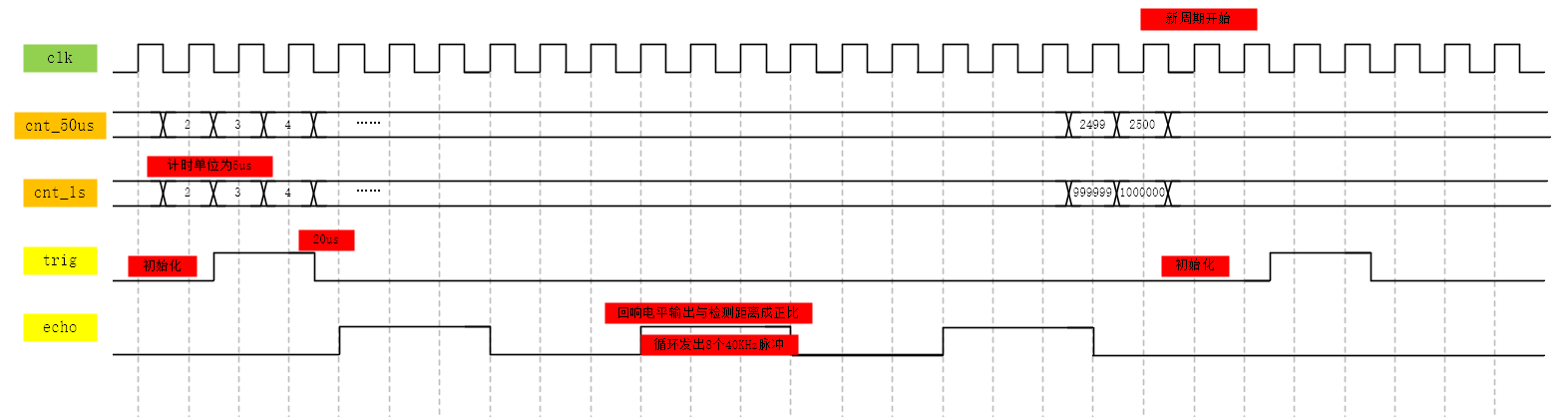
根据波形本项目总共分为五个模块:
- clk_div:计时模块:通过计时给出需要输出电平、数吗管段选位移或进行数据处理的信号
这里只需要设计 1MHz 的时钟即可:
	parameter CNT_MAX = 19'd49;//1us的计数值为 50 * Tclk(20ns)

	reg		[5:0]	cnt		;
	wire			add_cnt ;
	wire			end_cnt ;
	always @(posedge clk or negedge rstn) begin
		if(!rstn) begin
			cnt <= 6'd0;
		end
		else if(cnt == CNT_MAX) begin
			cnt <= 6'd0;
		end
		else begin
			cnt <= cnt + 6'd1;
		end
	end

	assign clk_us = cnt >= CNT_MAX ;
- trig_driver:主要负责控制 10μS 持续电平输出,按照系统设计,平均每 1s 先等待 10μS,信号稳定后输出 10μS 持续电平
这里主要进行判断,判断trig何时需要输出,根据时序图判断,只有在 1MHz 时钟下,平均每 100μS 输出10μS 高电平,就可以驱动超声波
	always @(posedge clk_us or negedge rstn) begin
		if(!rstn) begin
			cnt <= 19'd0;
		end
		else if(cnt == CYCLE_MAX) begin
			cnt <= 19'd0;
		end
		else begin
			cnt <= cnt + 19'd1;
		end
	end

	assign trig = cnt < 15 ? 1'b1 : 1'b0;
- echo_triger:输入信号处理,回响电平输出与检测距离正比,通过计算输出距离数据
首先我们需要进行边缘检测,检测上升沿和下降沿:
	parameter T_MAX = 16'd60_000;//510cm 对应计数值
	reg				r1_echo,r2_echo; //边沿检测
	wire			echo_pos,echo_neg; //
	//如果使用clk_us 检测边沿,延时2us,差值过大
	always @(posedge clk or negedge rstn)begin
		if(!rstn)begin
			r1_echo <= 1'b0;
			r2_echo <= 1'b0;
		end
		else begin
			r1_echo <= echo;
			r2_echo <= r1_echo;
		end
	end

	assign echo_pos = r1_echo & ~r2_echo;
	assign echo_neg = ~r1_echo & r2_echo;
然后我们需要对收到的距离信息进行处理,得出我们想要的数据,这里我们通过将数据 *1000 来处理小数
	always @(posedge clk or negedge rstn)begin
		if(!rstn)begin
			data_r <= 'd2;
		end
		else if(echo_neg)begin
			data_r <= (cnt << 4) + cnt;
		end
		else begin
			data_r <= data_r;
		end
	end

	assign data_o = data_r >> 1;
- seg_driver:计算得到数码管需要输出的内容并实时显示
计算每一位的输出数据:
	always @(posedge clk or negedge rstn)begin
		if(!rstn)begin
			cm_hund	<= 'd0;
			cm_ten	<= 'd0;
			cm_unit	<= 'd0;
			point_1	<= 'd0;
			point_2	<= 'd0;
			point_3	<= 'd0;
		end
		else begin
			cm_hund <= data_in / 10 ** 5;
			cm_ten	<= data_in / 10 ** 4 % 10;
			cm_unit <= data_in / 10 ** 3 % 10;
			point_1 <= data_in / 10 ** 2 % 10;
			point_2 <= data_in / 10 ** 1 % 10;
			point_3 <= data_in / 10 ** 0 % 10;
		end
	end
这里我们通过函数判断输出的数据:
    // 函数,4位输入,7位输出,判断要输出的数字
    function  [7:0]	hex_data; //函数不含时序逻辑相关
		input   [03:00]	data_i;//至少一个输入
		begin
			case(data_i)
				4'd0:hex_data = NUM_0;
				4'd1:hex_data = NUM_1;
				4'd2:hex_data = NUM_2;
				4'd3:hex_data = NUM_3;
				4'd4:hex_data = NUM_4;
				4'd5:hex_data = NUM_5;
				4'd6:hex_data = NUM_6;
				4'd7:hex_data = NUM_7;
				4'd8:hex_data = NUM_8;
				4'd9:hex_data = NUM_9;
				default:hex_data = ALL_LIGHT;
			endcase
		end
	endfunction
- HC_SR04_TOP:将上述模块连接起来,作为系统的顶层模块
代码设计
clk_div.v:
module 	clk_div(
	input  wire			clk		,
	input  wire 		rstn	,

	output wire  		clk_us 	  //
);

	parameter CNT_MAX = 19'd49;//1us的计数值为 50 * Tclk(20ns)

	reg		[5:0]	cnt		;
	wire			add_cnt ;
	wire			end_cnt ;

	// 时钟分频
	always @(posedge clk or negedge rstn) begin
		if(!rstn) begin
			cnt <= 6'd0;
		end
		else if(cnt == CNT_MAX) begin
			cnt <= 6'd0;
		end
		else begin
			cnt <= cnt + 6'd1;
		end
	end

	assign clk_us = cnt >= CNT_MAX ;


endmodule
trig_driver.v:
module 	trig_driver(
	input  wire			clk_us	,
	input  wire 		rstn	,

	output wire  		trig	  //触发测距信号
);

	parameter CYCLE_MAX = 19'd29_9999;

	reg		[18:00]	cnt		;

// 10毫秒持续电平输出

	always @(posedge clk_us or negedge rstn) begin
		if(!rstn) begin
			cnt <= 19'd0;
		end
		else if(cnt == CYCLE_MAX) begin
			cnt <= 19'd0;
		end
		else begin
			cnt <= cnt + 19'd1;
		end
	end

	assign trig = cnt < 15 ? 1'b1 : 1'b0;

endmodule
echo_triger.v:
module 	echo_driver(
	input  wire 		clk		,
	input  wire			clk_us	,
	input  wire 		rstn	,

	input  wire 		echo	,
	output wire [18:00]	data_o	  //检测距离,保留3位小数,*1000实现
);

	parameter T_MAX = 16'd5_9999;//510cm 对应计数值

	reg				r1_echo,r2_echo; //边沿检测
	wire			echo_pos,echo_neg;

	reg		[15:00]	cnt		;

	reg		[18:00]	data_r	;

	//如果使用clk_us 检测边沿,延时2us,差值过大
	always @(posedge clk or negedge rstn)begin
		if(!rstn)begin
			r1_echo <= 1'b0;
			r2_echo <= 1'b0;
		end
		else begin
			r1_echo <= echo;
			r2_echo <= r1_echo;
		end
	end

	assign echo_pos = r1_echo & ~r2_echo;
	assign echo_neg = ~r1_echo & r2_echo;

	always @(posedge clk_us or negedge rstn) begin
		if(!rstn) begin
			cnt <= 16'd0;
		end
		else if(echo) begin
			if(cnt == T_MAX) begin
				cnt <= 16'd0;
			end
			else begin
				cnt <= cnt + 16'd1;
			end
		end
		else begin
			cnt <= 16'd0;
		end
	end

	always @(posedge clk or negedge rstn)begin
		if(!rstn)begin
			data_r <= 'd2;
		end
		else if(echo_neg)begin
			data_r <= (cnt << 4) + cnt;
		end
		else begin
			data_r <= data_r;
		end
	end

	assign data_o = data_r >> 1;

endmodule
seg_driver.v:
module seg_driver(
	input	wire		clk		,
	input	wire		rstn	,

	input	wire [18:0]	data_in	, //待显示数据

    output  reg [7:0]   sel     ,	// 我这里是8位段选,可以换6位,但是要自己改代码
    output  reg [7:0]   seg
);
 	//parameter define
	localparam	NUM_0	=	8'b1100_0000,
				NUM_1 	= 	8'b1111_1001,
				NUM_2   = 	8'b1010_0100,
				NUM_3   = 	8'b1011_0000,
				NUM_4   = 	8'b1001_1001,
				NUM_5   = 	8'b1001_0010,
				NUM_6   = 	8'b1000_0010,
				NUM_7   = 	8'b1111_1000,
				NUM_8   = 	8'b1000_0000,
				NUM_9   = 	8'b1001_0000,
				NUM_A   = 	8'b1000_1000,
				NUM_B   = 	8'b1000_0011,
				NUM_C   = 	8'b1100_0110,
				NUM_D   = 	8'b1010_0001,
				NUM_E   = 	8'b1000_0110,
				NUM_F   = 	8'b1000_1110,
				ALL_LIGHT = 8'b0000_0000,
				LIT_OUT = 	8'b1111_1111,
                LINE    =   8'b1011_1111;

    localparam MAX_10us     =   10'd999     ;
 	//reg 、wire define
	reg		[3:0]	cm_hund	    ;//100cm
	reg		[3:0]	cm_ten	    ;//10cm
	reg		[3:0]	cm_unit	    ;//1cm
	reg		[3:0]	point_1	    ;//1mm
	reg		[3:0]	point_2	    ;//0.1mm
	reg		[3:0]	point_3	    ;//0.01mm
    reg     [9:0]   cnt_10us    ;
    reg     [7:0]   num         ;// 段选输出判断

	always @(posedge clk or negedge rstn)begin
		if(!rstn)begin
			cm_hund	<= 'd0;
			cm_ten	<= 'd0;
			cm_unit	<= 'd0;
			point_1	<= 'd0;
			point_2	<= 'd0;
			point_3	<= 'd0;
		end
		else begin
			cm_hund <= data_in / 10 ** 5;
			cm_ten	<= data_in / 10 ** 4 % 10;
			cm_unit <= data_in / 10 ** 3 % 10;
			point_1 <= data_in / 10 ** 2 % 10;
			point_2 <= data_in / 10 ** 1 % 10;
			point_3 <= data_in / 10 ** 0 % 10;
		end
	end

    // 修改后   段选

	always @(posedge clk or negedge rstn) begin
		if(!rstn) begin
			cnt_10us <= 10'd0;
		end
		else if(cnt_10us == MAX_10us) begin
			cnt_10us <= 10'd0;
		end
		else begin
			cnt_10us <= cnt_10us + 10'd1;
		end
	end

    // 数码管位移
    always @(posedge clk or negedge rstn) begin
        if(!rstn) begin
            sel <= 8'b1000_0000;
        end
        else if(cnt_10us == MAX_10us) begin
            sel <= {sel[0],sel[7:1]};
        end
        else begin
            sel <= sel;
        end
    end

    // 确定输出数字
    always @(*) begin
        case (sel)
			8'b0000_0001    :    num = hex_data(point_3);
			8'b0000_0010    :    num = hex_data(point_2);
			8'b0000_0100    :    num = hex_data(point_1);
			8'b0000_1000    :    num = LINE;
			8'b0001_0000    :    num = hex_data(cm_unit);
			8'b0010_0000    :    num = hex_data(cm_ten);
			8'b0100_0000    :    num = hex_data(cm_hund);
			8'b1000_0000    :    num = LIT_OUT;
            default         :    num = NUM_0;
        endcase
    end

    // 位选输出
    always @(posedge clk or negedge rstn) begin
        if(!rstn) begin
            seg <= LINE;
        end
        else begin
            case (num)
                NUM_0       :   seg <= NUM_0    ;
                NUM_1       :   seg <= NUM_1    ;
                NUM_2       :   seg <= NUM_2    ;
                NUM_3       :   seg <= NUM_3    ;
                NUM_4       :   seg <= NUM_4    ;
                NUM_5       :   seg <= NUM_5    ;
                NUM_6       :   seg <= NUM_6    ;
                NUM_7       :   seg <= NUM_7    ;
                NUM_8       :   seg <= NUM_8    ;
                NUM_9       :   seg <= NUM_9    ;
                LINE        :   seg <= LINE     ;
                LIT_OUT     :   seg <= LIT_OUT  ;
                ALL_LIGHT   :   seg <= ALL_LIGHT;
            endcase
        end
    end

    // 函数,4位输入,7位输出,判断要输出的数字
    function  [7:0]	hex_data; //函数不含时序逻辑相关
		input   [03:00]	data_i;//至少一个输入
		begin
			case(data_i)
				4'd0:hex_data = NUM_0;
				4'd1:hex_data = NUM_1;
				4'd2:hex_data = NUM_2;
				4'd3:hex_data = NUM_3;
				4'd4:hex_data = NUM_4;
				4'd5:hex_data = NUM_5;
				4'd6:hex_data = NUM_6;
				4'd7:hex_data = NUM_7;
				4'd8:hex_data = NUM_8;
				4'd9:hex_data = NUM_9;
				default:hex_data = ALL_LIGHT;
			endcase
		end
	endfunction

endmodule
HC_SR04_TOP.v:
module 	HC_SR04_TOP(
	input  			clk		,
	input   		rstn	,

	input   		echo	, // 距离信号
	output   		trig	, // 触发测距信号
	output  wire [7:0]	sel	,
	output  wire [7:0]	seg
);

	wire	[18:00]		data_o		;
	wire 				clk_us		;

	seg_driver u_seg_driver(
		.clk		(clk	),
		.rstn		(rstn	),
		.data_in	(data_o	), //待显示数据
		.sel		(sel	),	// 我这里是8位段选,可以换6位,但是要自己改代码
    	.seg		(seg	)
	);

	clk_div	u_clk_div(
		.clk		(clk	),
		.rstn		(rstn	),
		.clk_us		(clk_us )
	);
	trig_driver	u_trig_driver(
		.clk_us		(clk_us	),
		.rstn		(rstn	),
		.trig		(trig	)
	);

	echo_driver	u_echo_driver(
		.clk		(clk	),
		.clk_us		(clk_us	),
		.rstn		(rstn	),
		.echo		(echo	),
		.data_o		(data_o	)
		);


endmodule
如果使用 DE2-115 开发板,由于芯片资源多,数码管没有段选,只有位选,所以这里我们采用如下代码:
seg_driver.v:
module seg_driver(
	input	wire		clk		,  //50MHz
	input	wire		rst_n	,  //low valid

	input	wire [18:0]	data_in	, //待显示数据

	output	reg	[6:0]	hex1	, // -共阳极,低电平有效
	output	reg [6:0]	hex2	, // -
    output	reg [6:0]	hex3	, // -
    output	reg [6:0]	hex4	, //连接符
    output	reg [6:0]	hex5	, //cm -
    output	reg [6:0]	hex6	, //cm -
    output	reg [6:0]	hex7	, //cm -
    output	reg [6:0]	hex8	  //熄灭
);
 	//parameter define
	localparam	NUM_0	=	8'b1100_0000,
				NUM_1 	= 	8'b1111_1001,
				NUM_2   = 	8'b1010_0100,
				NUM_3   = 	8'b1011_0000,
				NUM_4   = 	8'b1001_1001,
				NUM_5   = 	8'b1001_0010,
				NUM_6   = 	8'b1000_0010,
				NUM_7   = 	8'b1111_1000,
				NUM_8   = 	8'b1000_0000,
				NUM_9   = 	8'b1001_0000,
				NUM_A   = 	8'b1000_1000,
				NUM_B   = 	8'b1000_0011,
				NUM_C   = 	8'b1100_0110,
				NUM_D   = 	8'b1010_0001,
				NUM_E   = 	8'b1000_0110,
				NUM_F   = 	8'b1000_1110,
				ALL_LIGHT = 8'b0000_0000,
				LIT_OUT = 	8'b1111_1111;
 	//reg 、wire define
	reg		[3:0]	cm_hund	;//100cm
	reg		[3:0]	cm_ten	;//10cm
	reg		[3:0]	cm_unit	;//1cm
	reg		[3:0]	point_1	;//1mm
	reg		[3:0]	point_2	;//0.1mm
	reg		[3:0]	point_3	;//0.01mm

	always @(posedge clk or negedge rst_n)begin
		if(!rst_n)begin
			cm_hund	<= 'd0;
			cm_ten	<= 'd0;
			cm_unit	<= 'd0;
			point_1	<= 'd0;
			point_2	<= 'd0;
			point_3	<= 'd0;
		end
		else begin
			cm_hund <= data_in / 10 ** 5;
			cm_ten	<= data_in / 10 ** 4 % 10;
			cm_unit <= data_in / 10 ** 3 % 10;
			point_1 <= data_in / 10 ** 2 % 10;
			point_2 <= data_in / 10 ** 1 % 10;
			point_3 <= data_in / 10 ** 0 % 10;
		end
	end

	always @(posedge clk or negedge rst_n)begin
		if(!rst_n)begin
			hex1 <= ALL_LIGHT;
			hex2 <= ALL_LIGHT;
			hex3 <= ALL_LIGHT;
			hex4 <= ALL_LIGHT;
			hex5 <= ALL_LIGHT;
			hex6 <= ALL_LIGHT;
			hex7 <= ALL_LIGHT;
			hex8 <= ALL_LIGHT;
		end
		else begin
			hex1 <= hex_data(point_3);
			hex2 <= hex_data(point_2);
			hex3 <= hex_data(point_1);
			hex4 <= 7'b011_1111;
			hex5 <= hex_data(cm_unit);
			hex6 <= hex_data(cm_ten);
			hex7 <= hex_data(cm_hund);
			hex8 <= LIT_OUT;
		end
	end //always end

	function  [6:0]	hex_data; //函数不含时序逻辑相关
		input   [03:00]	data_i;//至少一个输入
		begin
			case(data_i)
				'd0:hex_data = NUM_0;
				'd1:hex_data = NUM_1;
				'd2:hex_data = NUM_2;
				'd3:hex_data = NUM_3;
				'd4:hex_data = NUM_4;
				'd5:hex_data = NUM_5;
				'd6:hex_data = NUM_6;
				'd7:hex_data = NUM_7;
				'd8:hex_data = NUM_8;
				'd9:hex_data = NUM_9;
				default:hex_data = ALL_LIGHT;
			endcase
		end
	endfunction

endmodule
HC_SR04_driver.v:
module 	HC_SR04_TOP(
	input  			clk		,
	input   		rstn	,
	input   		echo	, // 距离信号

	output   		trig	, // 触发测距信号
	output 	[6:0]	hex1	, // -共阳极,低电平有效
	output  [6:0]	hex2	, // -
    output  [6:0]	hex3	, // -
    output  [6:0]	hex4	, //连接符
    output  [6:0]	hex5	, //cm -
    output  [6:0]	hex6	, //cm -
    output  [6:0]	hex7	, //cm -
    output  [6:0]	hex8	  //熄
);

	wire	[18:00]		data_o		;
	wire 				clk_us		;

	seg_driver u_seg_driver(
		.clk		(clk	),
		.rstn		(rstn	),
		.data_in	(data_o	), //待显示数据
		.hex1		(hex1	), // -共阳极,低电平有效
		.hex2		(hex2	), // -
		.hex3		(hex3	), // -
		.hex4		(hex4	), //连接符
		.hex5		(hex5	), //cm -
		.hex6		(hex6	), //cm -
		.hex7		(hex7	), //cm -
		.hex8		(hex8	)  //熄灭
	);

	clk_div	u_clk_div(
		.clk		(clk	),
		.rstn		(rstn	),
		.clk_us		(clk_us )
	);
	trig_driver	u_trig_driver(
		.clk_us		(clk_us	),
		.rstn		(rstn	),
		.trig		(trig	)
	);

	echo_driver	u_echo_driver(
		.clk		(clk	),
		.clk_us		(clk_us	),
		.rstn		(rstn	),
		.echo		(echo	),
		.data_o		(data_o	)
		);

endmodule
波形分析
仿真文件设计如下:
`timescale 1ns/1ns 		//仿真系统时间尺度定义

`define clk_period 20  	//时钟周期参数定义

module tb_hc_sr();
//激励信号定义
	reg				Clk		;
	reg				Rst_n	;
	reg				echo; //

//响应信号定义
	wire	 		trig	;
	wire	[6:0]	hex1	;
	wire	[6:0]	hex2	;
	wire	[6:0]	hex3	;
	wire	[6:0]	hex4	;
	wire	[6:0]	hex5	;
	wire	[6:0]	hex6	;
	wire	[6:0]	hex7	;
	wire	[6:0]	hex8	;
//实例化
	HC_SR04_TOP		HC_SR04_TOP(
		.Clk		(Clk		),
		.Rst_n		(Rst_n		),
		.echo		(echo		),
		.trig		(trig		), //触发测距信号
		.hex1		(hex1		), // -共阴极,低电平有效
		.hex2		(hex2		), // -
		.hex3		(hex3		), // -
		.hex4		(hex4		), //连接符
		.hex5		(hex5		), //cm -
		.hex6		(hex6		), //cm -
		.hex7		(hex7		), //cm -
		.hex8		(hex8		)  //熄灭
	);

	//产生时钟
	initial Clk = 1'b0;
	always #(`clk_period / 2) Clk = ~Clk;

//产生激励
	initial  begin
		Rst_n = 1'b0;
		echo  = 1'b0;
		#(`clk_period * 20 + 3);
		Rst_n = 1'b1;
		#(`clk_period * 20);
		wait(HC_SR04_TOP.hc_sr_driver.hc_sr_trig.cnt == 240);
		echo = 1'b1;//测试超声波信号发送完成,echo拉高
		#(50 * `clk_period * 2500 + 7);
		echo = 1'b0;
		#(`clk_period * 200);
		$stop(2);
	end

endmodule
波形如下:
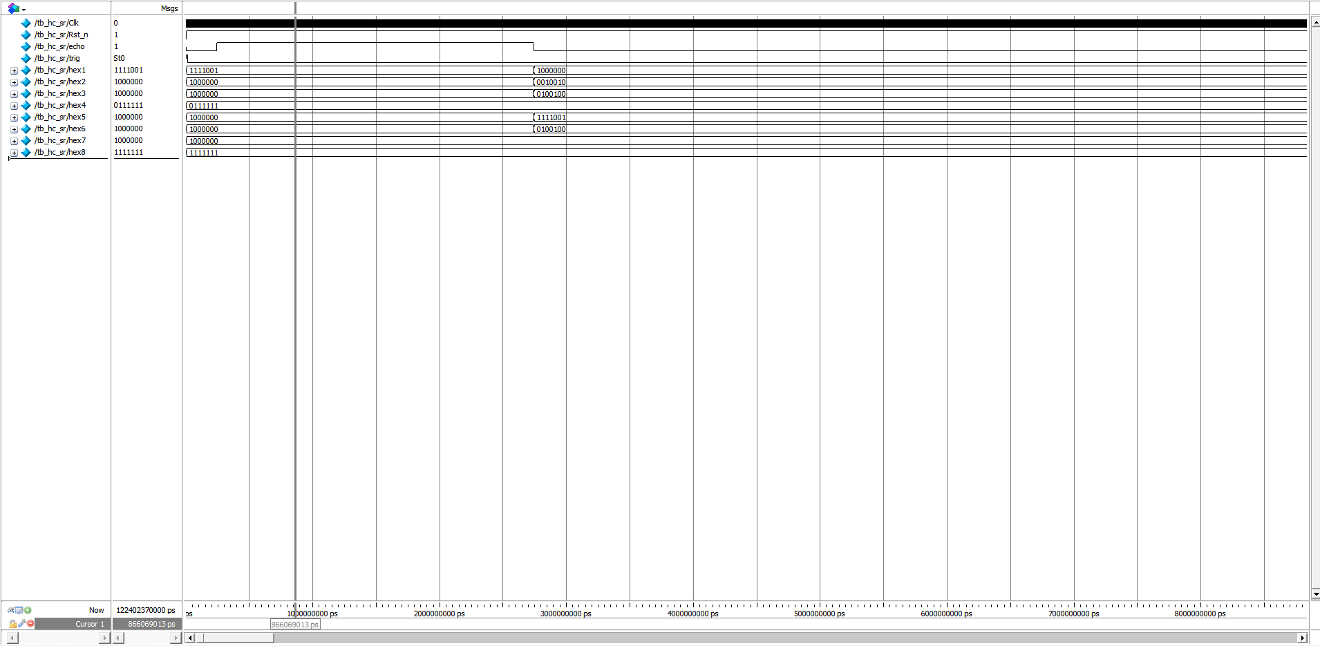
我们对 echo 设计的输入信号对应的距离为 021.250 cm,并设置 trig 输出 10μS 持续高电平,通过输出的位选信号,我们可以看到这就是我们需要的信号,所以可以判断我们的系统已经成功实现了所需要的功能
烧录验证
引脚配置文件如下:
# Copyright (C) 2018  Intel Corporation. All rights reserved.
# Your use of Intel Corporation's design tools, logic functions
# and other software and tools, and its AMPP partner logic
# functions, and any output files from any of the foregoing
# (including device programming or simulation files), and any
# associated documentation or information are expressly subject
# to the terms and conditions of the Intel Program License
# Subscription Agreement, the Intel Quartus Prime License Agreement,
# the Intel FPGA IP License Agreement, or other applicable license
# agreement, including, without limitation, that your use is for
# the sole purpose of programming logic devices manufactured by
# Intel and sold by Intel or its authorized distributors.  Please
# refer to the applicable agreement for further details.

# Quartus Prime Version 18.1.0 Build 625 09/12/2018 SJ Standard Edition
# File: C:\Users\ppqpp\Desktop\FPGA-ultrasonic-ranging-main\HC_SR04\hc_sr04.tcl
# Generated on: Sun May 21 09:32:17 2023

package require ::quartus::project

set_location_assignment PIN_Y2 -to clk
set_location_assignment PIN_M23 -to rstn
set_location_assignment PIN_G18 -to hex1[0]
set_location_assignment PIN_F22 -to hex1[1]
set_location_assignment PIN_E17 -to hex1[2]
set_location_assignment PIN_L26 -to hex1[3]
set_location_assignment PIN_L25 -to hex1[4]
set_location_assignment PIN_J22 -to hex1[5]
set_location_assignment PIN_H22 -to hex1[6]
set_location_assignment PIN_M24 -to hex2[0]
set_location_assignment PIN_Y22 -to hex2[1]
set_location_assignment PIN_W21 -to hex2[2]
set_location_assignment PIN_W22 -to hex2[3]
set_location_assignment PIN_W25 -to hex2[4]
set_location_assignment PIN_U23 -to hex2[5]
set_location_assignment PIN_U24 -to hex2[6]
set_location_assignment PIN_AA25 -to hex3[0]
set_location_assignment PIN_AA26 -to hex3[1]
set_location_assignment PIN_Y25 -to hex3[2]
set_location_assignment PIN_W26 -to hex3[3]
set_location_assignment PIN_Y26 -to hex3[4]
set_location_assignment PIN_W27 -to hex3[5]
set_location_assignment PIN_W28 -to hex3[6]
set_location_assignment PIN_V21 -to hex4[0]
set_location_assignment PIN_U21 -to hex4[1]
set_location_assignment PIN_AB20 -to hex4[2]
set_location_assignment PIN_AA21 -to hex4[3]
set_location_assignment PIN_AD24 -to hex4[4]
set_location_assignment PIN_AF23 -to hex4[5]
set_location_assignment PIN_Y19 -to hex4[6]
set_location_assignment PIN_AB19 -to hex5[0]
set_location_assignment PIN_AA19 -to hex5[1]
set_location_assignment PIN_AG21 -to hex5[2]
set_location_assignment PIN_AH21 -to hex5[3]
set_location_assignment PIN_AE19 -to hex5[4]
set_location_assignment PIN_AF19 -to hex5[5]
set_location_assignment PIN_AE18 -to hex5[6]
set_location_assignment PIN_AD18 -to hex6[0]
set_location_assignment PIN_AC18 -to hex6[1]
set_location_assignment PIN_AB18 -to hex6[2]
set_location_assignment PIN_AH19 -to hex6[3]
set_location_assignment PIN_AG19 -to hex6[4]
set_location_assignment PIN_AF18 -to hex6[5]
set_location_assignment PIN_AH18 -to hex6[6]
set_location_assignment PIN_AA17 -to hex7[0]
set_location_assignment PIN_AB16 -to hex7[1]
set_location_assignment PIN_AA16 -to hex7[2]
set_location_assignment PIN_AB17 -to hex7[3]
set_location_assignment PIN_AB15 -to hex7[4]
set_location_assignment PIN_AA15 -to hex7[5]
set_location_assignment PIN_AC17 -to hex7[6]
set_location_assignment PIN_AD17 -to hex8[0]
set_location_assignment PIN_AE17 -to hex8[1]
set_location_assignment PIN_AG17 -to hex8[2]
set_location_assignment PIN_AH17 -to hex8[3]
set_location_assignment PIN_AF17 -to hex8[4]
set_location_assignment PIN_AG18 -to hex8[5]
set_location_assignment PIN_AA14 -to hex8[6]
set_location_assignment PIN_AB22 -to trig
set_location_assignment PIN_AC15 -to echo

 浙公网安备 33010602011771号