VXLAN Primer
VXLAN Primer-Part 1
http://www.borgcube.com/blogs/2011/11/vxlan-primer-part-1/
There has been a lot of chatter in the bloggersphere about the advent of Virtual eXtensible Local Area Network (VXLAN) and all the vendors that contributed to the standard as well as those that are planning on supporting the proposed IETF draft standard. In the next couple of articles I will attempt to describe how VXLAN is supposed to work as well as give you an idea of when you should consider implementing it, and how to implement it in your VMware Infrastructure (VI).
VXLAN Basics:
The basic use case for VXLAN is to connect two or more layer three (L3) networks and make them look like they share the same layer two (L2) domain. This would allow for virtual machines to live in two disparate networks yet still operate as if they were attached to the same L2. See section 3 of the VXLAN IETF draft as it addresses the networking problems that VXLAN is attempting to solve a lot better than I ever could.
To operate a VXLAN needs a couple of components in place:
- Multicast support, IGMP and PIM
- VXLAN Network Identifier (VNI)
- VXLAN Gateway
- VXLAN Tunnel End Point (VTEP)
- VXLAN Segment/VXLAN Overlay Network
VXLAN is an L2 overlay over an L3 network. Each overlay network is known as a VXLAN Segment and identified by a unique 24-bit segment ID called a VXLAN Network Identifier (VNI). Only virtual machine on the same VNI are allowed to communicate with each other. Virtual machines are identified uniquely by the combination of their MAC addresses and VNI. As such it is possible to have duplicate MAC addresses in different VXLAN Segments without issue, but not in the same VXLAN Segments.

VXLAN Transport Header Format
Figure 1: VXLAN Packet Header
The original L2 packet that the virtual machines send out is encapsulated in a VXLAN header that includes the VNI associated with the VXLAN Segments that the virtual machine belongs to. The resulting packet is then wrapped in a UDP->IP->Ethernet packet for final delivery on the transport network. Due to this encapsulation you can think of VXLAN as a tunneling scheme with the ESX hosts making up the VXLAN Tunnel End Points (VTEP). The VTEPs are responsible for encapsulating the virtual machine traffic in a VXLAN header as well as stripping it off and presenting the destination virtual machine with the original L2 packet.
The encapsulation is comprised of the following modifications from standard UDP, IP and Ethernet frames:
Ethernet Header:
Destination Address – This is set to the MAC address of the destination VTEP if it is local of to that of the next hop device, usually a router, when the destination VTEP is on a different L3 network.
VLAN – This is optional in a VXLAN implementation and will be designated by an ethertype of 0×8100 and have an associated VLAN ID tag.
Ethertype – This is set to 0×0800 as the payload packet is an IPv4 packet. The initial VXLAN draft does not include an IPv6 implementation, but it is planned for the next draft.
IP Header:
Protocol – Set 0×11 to indicate that the frame contains a UDP packet
Source IP – IP address of originating VTEP
Destination IP – IP address of target VTEP. If this is not known, as in the case of a target virtual machine that the VTEP has not targeted before, a discovery process needs to be done by originating VTEP. This is done in a couple of steps:
- Destination IP is replaced with the IP multicast group corresponding to the VNI of the originating virtual machine
- All VTEPs that have subscribed to the IP multicast group receive the frame and decapsulate it learning the mapping of source virtual machine MAC address and host VTEP
- The host VTEP of the destination virtual machine will then send the virtual machines response to the originating VTEP using its destination IP address as it learned this from the original multicast frame
- The Source VTEP adds the new mapping of VTEP to virtual machine MAC address to its tables for future packets
UDP Header:
Source Port – Set by transmitting VTEP
VXLAN Port – IANA assigned VXLAN Port. This has not been assigned yet
UDP Checksum – This should be set to 0×0000. If the checksum is not set to 0×0000 by the source VTEP, then the receiving VTEP should verify the checksum and if not correct, the frame must be dropped and not decapsulated.
VXLAN Header:
VXLAN Flags – Reserved bits set to zero except bit 3, the I bit, which is set to 1 to for a valid VNI
VNI – 24-bit field that is the VXLAN Network Identifier
Reserved – A set of fields, 24 bits and 8 bits, that are reserved and set to zero
Putting it Together:

VXLAN: VM to VM communication
Figure 2: VM to VM communication
When VM1 wants to send a packet to VM2, it needs the MAC address of VM2 this is the process that is followed:
- VM1 sends a ARP packet requesting the MAC address associated with 192.168.0.101
- This ARP is encapsulated by VTEP1 into a multicast packet to the multicast group associated with VNI 864
- All VTEPs see the multicast packet and add the association of VTEP1 and VM1 to its VXLAN tables
- VTEP2 receives the multicast packet decapsulates it, and sends the original broadcast on portgroups associated with VNI 864
- VM2 sees the ARP packet and responds with its MAC address
- VTEP2 encapsulates the response as a unicast IP packet and sends it back to VTEP1 using IP routing
- VTEP1 decapsulates the packet and passes it on to VM1
At this point VM1 knows the MAC address of VM2 and can send directed packets to it as shown in in Figure 2: VM to VM communication:
- VM1 sends the IP packet to VM2 from IP address 192.168.0.100 to 192.168.0.101
- VTEP1 takes the packet and encapsulates it by adding the following headers:
- VXLAN header with VNI=864
- Standard UDP header and sets the UDP checksum to 0×0000, and the destination port being the VXLAN IANA designated port. Cisco N1KV is currently using port ID 8472.
- Standard IP header with the Destination being VTEP2’s IP address and Protocol 0×011 for the UDP packet used for delivery
- Standard MAC header with the MAC address of the next hop. In this case it is the router Interface with MAC address 00:10:11:FE:D8:D2 which will use IP routing to send it to the destination
- VTEP2 receives the packet as it has it’s MAC address as the destination. The packet is decapsulated and found to be a VXLAN packet due to the UDP destination port. At this point the VTEP will look up the associated portgroups for VNI 864 found in the VXLAN header. It will then verify that the target, VM2 in this case, is allowed to receive frames for VNI 864 due to it’s portgroup membership and pass the packet on if the verification passes.
- VM2 receives the packet and deals with it like any other IP packet.
The return path for packet from VM2 to VM1 would follow the same IP route through the router on the way back.
VXLAN Primer-Part 2: Let’s Get Physical
http://www.borgcube.com/blogs/2012/03/vxlan-primer-part-2-lets-get-physical/
Now that the basics are in place with regards to VXLAN and Multicast, we can move on to what needs to be done to get your physical infrastructure ready for VXLAN. The promise of VXLAN is that you do not need to “upgrade” your physical network gear for VXLAN capable gear in order to be up and running, in reality there is very little you need to do. The basic things that need to be addressed are:
- MTU increase
- Multicast support
Let us cover this in a little more detail.
MTU Increase
Looking back to the VXLAN Primer-Part 1 we found that the encapsulation of an IPv4 packet will add an extra 50 bytes to the original frame. The recommendation is to increase the MTU to 1600 bytes. Why 1600 bytes when the VXLAN overhead is only 50 bytes? The reason for this is that the Guest could be doing VLAN tagging, on a max MTU packet of 1514 bytes, adding 4 bytes to the resulting packet. If the transport network requires that the VXLAN traffic be VLAN tagged, this will add another 4 bytes to the final packet. As such:
for IPv4:
1514(Guest) + 4(Guest VLAN tag) + 50(VXLAN) + 4(VXLAN Transport VLAN Tag) = 1572
for IPv6 (IPv6 headers add another 20 bytes):
1514(Guest) + 4(Guest VLAN) + 70(VXLAN IPv6) + 4(VXLAN Transport VLAN Tag) = 1592
IPv6 adds an extra 8 bytes of data and control packets bring this up to 1600 bytes.
The MTU change needs to be made at the vSwitch and on all physical gear that VXLAN traffic will traverse. On the physical gear, this will usually include the TOR switches, Core Switches and routers.
Caution should be taken if one is considering using VXLAN to transport virtual machine traffic that is already configured for jumbo frames and or jumbograms due to the resulting fragmentation.
Multicast Support
Multicast is required by VXLAN in order to transport virtual machine originated traffic such as unknown destination MAC packets, broadcasts, multicast or non IP traffic. It is also used for endpoint discovery by the VTEPs. For details on how multicast works have a look at the previous blog entry on multicast.
There are a couple of ways to get started with multicasting for VXLAN use on the physical network, the simple way and the right way.
The Simple Way
For a simple one-datacenter configuration, you could take the simple route and put all your VTEPs on the same L2 network. This will allow you to run VXLAN without any changes to your network for multicast support. This is also an option to get you started as you prepare to do the right thing as detailed below.
You should be very aware in this configuration, that all multicast traffic will be treated like broadcast traffic by the physical switches. This traffic will be flooded to all ports in the L2 network they are in. This is not a terrible thing in a small VXLAN installation, or if the L2 is dedicated to the VTEPs, as it will get you up and running with no changes on the physical network.
The Right Way
The right way to prepare for VXLAN on the physical network is by enabling multicast support on the switches and routers.
- On the layer 2 switches, you will need to enable IGMP snooping
- On the routers you will need to setup an IGMP queryer
IGMP snooping is needed on the physical switches in order to build a map of the physical ports to multicast addresses in use by the end clients. This allows for multicast pruning on ports that have not subscribed to groups being distributed by the switch. For IGMP snooping to work there has to be at least one IGMP queryer on the network.
An IGMP enabled router sends out IGMP multicast queries to the networks it has configured for multicast. These queries are used to find active multicast groups. The end clients, in the case of VXLAN the VTEPs, will respond with an IGMP Report to join/rejoin or leave an active multicast group that maps to a VXLAN Network Identifier (VNI) associated with a VXLAN segment. The VTEP will respond with the IGMP reply for all the multicast groups that are associated with the various VNIs for the VMs it hosts. These join and leave messages are noted by the switch which modifies it’s multicast tables to match. See this detailed explanation on PIM for a detailed explanation on how this works for multicast clients and sources.
Typical VXLAN Use Case
http://it20.info/2012/05/typical-vxlan-use-case/
One of the problems VXLAN is supposed to solve is the possibility to decouple (and abstract) the compute capacity from the underling network configuration. A lot of people whose background is solely in the compute space now know that there is a solution but don’t really get why there is a problem in the first place.
In this post I’ll attempt to describe the problem first and (in brief) the solution later.
Problem statement
The typical example of this scenario is that a VM needs to be deployed in a specific segment of the network. By that I mean a layer 2 broadcast domain. Free compute capacity should ideally drive the placement of this VM. Instead what happens is that what drives the placement is “where that specific network is available” across the number of clusters deployed. In fact, typically, each cluster has its own set of networks available. So if a specific network “is available” in a cluster that is utilized at 80% that’s where you need to deploy your workload, despite there may be another cluster sitting somewhere else doing pretty much nothing.
Why can’t you make that network available to the idle cluster one may argue? That’s the problem I’d like to double click on now.
When people talk about this they tend to mention “the VLAN is not available in that idle cluster”. I believe talking about VLANs confuses the people that don’t have a good networking background (like myself).
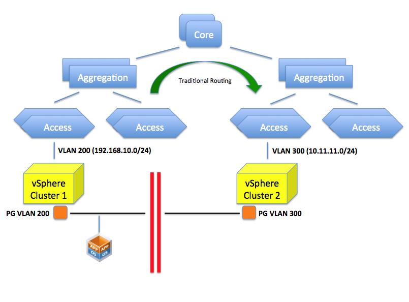
What happens here is that your access layer (TOR switches for example) is configured for one or more VLANs with a specific network. For example VLAN 200 is configured to use a specific network such as 192.168.10.0/24. This VLAN is routed at layer 3 to the other VLANs (or to other networks if you will) available in the infrastructure by means of a router. In a vSphere environment a PortGroup on a vSwitch represents this VLAN and the VLAN 200 (along with potentially others) needs to be made available to a pNIC through a trunk on the Access Layer switch.
In a rack far away there may be another TOR switch serving another vSphere cluster. Let’s assume VLAN 300 is available (along others) on this Access Layer switch and, through a trunk on the pNICs, to the cluster. This VLAN is configured with a 10.11.11.0/24 network segment. As you can imagine, placing a VM in either one of the clusters will determine its network personality. In other words it’s not the same thing.
So can’t you just configure VLAN 200 on this TOR? That is the confusing part. This isn’t so much a VLAN problem but rather a routing problem. You could indeed create a VLAN 200 but which IP network are you going to configure it with? If you assign a 192.168.10.0/24 class that doesn’t mean you have created a single layer 2 domain that spans those two VLANs per se (they are considered two distinct separate broadcast domains). You can possibly configure both of them with the very same IP schema but the end result is that:
- VMs in one network won’t broadcast to the VMs in the other network.
- A VM in one network can’t reach a VM in the other network (given the address of the other VM is considered a local address so the default gateway won’t attempt to route it)
- Every other router/L3 switch will be confused because they won’t know whether to send the packets for 192.168.10.0/24 to the left or right VLAN.
The picture below depicts the limitation mentioned.
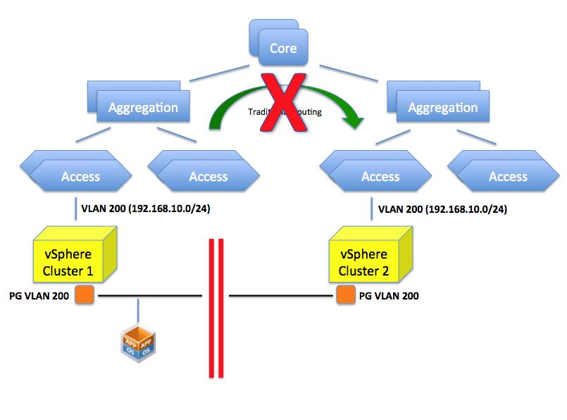
If you assign a 10.11.11.0/24 schema to the VLAN 200 in the second cluster you can certainly route between this and the VLAN 200 on the first cluster (whose class is 192.168.10.0/24) but what would the point be if the objective is to create a flat layer 2 across these two switches and ultimately, across these clusters?
So as you can see it’s not so much about “VLANs not being available”. It’s more about routing and segmentations of VLANs based on the configured IP classes the core of the problem.
Can we create a flat layer 2 network across these elements? Yes we can do this by, for example, creating a GRE tunnel (or EtherIP, L2TPv3 or OTV for that matter) that needs to be configured on the ingress and egress aggregation switches. These protocols, in a nutshell, can extend a layer 2 domain across a layer 3 tunnel.
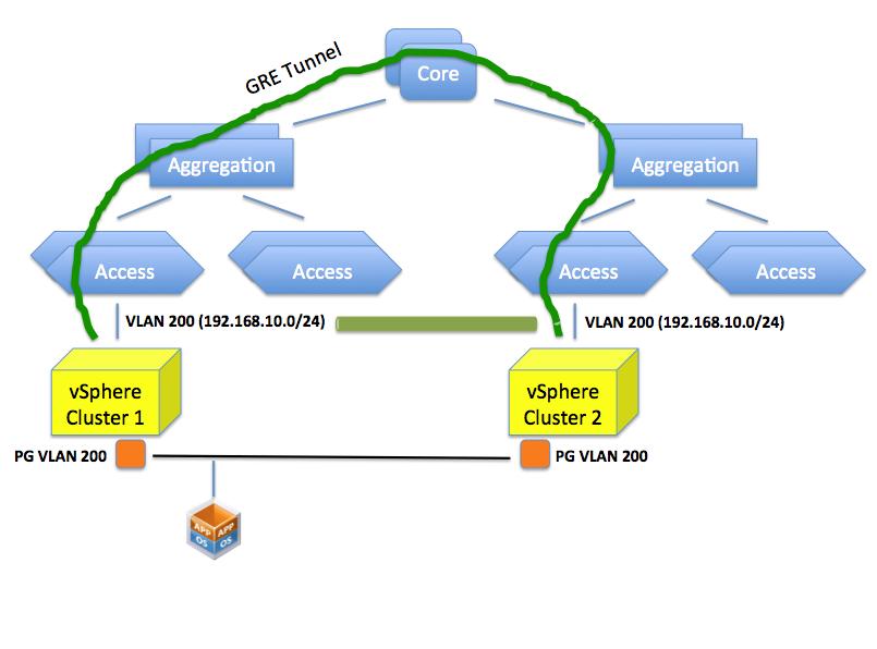
Doing so you are essentially stretching VLAN 200 to the other side of the datacenter. This is different than having two “standalone” VLAN 200’s in different locations of the data center.
This sounds all good but this isn’t usually seen well by network admins because it involves a lot of operational troubles. Consider that in order to create this tunnel all network gears involved in this tunnel (ingress and egress aggregation switches) need to be configured (perhaps manually, perhaps one by one) for this to happen.
The net result is that this doesn’t get done (usually) and the only option is to deploy the VM on the cluster that has visibility of the VLANs that represents the IP network segment the VM needs to end up in.
The Solution
VXLAN provides the solution for the aforementioned problem. By creating an abstraction layer on top of the networking physical infrastructure, the VXLAN technology can bind the two separate layer 2 domains and make them look like one. It essentially presents to the application (or the VM if you will) a contiguous flat layer 2 by connecting (over layer 3) two distinct domains.
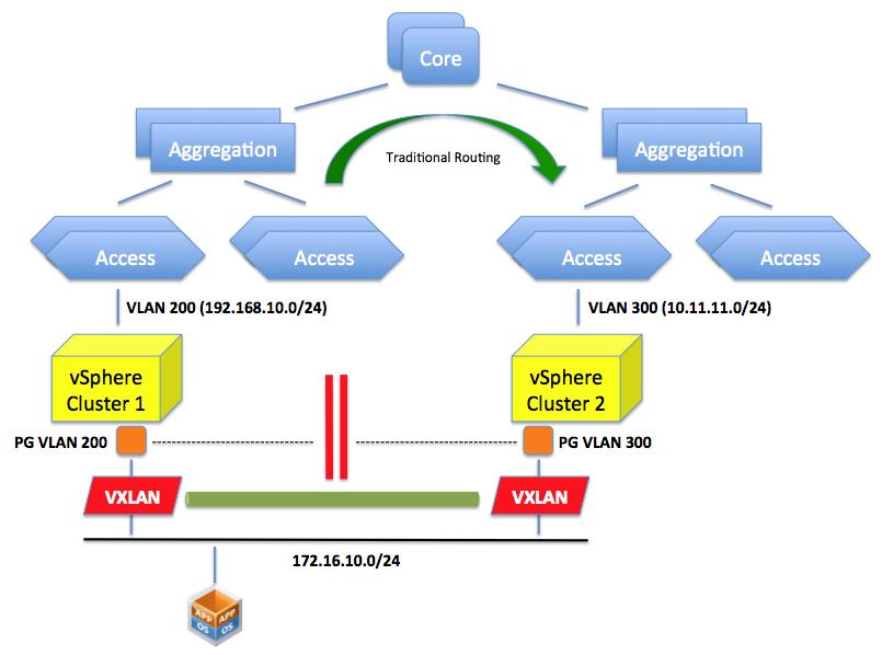
This is not different than what the GRE protocol we described above would do. The difference here is that we do this in the software running on the servers leveraging the standard layer 3 routing in the network.
In other words VXLAN encapsulate the layer 2 traffic and send it over traditional layer 3 connectivity. GRE does a similar thing (conceptually at least) but requires the network to be reconfigured to do this encapsulation. VXLAN does this in an abstraction layer running on the server.
A lot has been already said on the technicality VXLAN uses to achieve this (multicasting) and I appreciate there is space for improvements in how it works. This post is not intended to go deep into the solution, as it was more of a double click on the problem and why we need a “solution”.
Please note what we discussed here is one of the two main use cases for VXLAN: creating a flat layer 2 network across a physical layer 3 network.
There is another use case we haven’t mentioned in this brief article: being able to carve out a number of virtual wires from a single VLAN.
Deja Vu
As I was writing this post my mind sort of went back 10 years and I thought this is exactly the same thing VMware did with server virtualization: a static inflexible server infrastructure that couldn’t be adapted easily to run workloads dynamically. The deployment of a new physical server would have taken weeks.
We resorted to a layer of software that could provide the flexibility on top of a static set of resources that was difficult to provision and reconfigure.
The first wave of change came with ESX where you could take an arbitrarily big server and slice it on the fly to create virtual instances out of that static server. In a way this reminds me what VMware did with the Lab Manager logical networks (and now with VXLAN) in the early days where you could take a VLAN a slice it with a right click of the mouse within the context of an application running on the server.
The second wave came with vMotion and DRS where not only you could apply that abstraction at the single server only but we started to tie together loosely coupled physical resources and make them appear as one to the application. In a way this reminds me what we are doing with VXLAN where we take a static routed network backbone and we create these abstracted and flexible virtual wires to make it appear the way we want.
I understand and appreciate this may not be the most efficient way, from a performance perspective, to consume a network. And I hear lots of networking expert saying that. I don’t argue with that. But wasn’t this the same argument for server virtualization in the early days?
Interesting times ahead. Time will tell.

 浙公网安备 33010602011771号