滑动平均滤波的截止频率与平均点数计算
1. 介绍
滑动平均值滤波可以去除随机噪声。测量中随机噪声的影响,使测量结果不准确,通过多次测量同一数据源,使用多点集合平均的方法得到数据一个比较合理的估计就是滑动平均值滤波。

例如第80采样点的5次平均值滤波:
Y[80] = 1/5( X[80] + X[81] + X[82] + X[83] + X[84] )
这个平均值滤波有时间延迟,最明显的若在正弦采样序列上使用移动平均滤波,则会造成过零点会发生偏移。一般在应用中会加以改进,以当前点为中点,左右各N/2点进行移动平均,遇到N为偶数可以在边界点额外乘以0.5系数。
Y[80] = 1/5( X[78] + X[79] + X[80] + X[81] + X[82] )
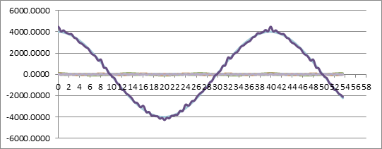
下面是一个简单的实验,在正弦信号上叠加随机噪声,通过移动平均,能够消除测量值上的毛刺。

2. 时域计算方法
平均二字意味着各点的权重相同,如果为各点单独计算权重,则为指数加权滤波。
移动平均计算看似简单,但是却是一个十分耗时的计算,尤其平均点数较多后格外明显。
Y[N] = 1/M * ( X[1]+X[2]+X3[3] + … X[M-1] )
观察计算式,可以发现,每次新测量值相对于上一次的测量值仅2个点不同,丢掉最早的点,累加最新的点,所以能够进行改进。如开头的例子,5点滑动平均滤波。
Y[80] = 1/5( X[78] + X[79] + X[80] + X[81] + X[82] )
改进后,点数越多提升越明显:
Y[80] = Y[79] + 1/5( X[82] - X[77] )
3. 频率特性
移动平均值滤波也是低通滤波器的一种,研究IIR和FIR滤波器的表达式,就可以发现移动平均值滤波是FIR滤波器的一个特例,其每阶的滤波系数都相同。
通用FIR滤波:y[n] = b[0] * x[n] + b[1] * x[n-1] + b[2] * x[n-2] + ...+ b[nums-1] * x[n-nums+1]
令b[0] = b[1] = b[2] =…..= b[nums-1]=1/nums。即 是FIR滤波的特例,可以改写为
 , 其中b[0] = b[1] = b[2] =…..= b[num-1]=1/num。
为了计算简单,直接从连续信号来观察, ,Tw 为平均宽度,该式的频率响应为
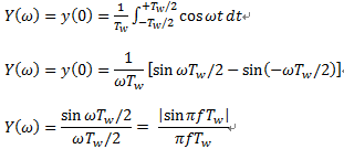
 ,设输入函数x(t) = cos ωt = cos 2πft,当t=0时,x(t)达到最大,X(ω)=x(t=0)=1,Y(ω)=y(t=0)计算如下:

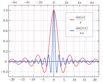
传输函数 , 可见其传输函数是一个sinc函数,频率响应为面积为1的矩形,时域为一个最大值为1的震荡波,当直流信号通过时f=0时,H(f)=1。

截止频率为fco,此时增益为-3db,即衰减倍率为0.707,根据sinc(x)特性曲线,求解sinc(x)=0.707,可得x = 1.3917。 所以sinc(x) = sin(x)/x , 带入H(w)可得  ,化简后:Tw = 0.443/fco.
其中Tw 为平均宽度,采样率已知下,Tw 大小取决于平均点数,Tw = N * T0=N/fs.
那么滑动平均滤波的点数与截止频率之间的关系可以表达为:
N = 0.443* fs /fco .
式中,N为平均的点数,fs为采样频率,fco为截止频率。
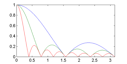
需要注意的是,从上面的sinc(x)特性曲线上可以看出,sinc是一个震荡曲线,所以H(w)会有多个为0的情况。这一点从H(w)的分子也可以得出,当f = n/Tw时,H(w)为0,下图为平均值滤波器在不同截止频率下的频率响应,可以看到图上有多个0点。

4. FFT方法分析滑动滤波的截止频率(参考文献3)
Since the first frequency is almost zero, could I design low pass filter,like Moving Average ?
Fc = (0.443 / Number of Point ) * Fsampling
It is correct?
a moving average filter is this FIR:
{ 1/L 0 <= n < L
h[n] = {
{ 0 otherwise
L is the "number of taps" (if implemented naively) or the length of the
delay (if implemented as a CIC).
it has a definite frequency response, and the -3.01 dB frequency (a.k.a.
"half-power point") can be computed.
H(w) = DTFT{ h[n] }
L-1
= SUM{ 1/L * e^(-j*w*n) }
n=0
L-1
= 1/L * SUM{ e^(-j*w*n) }
n=0
1 - e^(-j*w*L)
= 1/L ---------------
1 - e^(-j*w)
e^(-j*w*L/2) e^(j*w*L/2) - e^(-j*w*L/2)
= 1/L * ------------ * ----------------------------
e^(-j*w/2) e^(j*w/2) - e^(-j*w/2)
= 1/L * e^(-j*w*(L-1)/2) * sin(w*L/2)/sin(w/2)
you can see that in the limit as w->0 H(w) -> 1. now we want to know at what normalized angular frequency w that |H(w)|^2 = 1/2 .
|H(w)|^2 = ( 1/L * sin(w*L/2)/sin(w/2) )^2 = 1/2
now, the icky part is that we have to solve this for the smallest w>0
that |H(w)|^2 = 1/2. and it will be non-simple function of L. if L is
a large integer, then sin(w/2) is about w/2 for any frequency of
interest. then this becomes
sin(w*L/2)/(w*L/2) = sqrt(1/2)
that happens when w*L is about 2.783113 or when w/(2*pi) = 0.442946/L .
this is good only if L >> 1.
5.参考文档
1. Sinc function
https://en.wikipedia.org/wiki/Sinc_function
2. sinc
http://cn.mathworks.com/help/signal/ref/sinc.html
3. Which is the cut -off frequency of Moving Average LP Filter?
https://www.dsprelated.com/showthread/comp.dsp/155807-1.php


【推荐】国内首个AI IDE,深度理解中文开发场景,立即下载体验Trae
【推荐】编程新体验,更懂你的AI,立即体验豆包MarsCode编程助手
【推荐】抖音旗下AI助手豆包,你的智能百科全书,全免费不限次数
【推荐】轻量又高性能的 SSH 工具 IShell:AI 加持,快人一步
· .NET Core 中如何实现缓存的预热?
· 从 HTTP 原因短语缺失研究 HTTP/2 和 HTTP/3 的设计差异
· AI与.NET技术实操系列:向量存储与相似性搜索在 .NET 中的实现
· 基于Microsoft.Extensions.AI核心库实现RAG应用
· Linux系列:如何用heaptrack跟踪.NET程序的非托管内存泄露
· TypeScript + Deepseek 打造卜卦网站:技术与玄学的结合
· Manus的开源复刻OpenManus初探
· .NET Core 中如何实现缓存的预热?
· 三行代码完成国际化适配,妙~啊~
· 阿里巴巴 QwQ-32B真的超越了 DeepSeek R-1吗?