NeHe OpenGL Lesson22 – Bump-Mapping, Multi-Texturing & Extensions
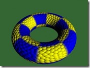
 This sample shows how to do bump mapping with OpenGL. The bump mapping technology used here for approximating diffuse lighting.
The concept behind this article was Embossed bump mapping. The fragment diffuse lighting color C could be evaluated like this:
Cf = (L•N)* Dl * Dm:
L is light direction;
N is vertex normal direction;
DI is light diffuse color;
Dm is material diffuse color; (DI * Dm could be combine into Ct usually)
(L·N) = (Fd + (H1-H0)) , instead of calculating lighting directly with light and normal, we could use some texture maps and other tricks to approximate such diffuse lighting – that is Embossed bump mapping. Fd is the diffuse factor, H1 is the bump map value sample with perturbed coordinates, and H0 is the bump texture value sample with usually coordinates.
The core of the bump mapping is to perturbing bump texture coordinates and do a subtraction between them. For full concept, you could refer to EmbossBumpMapping.ppt included in the downloaded package.
Considering the OpenGL API and hardware multiple texture blending feature support, this sample modify somewhere to make it more easy to implement:
•1) Because Cf = (Fd + (H1-H0)) * Ct
•2) Assume Fd = 1.0, we could get
•3) Cf = (H1+ (1.0-H0)) * Ct
•4) H1 from bump texture and usually coordinates sampling
•5) (1.0 – H0) from inverse previous bump texture, and with perturbed coordinates
•6) GL_ADD H1 and (1.0 – H0)
•7) Add another rendering pass to blend with diffuse color
Because OpenGL texture stage combination result will be clamped into [0, 1]. So only half bump map texture will join the calculation. At the last step, we will store this by scaling with 2.0. To confirm with my thought, I will write a GLSL version to confirm later. The bump map texture usually is a gray scale texture. And the perturbed texture coordinates offsets based on the vertex to light direction, and project this normalized vector along S and T direction in it’s tangent space.
Bumping In & Bumping Out
One thing could be note is that, when you switch the bump texture and inverse texture bounding, you will see bumping effect still there. But the only difference is whether is bumping in or bumping out.
OpenGL Extension on Windows
Windows OS only OpenGL 1.1 supported, because they already had D3D. To access some more advanced features like multiple texture units, texture stage combination, you need to require extensions to GL 1.1. The texture stage combination appeared in GL 1.3, and deprecated in GL 3.0, and fully replace by GLSL in GL 3.1. Texture stage combination was a very useful technology that make you could blend and combine as more effect as possible. Some details document about the texture combination already provided in the downloaded zip file. Document “ogl_texture_gray.pdf” give you more details about how texture mapping going and also a dialog detail the texture stage combination well. Because the max size limitation, so I did not upload this file. You could find it on the web.
Be careful of the glext.h version when you need some extension features. Please make sure the correct version was there.
Another Bumping Sample
 To get more information about the bump mapping technology, another sample also provided here. This sample used Normal map, per pixel diffuse lighting without GLSL. This sample compressed vertex to light direction into cube map, and do GL_DOT3_RGB_ARB between the normal map and cube map without no perturbing texture coordinates.
There was a parallax mapping example under the D3D sample directory. They used perturbed texture coordinates (based on the viewer position and vertex position) for the diffuse map and normal map, diffuse lighting and specular lighting could be calculated per pixel with HLSL. The whole effect is very cool.
The full source code could be downloaded from here.


【推荐】国内首个AI IDE,深度理解中文开发场景,立即下载体验Trae
【推荐】编程新体验,更懂你的AI,立即体验豆包MarsCode编程助手
【推荐】抖音旗下AI助手豆包,你的智能百科全书,全免费不限次数
【推荐】轻量又高性能的 SSH 工具 IShell:AI 加持,快人一步
· 记一次.NET内存居高不下排查解决与启示
· 探究高空视频全景AR技术的实现原理
· 理解Rust引用及其生命周期标识(上)
· 浏览器原生「磁吸」效果!Anchor Positioning 锚点定位神器解析
· 没有源码,如何修改代码逻辑?
· 全程不用写代码,我用AI程序员写了一个飞机大战
· MongoDB 8.0这个新功能碉堡了,比商业数据库还牛
· 记一次.NET内存居高不下排查解决与启示
· DeepSeek 开源周回顾「GitHub 热点速览」
· 白话解读 Dapr 1.15:你的「微服务管家」又秀新绝活了