Electric Power
Power
How Batteries Work
- 电池提供给外面稳定的电压

- 氧化反应,电压会逐渐减少,知道不能给设备供电。
USB
Overview
Types
- Standard connectors
- Mini connectors
- Micro connects
Type A, Type B vs Type C
USB connections are directed, a host device has "downstream" facing ports that connect to the "upstream" facing ports of devices. Only downstream facing ports provide power.
Thus USB cables have different ends: A and B. A(C)<->B(C)
( mostly, A --supply power--> B)

Type C:
- reversible
- bi-directional power capabilities
- better data rates
Data Transfer Rates
Five speeds:
Low Speed, Full Speed, High Speed(version 2.0), SuperSpeed(version 3.0, colored blue), SuperSpeed+(version 3.1)
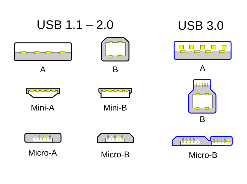
Versions
- USB 1.0: 1.5 Megabits per second at a slow rate -> 12 Mbps(Megabits per second) at full speed.
- USB 2.0: Appearance of Mini TypeA and TypeB
- USB 3.2:20 Gbps(gigabits per second)
- USB4 with USB-C type: 40 Gbps
Terms
- Receptacle, Female, Jack: the connector mounted on the host or device.
- Plug, Male: The connector attached to the cable.
- USB On-The-Go(USB OTG/OTG)
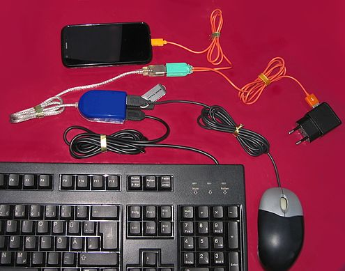
Pinouts
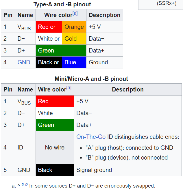
-
USB 2.0 uses two wires for power (VBUS and GND), and two for differential serial data signals. Mini and micro connectors have their GND connections moved from pin #4 to pin #5, while their pin #4 serves as an ID pin for the On-The-Go host/client identification.
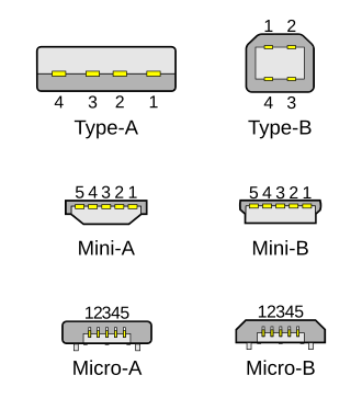
-
USB 3.0 provides two additional differential pairs (four wires, SSTx+, SSTx−, SSRx+ and SSRx−), providing full-duplex data transfers at SuperSpeed, which makes it similar to Serial ATA or single-lane PCI Express.
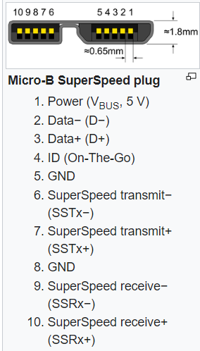
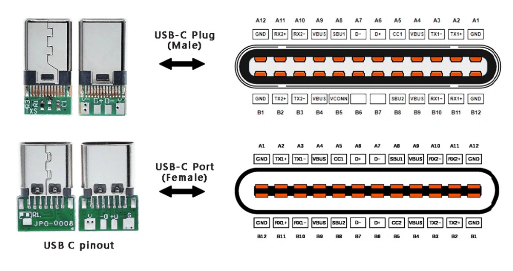
- USB Type C
- CC(Configuration Channel) Line 负责所有PD package的传送。基于BMC(BiPhase Mark Coding)协议在CC线上传输。
- Vbus is the main power line used to supply power to USB devices and typically provides +5V.
- Vconn is a secondary power line used primarily in USB Type-C configurations to power the connector's internal circuitry and manage features, such as orientation detection and improved signal integrity. one of CC line.
debug tools
totalphase Data Center software: https://www.totalphase.com/products/data-center/?srsltid=AfmBOopqhhZx1Z13SjLvO8rEone7XJ7YH_KXOHR34Y4ldOxl_Cpd_Tat
Power
Downstream USB connectors supply power at a nominal 5V DC via the V_Bus pin to upstream USB devices.
Development
- USB的发展 + VBUS(自速电源供电) -> USB 供电的开始
- USB 2.0 + BC (Battery Charging) 规范:提供
5V* 500mA=2.5W的电源功率 - USB 3.0: 提供
5V* 900mA=4.5W - USB 3.0 + BC1.2:
5V*1.5A=7.5W - USB3.0 + Type C + PD技术:
20V*5A=100W - Unlike USB 2.0 and USB 3.2, USB4 does not define its own VBUS-based power model. Power for USB4 operation is established and managed as defined in the USB Type-C Specification and the USB PD Specification.

All devices must act as low-power devices before they are configured.
USB Battery Charging(BC)
- BC defines a charging port, may be a charging downstream port(CDP), with data, or a dedicated charging port(DCP) without data.
- The charging device identifies a charging port by non-data signaling on the D+ and D− terminals. A dedicated charging port places a resistance not exceeding 200 Ω across the D+ and D− terminals
USB-IF BC Spec:
- precise current limits and protocols are established.
- USB data lines(D+/D-)
ref:https://emlogic.no/2023/11/understanding-usb-battery-charging-1-2/
Accessory charging adapters (ACA)
provide portable charging power to an On-The-Go connection between host and peripheral.
USB Power Delivery(USB-PD)
ref:https://www.usbzh.com/article/detail-479.html
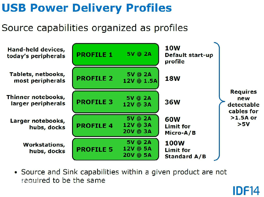
USB PD发展经历了PD1.0,PD2.0,到目前最新的PD3.0。
目前PD各种输出功率的使用场景:
USB PD1.0
是对USB BC的整合,传输功率从7.5W提到100W(20V,5A),
协商
- V_BUS and CC(Channel Configuration)
USB PD快充技术提供了4种电压规格的能力,包含5V/9V/15V/20V。具体使用哪一个,需要进行协商,对于USB2.0,通过V_BUS 来协商,对于USB3.0,通过CC来协商。
Sink(吸端、设备端)和Source(源端,充电端)之间在 CC 线上进行的通讯看起来像如下的样子:
- 设备端申请获得充电端的能力数据。
- 充电端提供它的能力数据信息。
- 设备端从充电端提供的能力数据信息中选出适当的电源配置参数并发出相应的请求。
- 充电端接受请求并将总线电压修改成相应的参数。在总线电压变化期间,设备端的电流消耗会保持尽可能地小(保持高电阻)。充电端提升总线电压的过程是按照定义好的电压提升速度来进行的。总线电压达到最后的数值以后,充电端会等待总线电压稳定下来,再发送出一个电源准备好信号。到了这时候,设备端就可以增加其电流消耗了。
- 当设备端希望总线电压降低的时候,同样的通讯过程也会发生。在总线电压下降期间,充电端会激活一个分流电路,通过主动的总线放电使总线电压快速降低。达到额定值以后,充电端会等待一段稍长的时间让总线电压稳定下来,然后再送出一个电源准备好信号。
NOTE:
- 设备端在总线电压未稳定之前保持较高电阻(即较小电流消耗),当充电端完成电压调整并发出准备好信号后,设备端才可以降低电阻,开始正常充电。
- 这样的通讯方法可确保总线上的任何电源变化都落在源端和吸端的能力范围内,避免出现不可控的状况。当 Type-C电缆的连接被断开时,总线上的电源也被关断,任何新开始的连接都会进行电缆连接检测,电压也总是处于 5V,这 样就可以避免在电缆接通时有高电压从一台设备进入另一台设备 。
VCONN
-
VCONN 是由Pinout中取其中一个CC作为VCONN的,是为了供电给E-Marker来用。
-
E-Marker:是TYPE-C线缆中的一个识别IC(Integrated-Circuit),相当于缆线的身份证,宣告缆线的承载能力、ID及制造商ID
-
在制造缆线时,E-Marker不见得一定是必须的。不过有几个情况下,则一定要放E-Marker IC
1.传输电流需要大于3A
2.需要高速数据传输
电阻 -- 对接
-
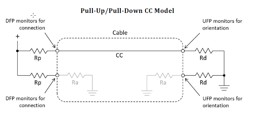
PD规范内,通过定义三个电阻来进行方向性对接的识别。
-
电阻是为了确定Sink端的在5V下的最大电流承载能力的:当Source和Sink连接后,Source端会在CC引脚上输出一个已知电压,并根据CC引脚的电压降来判断下拉电阻的大小。通过这种方式,Source端可以知道Sink端的电流需求能力,或是否连接了E-Marker电缆等。
-
-
Rp:Provider段CC脚位的上拉电阻 10K, 22K, 56K。

-
Pd:Consumer端CC脚位的下拉电阻 5.1K
-
Ra: E-Marker IC 的下拉电阻。
-
SRC_CAP SNK_CAP
通过电阻识别电压完成后,Provider和Consumer已经确定了,Provider在传输角色上设为DFP,Consumer为UFP或Device。然后步骤如下:
-
DFP确认缆线的传输能力,将对缆线的控电权转移到自己身上(默认就在自己这边,如果不在,通过VCONN_swap转换),随后对缆线供电
-
与缆线上的E-Marker IC进行沟通哦,确认缆线的传输能力。
-
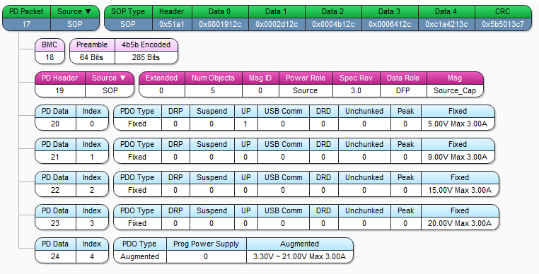
此时Provider会现在VBUS上提供5V电压,CC较为上送出Source Capability(SRC_CAP),SRC_CAP中有Fixed(电压固定),Augmented PDO(PPS)(电压可以在范围内按step变化)
-
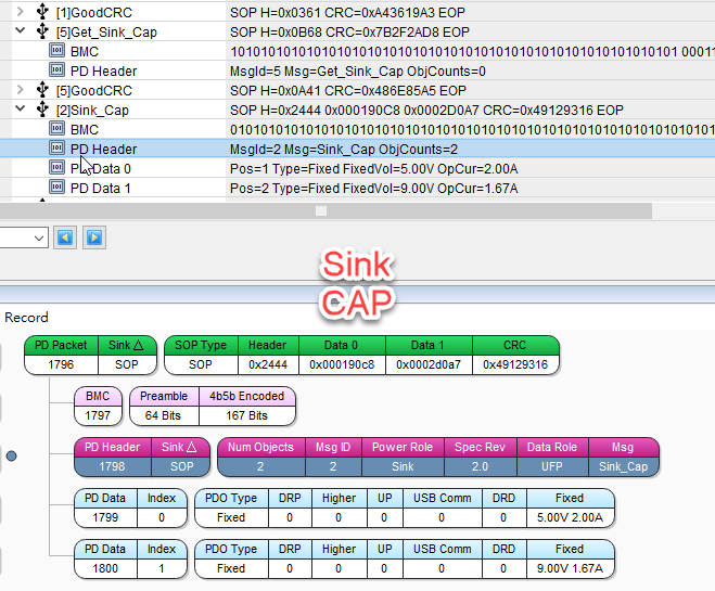
Consumer接收到后,会针对包中的PD Data, 根据Sink Capability(SNK_CAP)挑选一组合适的电压,然后再发需求给Provider。
-
Provider收到需求并产生相对应电压开始供电。
步骤图:

Power Role Swap
当笔记型电脑接入Docking时,会由电脑对Docking供电。如果此时docking有外部电源接入,则docking会发起power role swap的请求,经双方同意后,电源改由docking对笔记型电脑充电,可是data主从关系还是维持由笔记型电脑当Host(DFP ),docking当Device(UFP)。
Mode:
- USB Type-C Default Mode:
- USB 2.0/3.x数据模式: 这是最基础的USB-C模式,适用于没有USB PD功能的设备。VBUS线电力传输,差分数据线数据传输
- USB BC mode
- USB Power Delivery:USB PD是USB-C协议中的一个扩展,允许设备动态协商电力需求,而不仅限于5V的固定电压。
- FRS(Fast Role Swap):FRS是一种特殊的USB PD功能,在系统突然断开电源是,进行快速的电源角色切换。
- Dual-Role Power (DRP) Mode: USB-C设备可以同时支持供电端(Source)和受电端(Sink)模式。设备在连接时可以协商并动态切换角色,这种模式称为Dual-Role Power。
- Dual-Role Data (DRD) Mod: 类似于DRP,Dual-Role Data模式允许设备在数据传输角色上进行交换,设备可以是数据主机(Host)或从机(Device)。
- Alternate Mode: USB-C端口的高级模式,可以传输非USB协议的数据流。如DisplayPort Alternate Mode,HDMI Alternate Mode, Thunderbolt 3/4 Alternate Mode
ref:


