时序分析中的时钟(1)
An essential part of timing analysis is to accurately specify clocks and clock effects, such as latency and uncertainty.
You can specify, report, and analyze clocks as described in the following sections:
• Creating Clocks
• Clock Network Effects
• Multiple Clocks
• Clock Sense
• Pulse Clocks
• Minimum Pulse Width Checks
• Clock-Gating Signal Timing Checks
• Generated Clocks
• Estimated I/O Latency
• Propagated Clocks

Creating Clocks
You must specify all of the clocks in the design by using the create_clock command. This is the command syntax:
create_clock
[source_objects]
[-period period_value]
[-waveform edge_list]
[-name clock_name]
[-add]
The source_object is the place in the design where the clock exists, which is usually an input port but can also be a pin inside the design. The analysis tool traces the clock network so that the clock reaches all registers in the transitive fanout of the source object. If you do not specify a source object, you define a virtual clock, which is a clock used as a reference for setting input delays and output delays but does not physically exist in the design.
Each clock should have its period defined with the -period option. This is the period of time over which the same waveform repeats end-to-end.
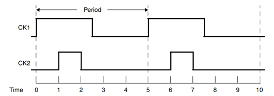
By default, a clock has a 50 percent duty cycle with a rising edge at time zero and a falling edge at one-half the period. If the clock does not have this simple form, you specify the waveform with the -waveform option and provide a list of rising and falling edge times within the clock period. For example, the following commands create a clock having the default waveform and another clock with a rising edge at 1.0 and a falling edge at 2.0. The resulting clock waveforms are shown in Figure 2-1.
prompt> create_clock -period 5.0 [get_ports CK1]
prompt> create_clock -period 5.0 -waveform {1.0 2.0} [get_ports CK2]
Figure 2-1 Clock Waveforms

You can optionally specify a name for the clock with the -name option. If you do not specify a name explicitly, the clock gets its name from the source object. The -add option lets you add multiple clocks to the same source object in the design.
By default, a clock created with the create_clock command is ideal. It has zero delay at the source object, zero propagation delay, zero transition time, and zero uncertainty. For an
accurate timing analysis, you need to specify clock characteristics such as latency, skew, uncertainty, and transition time. To specify the source latency or network latency of the clock,
use the set_clock_latency command. To add skew or uncertainty to an ideal clock, use the set_clock_uncertainty command. To specify the transition time, use the
set_clock_transition command. Alternatively, to enable calculation of propagated delay through the network using wire parasitic data, use the set_propagated_clock command.
To get a report on clocks that have been defined for the design, use the report_clock command. To create a collection of clocks, use the get_clocks or all_clocks command.
For example, to generate a report on the clocks having names starting with PHI1 and a period less than or equal to 5.0, use the following command:
prompt> report_clock [get_clocks -filter "period <= 5.0" PHI1*]
The get_clocks and get_ports commands can be used to distinguish between a clock object and port object that share the same name.
To get a report on the transitive fanout of a clock source, use the report_transitive_fanout command. The report lists the successive driver and load
pins fanning out from the specified source object. Similarly, to get a report on the transitive fanin of a clock sink, use the report_transitive_fanin command. The report shows the
successive driver and load pins in the path feeding into the sink object.
To remove a defined clock, use the remove_clock command. The reset_design command also removes all clocks as well as other design information.

