
11_ADC模数转换器
ADC模数转换器
ADC简介
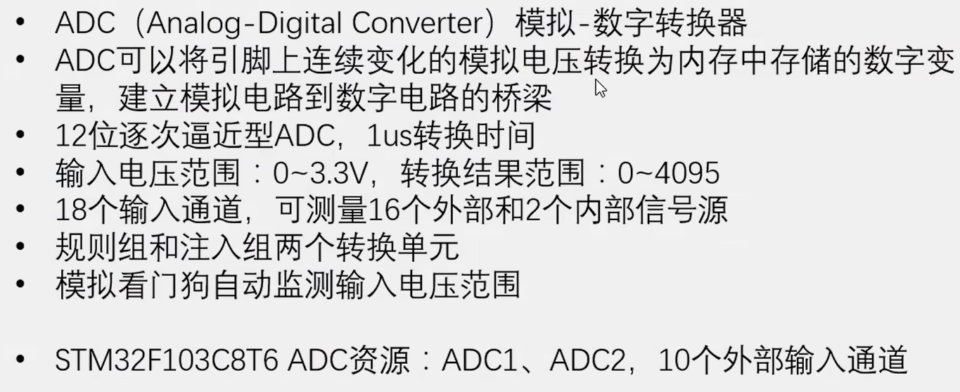
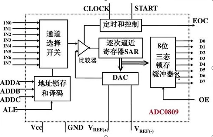
逐次逼近型ADC
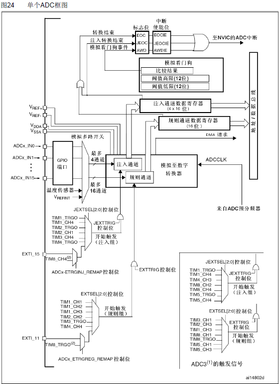
ADC框图
ADC基本结构

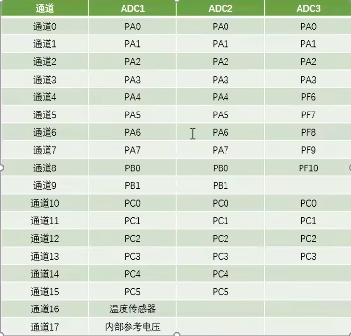
输入通道
转换模式
单次转换,非扫描模式
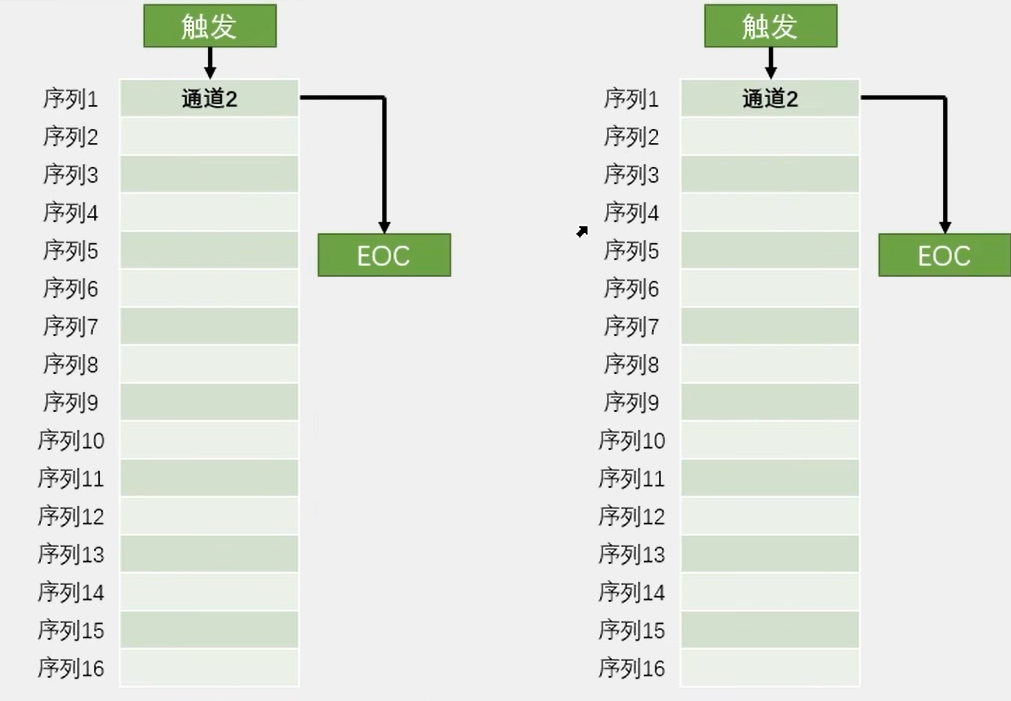
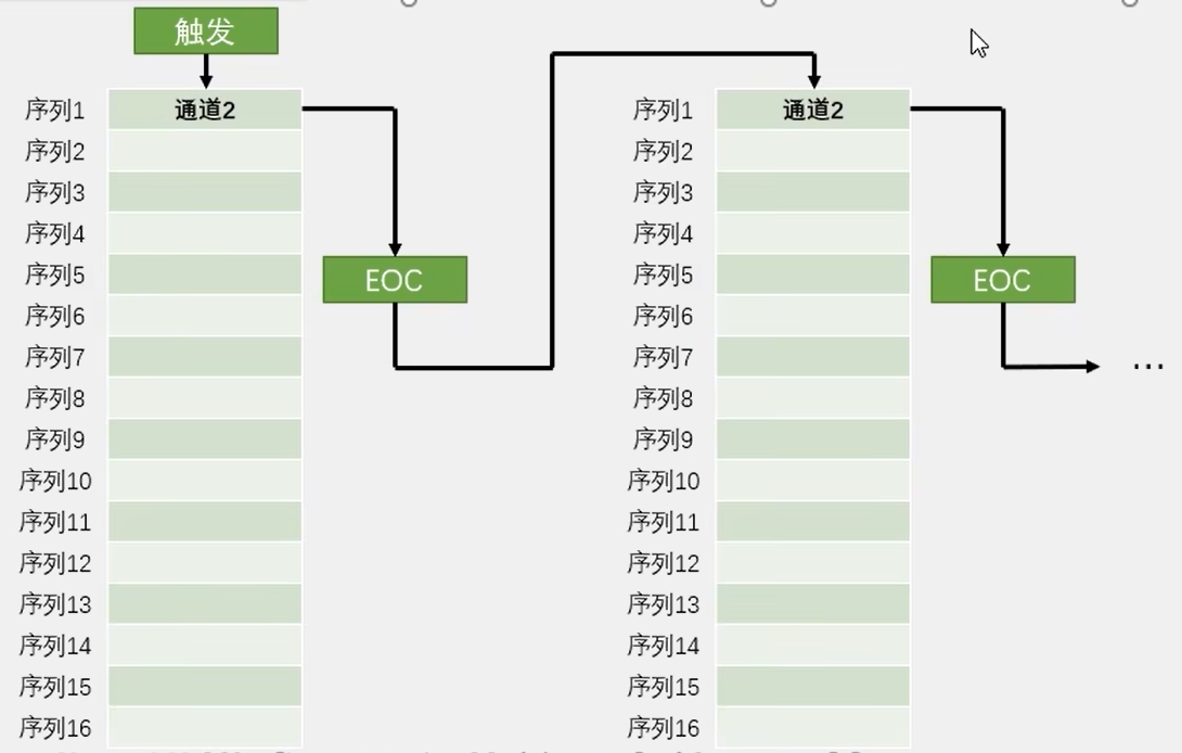
连续转换,非扫描模式
单次转换,扫描模式
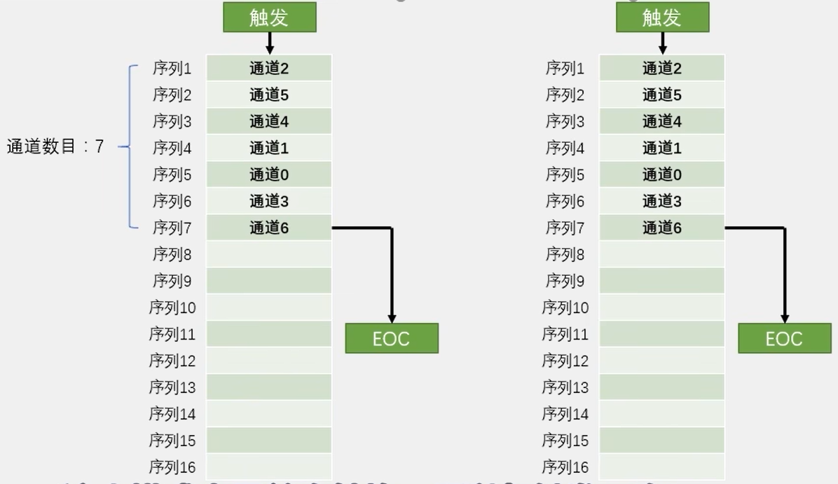
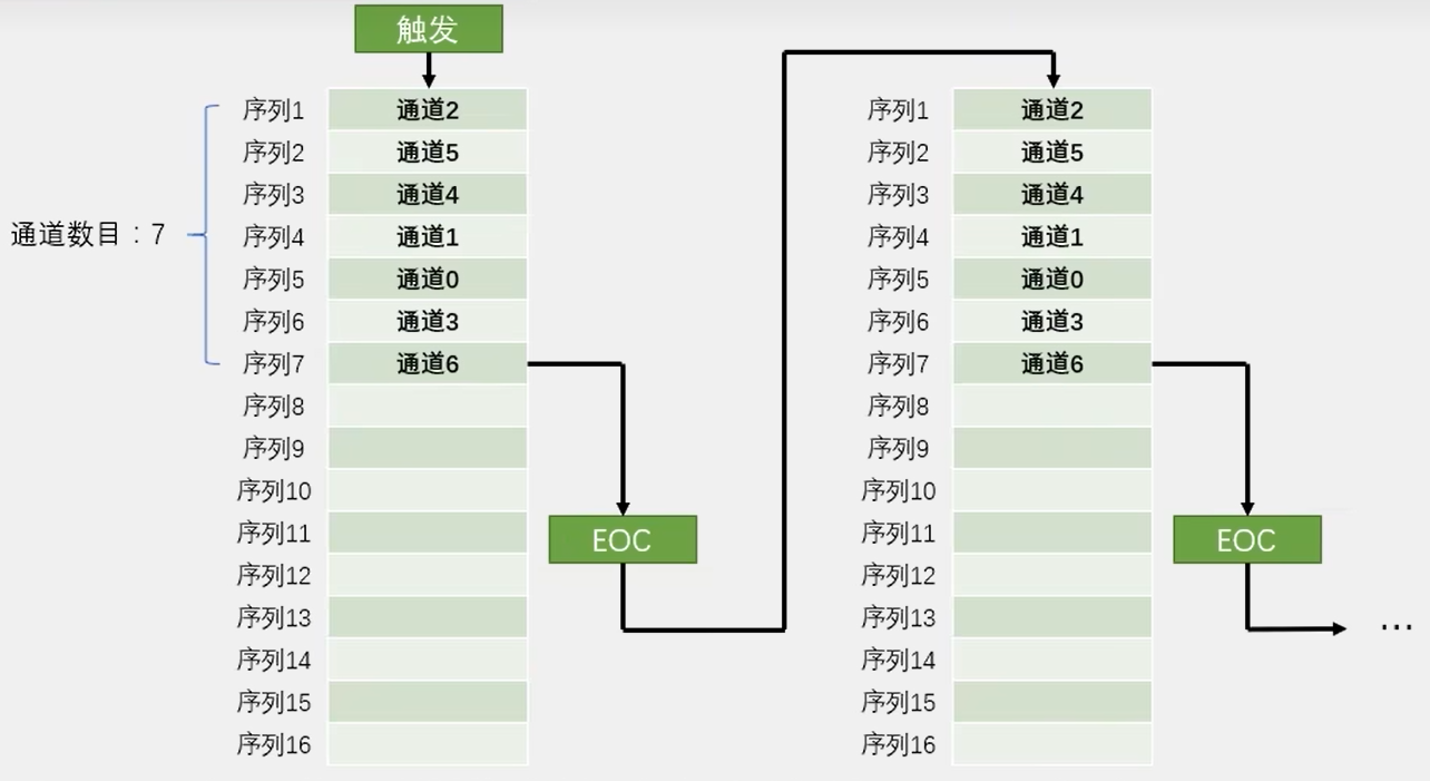
连续转换,扫描模式
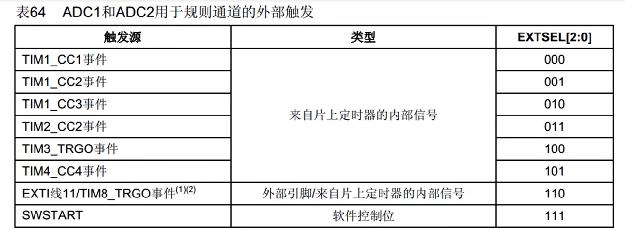
触发控制
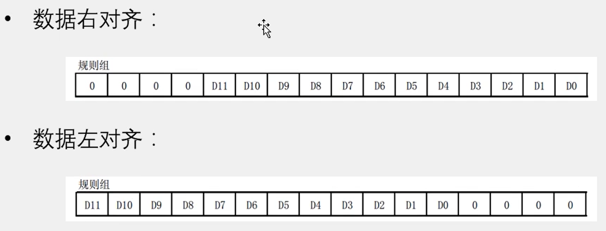
数据对齐
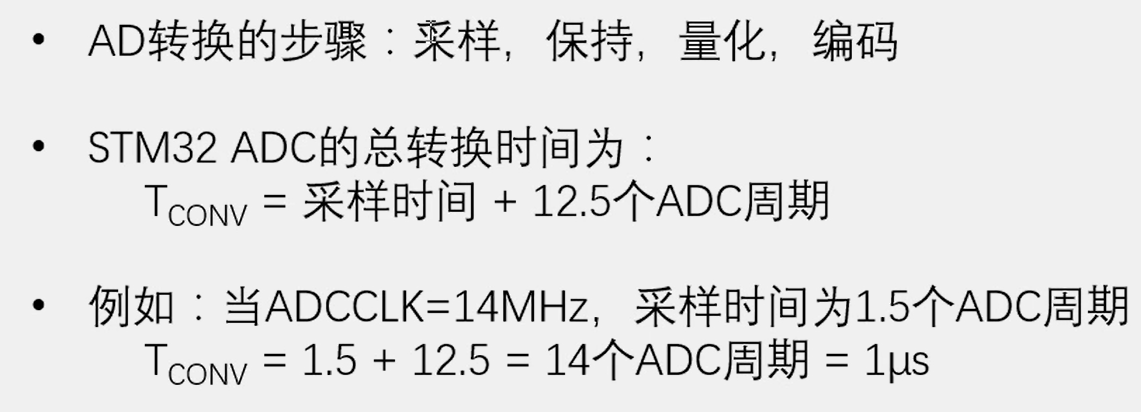
转换时间
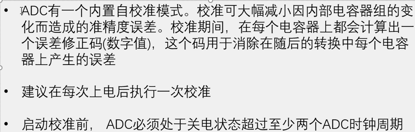
校准
硬件电路
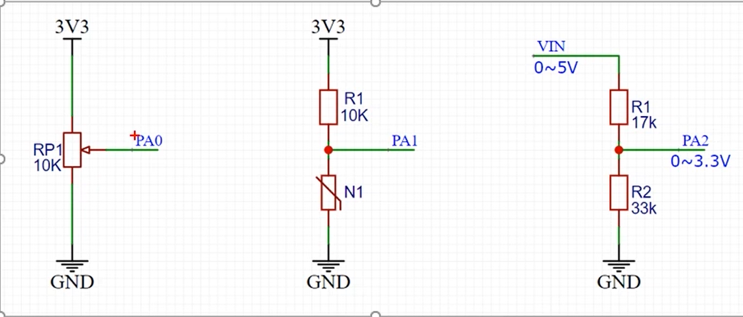
AD单通道
接线图
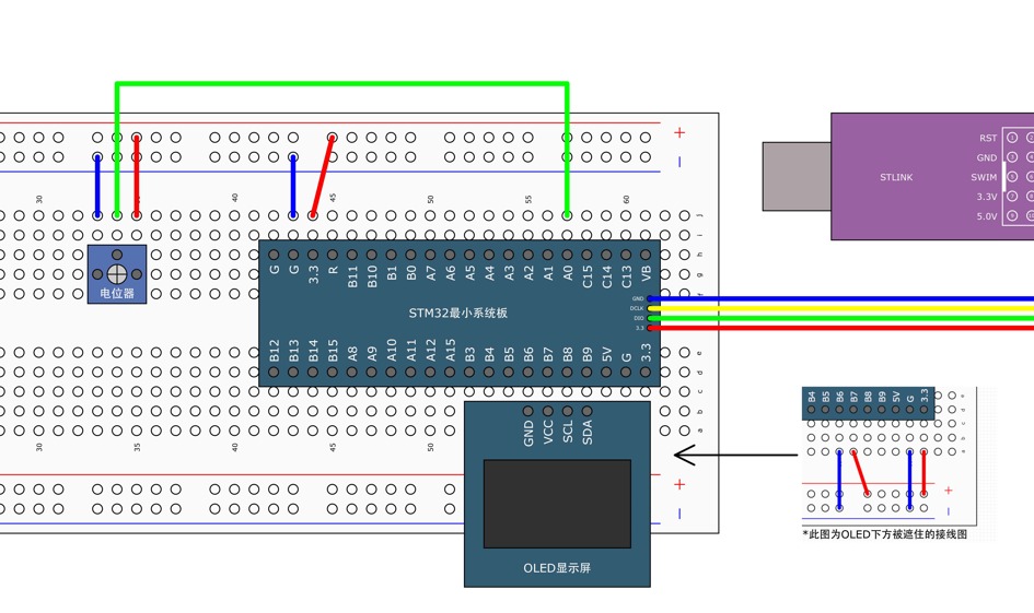
单次转换,非扫描模式
AD.c
#include "stm32f10x.h"                  // Device header

void AD_Init(void)
{
	RCC_APB2PeriphClockCmd(RCC_APB2Periph_GPIOA,ENABLE);
	RCC_APB2PeriphClockCmd(RCC_APB2Periph_ADC1,ENABLE);

	//配置ADCCLK
	RCC_ADCCLKConfig(RCC_PCLK2_Div6); //ADCCLK=72MHz/6=12MHz

	//配置GPIO
	GPIO_InitTypeDef GPIO_InitStruct;
	GPIO_InitStruct.GPIO_Mode=GPIO_Mode_AIN; //模拟输入
	GPIO_InitStruct.GPIO_Pin=GPIO_Pin_0;
	GPIO_InitStruct.GPIO_Speed=GPIO_Speed_50MHz;
	GPIO_Init(GPIOA,&GPIO_InitStruct);

	//选择规则组的输入通道
	ADC_RegularChannelConfig(ADC1,ADC_Channel_0,1,ADC_SampleTime_55Cycles5);

	//初始化ADC
	ADC_InitTypeDef ADC_InitStruct;
	ADC_InitStruct.ADC_ContinuousConvMode=DISABLE; //单次转换
	ADC_InitStruct.ADC_DataAlign=ADC_DataAlign_Right; //数据对齐:右对齐
	ADC_InitStruct.ADC_ExternalTrigConv=ADC_ExternalTrigConv_None; //触发源:软件触发
	ADC_InitStruct.ADC_Mode=ADC_Mode_Independent; //独立模式
	ADC_InitStruct.ADC_NbrOfChannel=1;
	ADC_InitStruct.ADC_ScanConvMode=DISABLE; //非扫描模式
	ADC_Init(ADC1,&ADC_InitStruct);

	//使能ADC
	ADC_Cmd(ADC1,ENABLE);

	//复位校准
	ADC_ResetCalibration(ADC1);
	//等待复位校准完毕
	while(ADC_GetResetCalibrationStatus(ADC1)==SET);
	//开始校准
	ADC_StartCalibration(ADC1);
	//等待校准完成
	while(ADC_GetCalibrationStatus(ADC1)==SET);
}

uint16_t AD_GetValue(void)
{
	//软件触发转换
	ADC_SoftwareStartConvCmd(ADC1,ENABLE);
	//等待转换完成
	while(ADC_GetFlagStatus(ADC1,ADC_FLAG_EOC)==RESET);
	//获取转换结构
	return ADC_GetConversionValue(ADC1);
}
AD.h
#ifndef __AD_H__
#define __AD_H__

void AD_Init(void);
uint16_t AD_GetValue(void);

#endif
main.c
#include "stm32f10x.h"                  // Device header
#include "Delay.h"
#include "OLED.h"
#include "AD.h"

uint16_t ADValue;
float Voltage;

int main(void)
{
	OLED_Init();
	AD_Init();
	OLED_ShowString(1,1,"ADValue:");
	OLED_ShowString(2,1,"Voltage:0.00V");
	while(1)
	{
		ADValue = AD_GetValue();
		Voltage=(float)ADValue/4095*3.3;
		OLED_ShowNum(1,9,ADValue,4);
		OLED_ShowNum(2,9,Voltage,1);
		OLED_ShowNum(2,11,(uint16_t)(Voltage*100)%100,2);
	}
}
连续转换,非扫描模式
AD.c
#include "stm32f10x.h"                  // Device header

void AD_Init(void)
{
	RCC_APB2PeriphClockCmd(RCC_APB2Periph_GPIOA,ENABLE);
	RCC_APB2PeriphClockCmd(RCC_APB2Periph_ADC1,ENABLE);

	//配置ADCCLK
	RCC_ADCCLKConfig(RCC_PCLK2_Div6); //ADCCLK=72MHz/6=12MHz

	//配置GPIO
	GPIO_InitTypeDef GPIO_InitStruct;
	GPIO_InitStruct.GPIO_Mode=GPIO_Mode_AIN; //模拟输入
	GPIO_InitStruct.GPIO_Pin=GPIO_Pin_0;
	GPIO_InitStruct.GPIO_Speed=GPIO_Speed_50MHz;
	GPIO_Init(GPIOA,&GPIO_InitStruct);

	//选择规则组的输入通道
	ADC_RegularChannelConfig(ADC1,ADC_Channel_0,1,ADC_SampleTime_55Cycles5);

	//初始化ADC
	ADC_InitTypeDef ADC_InitStruct;
	ADC_InitStruct.ADC_ContinuousConvMode=ENABLE; //连续转换
	ADC_InitStruct.ADC_DataAlign=ADC_DataAlign_Right; //数据对齐:右对齐
	ADC_InitStruct.ADC_ExternalTrigConv=ADC_ExternalTrigConv_None; //触发源:软件触发
	ADC_InitStruct.ADC_Mode=ADC_Mode_Independent; //独立模式
	ADC_InitStruct.ADC_NbrOfChannel=1;
	ADC_InitStruct.ADC_ScanConvMode=DISABLE; //非扫描模式
	ADC_Init(ADC1,&ADC_InitStruct);

	//使能ADC
	ADC_Cmd(ADC1,ENABLE);

	//复位校准
	ADC_ResetCalibration(ADC1);
	//等待复位校准完毕
	while(ADC_GetResetCalibrationStatus(ADC1)==SET);
	//开始校准
	ADC_StartCalibration(ADC1);
	//等待校准完成
	while(ADC_GetCalibrationStatus(ADC1)==SET);

	//软件触发转换
	ADC_SoftwareStartConvCmd(ADC1,ENABLE);
}

uint16_t AD_GetValue(void)
{
	//获取转换结构
	return ADC_GetConversionValue(ADC1);
}
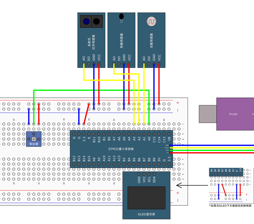
AD多通道
接线图
代码
AD.c
#include "stm32f10x.h"                  // Device header

void AD_Init(void)
{
	RCC_APB2PeriphClockCmd(RCC_APB2Periph_GPIOA,ENABLE);
	RCC_APB2PeriphClockCmd(RCC_APB2Periph_ADC1,ENABLE);

	//配置ADCCLK
	RCC_ADCCLKConfig(RCC_PCLK2_Div6); //ADCCLK=72MHz/6=12MHz

	//配置GPIO
	GPIO_InitTypeDef GPIO_InitStruct;
	GPIO_InitStruct.GPIO_Mode=GPIO_Mode_AIN; //模拟输入
	GPIO_InitStruct.GPIO_Pin=GPIO_Pin_0|GPIO_Pin_1|GPIO_Pin_2|GPIO_Pin_3;
	GPIO_InitStruct.GPIO_Speed=GPIO_Speed_50MHz;
	GPIO_Init(GPIOA,&GPIO_InitStruct);

	//初始化ADC
	ADC_InitTypeDef ADC_InitStruct;
	ADC_InitStruct.ADC_ContinuousConvMode=DISABLE; //单次转换
	ADC_InitStruct.ADC_DataAlign=ADC_DataAlign_Right; //数据对齐:右对齐
	ADC_InitStruct.ADC_ExternalTrigConv=ADC_ExternalTrigConv_None; //触发源:软件触发
	ADC_InitStruct.ADC_Mode=ADC_Mode_Independent; //独立模式
	ADC_InitStruct.ADC_NbrOfChannel=1;
	ADC_InitStruct.ADC_ScanConvMode=DISABLE; //非扫描模式
	ADC_Init(ADC1,&ADC_InitStruct);

	//使能ADC
	ADC_Cmd(ADC1,ENABLE);

	//复位校准
	ADC_ResetCalibration(ADC1);
	//等待复位校准完毕
	while(ADC_GetResetCalibrationStatus(ADC1)==SET);
	//开始校准
	ADC_StartCalibration(ADC1);
	//等待校准完成
	while(ADC_GetCalibrationStatus(ADC1)==SET);
}

uint16_t AD_GetValue(uint8_t ADC_Channel)
{
	//选择规则组的输入通道
	ADC_RegularChannelConfig(ADC1,ADC_Channel,1,ADC_SampleTime_55Cycles5);
	//软件触发转换
	ADC_SoftwareStartConvCmd(ADC1,ENABLE);
	//等待转换完成
	while(ADC_GetFlagStatus(ADC1,ADC_FLAG_EOC)==RESET);
	//获取转换结构
	return ADC_GetConversionValue(ADC1);
}
AD.h
#ifndef __AD_H__
#define __AD_H__

void AD_Init(void);
uint16_t AD_GetValue(uint8_t ADC_Channel);

#endif
main.c
#include "stm32f10x.h"                  // Device header
#include "Delay.h"
#include "OLED.h"
#include "AD.h"

uint16_t AD0,AD1,AD2,AD3;

int main(void)
{
	OLED_Init();
	AD_Init();
	OLED_ShowString(1,1,"AD0:");
	OLED_ShowString(2,1,"AD1:");
	OLED_ShowString(3,1,"AD2:");
	OLED_ShowString(4,1,"AD3:");
	while(1)
	{
		AD0=AD_GetValue(ADC_Channel_0);
		AD1=AD_GetValue(ADC_Channel_1);
		AD2=AD_GetValue(ADC_Channel_2);
		AD3=AD_GetValue(ADC_Channel_3);

		OLED_ShowNum(1,5,AD0,4);
		OLED_ShowNum(2,5,AD1,4);
		OLED_ShowNum(3,5,AD2,4);
		OLED_ShowNum(4,5,AD3,4);

		Delay_ms(100);

	}
}


【推荐】国内首个AI IDE,深度理解中文开发场景,立即下载体验Trae
【推荐】编程新体验,更懂你的AI,立即体验豆包MarsCode编程助手
【推荐】抖音旗下AI助手豆包,你的智能百科全书,全免费不限次数
【推荐】轻量又高性能的 SSH 工具 IShell:AI 加持,快人一步
· 全程不用写代码,我用AI程序员写了一个飞机大战
· DeepSeek 开源周回顾「GitHub 热点速览」
· 记一次.NET内存居高不下排查解决与启示
· 物流快递公司核心技术能力-地址解析分单基础技术分享
· .NET 10首个预览版发布:重大改进与新特性概览!